HP Color LaserJet Enterprise CP5525 Service Manual
HP Color LaserJet Enterprise CP5525 Manual
 |
View all HP Color LaserJet Enterprise CP5525 manuals
Add to My Manuals
Save this manual to your list of manuals |
HP Color LaserJet Enterprise CP5525 manual content summary:
- HP Color LaserJet Enterprise CP5525 | Service Manual - Page 1
HP COLOR LASERJET ENTERPRISE CP5520 PRINTER SERIES Service Manual - HP Color LaserJet Enterprise CP5525 | Service Manual - Page 2
- HP Color LaserJet Enterprise CP5525 | Service Manual - Page 3
HP Color LaserJet Enterprise CP5520 Printer Series Service Manual - HP Color LaserJet Enterprise CP5525 | Service Manual - Page 4
to change without notice. The only warranties for HP products and services are set forth in the express warranty statements accompanying such products and services. Nothing herein should be construed as constituting an additional warranty. HP shall not be liable for technical or editorial errors - HP Color LaserJet Enterprise CP5525 | Service Manual - Page 5
this guide TIP: Tips provide helpful hints or shortcuts. NOTE: Notes provide important information to explain a concept or to complete a task. CAUTION: Cautions indicate procedures that you should follow to avoid losing data or damaging the product. WARNING! Warnings alert you to specific procedures - HP Color LaserJet Enterprise CP5525 | Service Manual - Page 6
iv Conventions used in this guide ENWW - HP Color LaserJet Enterprise CP5525 | Service Manual - Page 7
2 Sequence of operation 3 Normal sequence of operation 3 Formatter-control system ...5 Sleep mode ...5 Input/output ...6 CPU ...6 Memory ...6 Firmware 6 Nonvolatile memory 6 PJL overview ...6 PML ...7 Control panel ...7 Engine-control system ...8 DC controller ...9 Motors ...12 Fans ...14 - HP Color LaserJet Enterprise CP5525 | Service Manual - Page 8
Print cartridges ...35 Memory tag 36 Cartridge presence detection 36 Toner level detection 36 Cartridge life detection 36 Developing unit engagement and detection 40 ITB cleaning mechanism 40 Calibration ...41 Color-misregistration control 42 Environment change control 43 Image stabilization - HP Color LaserJet Enterprise CP5525 | Service Manual - Page 9
approach ...86 Before performing service 86 After performing service 86 Post-service test ...86 Print-quality test 86 Removal and replacement procedures 87 Print cartridges ...87 Toner-collection unit 91 Fuser ...93 Reset the New Fuser Kit setting at the control panel 93 Pickup roller (Tray - HP Color LaserJet Enterprise CP5525 | Service Manual - Page 10
assembly 113 Left cover 115 Rear cover 116 Remove the rear cover 116 Toner collection unit access door 117 Right-rear cover 119 Reinstall the right-rear 145 ITB front guide assembly 148 ITB rear guide assembly 151 Residual toner full sensor 152 Remove the residual toner full sensor 152 - HP Color LaserJet Enterprise CP5525 | Service Manual - Page 11
models 187 Remove the duplex-drive assembly 187 Delivery drive assembly (simplex models 189 Remove the delivery drive assembly 189 Residual-toner-feed assembly 190 Remove the residual-toner-feed assembly 190 ITB motor (M1 192 Remove the ITB motor 192 Drum motor (M2 194 Remove the drum motor - HP Color LaserJet Enterprise CP5525 | Service Manual - Page 12
assembly 230 1 x 500 lifter-drive assembly 233 1 x 500 pickup motor 234 1 x 500 driver PCA 235 3 x 500-sheet paper feeder (optional accessory 236 3 x 500 rear cover 236 3 assembly 251 3 Solve problems ...253 Solve problems checklist ...254 Menu map ...256 Current settings pages 256 x ENWW - HP Color LaserJet Enterprise CP5525 | Service Manual - Page 13
menu 276 Backup/Restore menu 276 Calibration/Cleaning menu 277 USB Firmware Upgrade menu 277 Service menu 278 Troubleshooting process ...279 Determine the problem source 279 Pre-troubleshooting checklist 279 Troubleshooting flowchart 280 Power subsystem 282 Power-on checks 282 Power-on - HP Color LaserJet Enterprise CP5525 | Service Manual - Page 14
Fuser pressure-release sensor (PS9 296 Fuser output sensor (PS6 297 Developer alienation sensor (PS11 298 ITB alienation switch (SW5 299 Tray/Bin manual sensor test 300 Tray 1 paper sensor (PS2 302 Tray 2 paper present sensor (PS1 303 Tray 2 paper surface sensor (PS4 304 Tray 2 paper size - HP Color LaserJet Enterprise CP5525 | Service Manual - Page 15
HP embedded Jetdirect page 352 Finding important information on the configuration pages 353 Color-band test 354 Print quality troubleshooting 391 Troubleshooting menu 401 Device Maintenance menu 406 Backup/Restore menu 406 Calibration/Cleaning menu 407 USB Firmware Upgrade menu 408 Service - HP Color LaserJet Enterprise CP5525 | Service Manual - Page 16
low 413 10.XX.34 Used supply in use 414 10.XX.40 Genuine HP supplies installed 414 10.XX.41 Unsupported supply in use 415 10.XX.70 Printing very low 415 10.YY.15 Install - HP Color LaserJet Enterprise CP5525 | Service Manual - Page 17
437 47.04.XX 437 47.05.00 437 47.06.XX 437 47.WX.YZ Printer calibration error To continue, press OK 437 50.WX.YZ Fuser error To continue, on 452 80.0X.YY Embedded JetDirect error 452 98.00.01 Corrupt data in firmware volume 454 98.00.02 Corrupt data in solutions volume 454 98.00.03 Corrupt - HP Color LaserJet Enterprise CP5525 | Service Manual - Page 18
460 99.09.65 Disk data error 460 99.09.66 No disk data installed 460 99.09.67 Disk is not bootable please download firmware 460 99.XX.YY 461 Full Remove all paper from bin 461 almost full 461 low OR Supplies low 461 very - HP Color LaserJet Enterprise CP5525 | Service Manual - Page 19
is empty 470 Expected drive missing 470 HP Secure Hard Drive disabled 470 Incompatible - HP Color LaserJet Enterprise CP5525 | Service Manual - Page 20
484 Restricted from printing in color 485 Rotating motor 485 Rotating motor 485 Size mismatch in Tray - HP Color LaserJet Enterprise CP5525 | Service Manual - Page 21
or will not feed in the product 519 Output is curled or wrinkled 519 Product will not duplex or duplexes incorrectly 520 Use manual print modes ...521 Solve image-quality problems 524 Print quality examples 524 Clean the product ...531 Clean the paper path 531 Set up an auto cleaning page 531 - HP Color LaserJet Enterprise CP5525 | Service Manual - Page 22
547 Perform a firmware upgrade 547 Embedded Web Server 547 USB storage device (Preboot menu 548 USB storage device (control-panel menu 549 4 Parts and diagrams ...551 Order parts by authorized service providers 552 Order parts, accessories, and supplies 552 Related documentation and software - HP Color LaserJet Enterprise CP5525 | Service Manual - Page 23
statement 633 Color LaserJet Fuser Kit, Transfer Kit, and Toner Collection Unit Limited Warranty Statement .......... 634 Data stored on the print cartridge 635 End User License Agreement 636 Customer self-repair warranty service 638 Customer support ...639 Appendix B Product specifications 641 - HP Color LaserJet Enterprise CP5525 | Service Manual - Page 24
651 Hard-disk-drive memory 651 Safety statements ...652 Laser safety ...652 Canadian DOC regulations 652 VCCI statement (Japan 652 Power cord instructions 652 Power cord statement (Japan 652 EMC statement (China 653 EMC statement (Korea 653 EMI statement (Taiwan 653 Laser statement for - HP Color LaserJet Enterprise CP5525 | Service Manual - Page 25
1 Theory of operation ● Basic operation ● Formatter-control system ● Engine-control system ● Image-formation system ● Pickup, feed, and delivery system ● Paper feeder ● Optional 3X500-sheet paper deck ENWW 1 - HP Color LaserJet Enterprise CP5525 | Service Manual - Page 26
Basic operation Major product systems The product contains the following five systems: ● Engine-control system ● Laser scanner system ● Image-formation system ● Media feed system ● Optional paper feeder system Product block diagram Figure 1-1 Product block diagram LASER SCANNER SYSTEM ENGINE - HP Color LaserJet Enterprise CP5525 | Service Manual - Page 27
the print cartridge and any cartridge changes ● Detects the ITB, and moves the ITB and the developing unit to the home position ● Cleans residual toner from the intermediate transfer belt (ITB) and the secondary transfer roller STBY (standby) From the end of the WAIT or LSTR period until either - HP Color LaserJet Enterprise CP5525 | Service Manual - Page 28
end of the PRINT period until the main motor stops rotating. Purpose Prints ● Forms the image on the photosensitive drum ● Transfers the toner image to the paper ● Fuses the toner image to the paper Moves the last printed sheet to the output bin. ● Stops the high-voltage power supply ● Stops the - HP Color LaserJet Enterprise CP5525 | Service Manual - Page 29
bidirectional interface The formatter receives a print job from the network or bidirectional interface and separates it into image information and instructions that control the printing process. The DC controller PCA synchronizes the image-formation system with the paper-input and -output systems - HP Color LaserJet Enterprise CP5525 | Service Manual - Page 30
product encounters a problem when managing available memory, a clearable warning message appears on the control-panel display. Firmware The firmware is contained PJL overview The printer job language (PJL) is an integral part of configuration, in addition to the standard printer command language ( - HP Color LaserJet Enterprise CP5525 | Service Manual - Page 31
the product in landscape mode, the subsequent print jobs print in landscape mode only if they are formatted for landscape printing. PML The printer management language (PML) allows remote configuration and status read-back through the I/O ports. Control panel The formatter sends and receives product - HP Color LaserJet Enterprise CP5525 | Service Manual - Page 32
Engine-control system The engine-control system coordinates all product functions, according to commands that the formatter sends. The engine-control system drives the laser/scanner system, the image formation system, and the pickup/feed/delivery system. The engine control system contains the - HP Color LaserJet Enterprise CP5525 | Service Manual - Page 33
DC controller The DC controller controls the operational sequence of the product. Figure 1-3 DC controller diagram Cartridge (x4) Developing highvoltage power supply ITB ass'y Transfer 1 highvoltage power supply T2 roller Transfer 2 highvoltage power supply Fuser DC controller AC input Fan - HP Color LaserJet Enterprise CP5525 | Service Manual - Page 34
switch 5V interlock switch 1 5V interlock switch 2 Primary transfer disengagement switch Toner collection unit switch Tray 2 cassette media end guide position switch Tray 2 cassette media width guide position switch Tray 2 cassette pickup solenoid Tray 1 pickup solenoid Duplex reverse solenoid - HP Color LaserJet Enterprise CP5525 | Service Manual - Page 35
Table 1-2 Electrical components (continued) Component type Abbreviation Motor M1 M2 M3 M4 M5 M6 M7 M8 M9 Tray 2 cassette lifter motor M10 Scanner motor Name ITB Motor Drum motor Developing motor Fuser motor Pickup motor Developing disengagement motor Duplex reverse motor (duplex - HP Color LaserJet Enterprise CP5525 | Service Manual - Page 36
Motors The product has ten motors for paper feed and image formation. The DC controller determines there is a motor failure if a motor does not reach a specified speed within a specified period after motor startup, or if the rotational speed is outside a specified range for a specified period.` - HP Color LaserJet Enterprise CP5525 | Service Manual - Page 37
Table 1-3 Motors Description Components driven ITB motor (M1) ITB Black photosensitive drum Black developing roller Drum motor (M2) Yellow, magenta, and cyan photosensitive drums Developing motor (M3) Yellow, magenta, and cyan developing rollers Fuser motor (M4) Fuser pressure and delivery - HP Color LaserJet Enterprise CP5525 | Service Manual - Page 38
Fans The product uses three fans to maintain the correct internal temperature. The DC controller determines a fan failure when a fan locks for a specified period after it starts driving. Figure 1-5 Fans Power supply fan Table 1-4 Fans Description Power supply fan (FM1) Fuser (FM2) Formatter (FM3) - HP Color LaserJet Enterprise CP5525 | Service Manual - Page 39
Fuser-control circuit The fuser-control circuit monitors and controls the temperature in the fuser. The product uses on-demand fusing. The fuser-control circuit consists of the following major components: ● Fuser main heater (H1): Heats the center of the fuser sleeve ● Fuser sub heater (H2): - HP Color LaserJet Enterprise CP5525 | Service Manual - Page 40
Fuser temperature control The fuser temperature control maintains the fuser heater at its targeted temperature. The fuser main heater and sub heater control the temperature of the fuser sleeve. The DC controller monitors the main thermistor and the sleeve thermistor. The DC controller controls the - HP Color LaserJet Enterprise CP5525 | Service Manual - Page 41
Fuser protective function The protective function detects an abnormal temperature rise of the fuser unit and interrupts power supply to the fuser heater. The following three protective components prevent an abnormal temperature rise of the fuser heater: ● DC controller ◦ The DC controller interrupts - HP Color LaserJet Enterprise CP5525 | Service Manual - Page 42
Fuser failure detection The DC controller determines a fuser unit failure, deactivates the FUSER HEATER CONTROL signal, releases the relay to interrupt power supply to the fuser heater, and then notifies the formatter of a failure state when it encounters the following conditions: ● Abnormal - HP Color LaserJet Enterprise CP5525 | Service Manual - Page 43
Low-voltage power supply The low-voltage power supply (LVPS) converts AC input voltage to DC voltage. Figure 1-8 Low-voltage power supply Low-voltage power supply Power switch SW1 Formatter FU101 Noise filter Rectifying circuit +3.3V generation circuit Remote switch control circuit +3.3V - HP Color LaserJet Enterprise CP5525 | Service Manual - Page 44
+5V +5R +3.3V Supplied constantly Stopped during Sleep mode Interrupted when the front or right door is opened Supplied constantly 20 Chapter 1 Theory of operation ENWW - HP Color LaserJet Enterprise CP5525 | Service Manual - Page 45
the power cord is plugged into a power receptacle and the power switch is in the off position. You must unplug the product power cord before servicing the product. WARNING! If you believe the overcurrent or overvoltage protection circuits have been activated, do not plug in the product power cord or - HP Color LaserJet Enterprise CP5525 | Service Manual - Page 46
surface of the photosensitive drum to charge it uniformly negative as a preparation for the image formation. ● Developing roller: The developing bias is used to adhere toner to an electrostatic latent image formed on the photosensitive drum. 22 Chapter 1 Theory of operation ENWW - HP Color LaserJet Enterprise CP5525 | Service Manual - Page 47
● Primary transfer roller: The primary transfer bias is used to transfer the toner from each photosensitive drum onto the ITB. ● Secondary transfer roller: The secondary transfer bias is used to transfer the toner image from the ITB onto the paper. The reversed bias is applied to transfer residual - HP Color LaserJet Enterprise CP5525 | Service Manual - Page 48
Laser scanner system The laser scanner system forms latent images on the photosensitive drums according to the VIDEO signals sent from the formatter. The main components of the laser/scanner are the laser unit and the scanner motor unit. The DC controller sends signals to the laser/scanner to - HP Color LaserJet Enterprise CP5525 | Service Manual - Page 49
Laser failure detection The DC controller determines an optical unit failure and notifies the formatter, if the laser/scanner encounters the following conditions: ● The scanner motor does not reach a specified rotation frequency within a specified period of the scanner motor start up. ● The beam - HP Color LaserJet Enterprise CP5525 | Service Manual - Page 50
● Intermediate transfer belt (ITB) ● Secondary transfer roller ● Fuser ● Laser scanner The DC controller uses the laser scanner and HVPS to form the toner image on the photosensitive drum. The image is transferred to the print media and then fused onto the paper. Figure 1-11 Electrophotographic - HP Color LaserJet Enterprise CP5525 | Service Manual - Page 51
Figure 1-12 Electrophotographic process drive system M2 Drum motor M4 Fuser motor Developing roller Developing roller Developing roller Developing roller M3 Developing motor M1 ITB motor ENWW Image-formation system 27 - HP Color LaserJet Enterprise CP5525 | Service Manual - Page 52
Image formation process Each of the following processes functions independently and must be coordinated with the other product processes. Image formation consists of the following processes: Latent-image formation block Step 1: pre-exposure Step 2: primary charging Step 3: laser-beam exposure - HP Color LaserJet Enterprise CP5525 | Service Manual - Page 53
Latent-image formation block During the latent-image formation stage, the laser scanner forms invisible images on the photosensitive drums in the print cartridges. Pre-exposure Step 1: Light from the pre-exposure LED strikes the photosensitive drum surface. This eliminates the residual electrical - HP Color LaserJet Enterprise CP5525 | Service Manual - Page 54
Laser beam exposure Step 3: The laser beam scans the photosensitive drum to neutralize negative charges on parts of the drum surface. An electrostatic latent image is formed on the drum where negative charges were neutralized. Figure 1-16 Laser beam exposure Laser beam 30 Chapter 1 Theory of - HP Color LaserJet Enterprise CP5525 | Service Manual - Page 55
blade. The developing bias is applied to the developing roller to create a difference in the electric potential of the drum. When the negatively charged toner comes in contact with the photosensitive drum, it adheres to the latent image because the drum surface has a higher potential. Figure 1-17 - HP Color LaserJet Enterprise CP5525 | Service Manual - Page 56
(ITB). The ITB is given a positive charge by the bias of the primary transfer roller. The negatively charged toner on the drum surface is transferred onto the ITB. All four color planes are transferred onto the ITB in this step. Figure 1-18 Primary transfer Primary transfer bias Primary transfer - HP Color LaserJet Enterprise CP5525 | Service Manual - Page 57
20 Separation Secondary transfer opposed roller ITB Static charge eliminator Paper Secondary transfer roller Fusing block Step 8: The product uses an on-demand fuser. The toner image is permanently affixed to the printing paper by heat and pressure. Figure 1-21 Fusing Fuser sleeve Fuser heater - HP Color LaserJet Enterprise CP5525 | Service Manual - Page 58
ITB cleaning block Step 9: The cleaning blade scrapes the residual toner off the surface of the ITB. The residual toner feed screw deposits residual toner in the toner collection unit. Figure 1-22 ITB cleaning Residual toner feed screw ITB Cleaning blade Drum cleaning block Step 10: The cleaning - HP Color LaserJet Enterprise CP5525 | Service Manual - Page 59
Print cartridges The product has four print cartridges, one for each color: yellow, magenta, cyan, and black. Each of them has the same structure. The cartridges are filled with toner and consist of the following components: ● Photosensitive drum ● Developing unit ● Primary charging roller The DC - HP Color LaserJet Enterprise CP5525 | Service Manual - Page 60
a specified amount or the cartridge runs out of toner. Developing unit engagement and disengagement control The developing unit developing units disengage from the photosensitive drums. When the print mode is in full-color mode, all of the developing units engage with the drums. When the print mode - HP Color LaserJet Enterprise CP5525 | Service Manual - Page 61
The DC controller determines a developing disengagement motor abnormality and notifies the formatter when it does not detect a specified signal from the developing disengagement sensor during the developing roller engagement and disengagement operation. Figure 1-25 Developing unit engagement and - HP Color LaserJet Enterprise CP5525 | Service Manual - Page 62
image from the photosensitive drums and transfers the complete toner image to the print media. The ITB unit consists of the following components: ● ITB ● ITB drive roller ● Primary transfer rollers ● ITB cleaner The ITB motor - HP Color LaserJet Enterprise CP5525 | Service Manual - Page 63
control Figure 1-27 Primary transfer roller engagement and disengagement control DC controller M4 Fuser motor Primary transfer disengagement solenoid SL5 ITB SW5 Primary transfer disengagement switch Primary transfer disengagement cam YMC slide plate - HP Color LaserJet Enterprise CP5525 | Service Manual - Page 64
four photosensitive drums. This is the state for full-color jobs. ● Only black roller engaged: The ITB toner feed screw and the screw deposits the residual toner in the toner collection unit. The DC controller detects whether the toner collection unit is full by monitoring the ITB residual toner - HP Color LaserJet Enterprise CP5525 | Service Manual - Page 65
sensor ITB Cleaning blade ITB cleaner Residual toner feed screw Toner collection unit M1 ITB motor Calibration The product calibrates itself to print a high-quality image. The calibration corrects a color-misregistration and color-density variation caused by environment changes or variation - HP Color LaserJet Enterprise CP5525 | Service Manual - Page 66
-misregistration control Regisration density sensor ITB Registration density belt-perimeter sensor Pattern of toner The DC controller commands the formatter to perform the color-misregistration control whenever one of the following occurs: ● The product is turned on or the door is closed, after - HP Color LaserJet Enterprise CP5525 | Service Manual - Page 67
density control calibrates each high-voltage bias to stabilize the image density variation caused by the deterioration of the photosensitive drum or toner. The DC controller commands the formatter to control the image density under the following conditions: ● The detected temperature of the fuser is - HP Color LaserJet Enterprise CP5525 | Service Manual - Page 68
Pickup, feed, and delivery system The pickup/feed/delivery system consists of several types of feed rollers and sensors. The duplex model has a mechanism that reverses and refeeds the print media to print two sides automatically. Figure 1-30 Pickup, feed, and delivery system Duplex flapper Duplex - HP Color LaserJet Enterprise CP5525 | Service Manual - Page 69
Figure 1-31 Pickup, feed, and delivery system blocks Fuser-and-delivery block Duplex block Pickup-and-feed block ENWW Pickup, feed, and delivery system 45 - HP Color LaserJet Enterprise CP5525 | Service Manual - Page 70
Photo sensors Figure 1-32 Photo sensors (paper path) PS10 PS6 PS7 PS8 PS5 MS PS3 PS2 Table 1-5 Photo sensors and switches (product) Item Description Item PS1 Tray 2 cassette paper-presence sensor PS6 PS2 Tray 1 (MP tray) paper-presence sensor PS7 PS3 Last-paper sensor PS8 PS4 Tray 2 - HP Color LaserJet Enterprise CP5525 | Service Manual - Page 71
Motors and solenoids Figure 1-33 Motors and solenoids (paper path) M4 M7 SL3 M8 M1 For duplex model only M9 Table 1-6 Motors and solenoids (paper path) Item Description Item M1 ITB motor M9 M4 Fuser motor SL1 M5 Pickup motor SL2 M7 Duplex reverse motor (duplex models only) SL3 - HP Color LaserJet Enterprise CP5525 | Service Manual - Page 72
Tray 2 cassette pickup The operational sequence of the Tray 2 cassette pickup is as follows: 1. The product is turned on or the Tray 2 cassette is inserted. 2. The lift-up operation and the lifting plate spring move up the lifting plate to the position where the paper can be picked up. 3. The DC - HP Color LaserJet Enterprise CP5525 | Service Manual - Page 73
Tray 2 cassette multiple-feed prevention The product uses a separation roller method to prevent multiple sheets of print media from entering the paper path. The Tray 2 cassette separation roller does not have its own driving force. Therefore the Tray 2 cassette separation roller follows the rotation - HP Color LaserJet Enterprise CP5525 | Service Manual - Page 74
Tray 2 cassette media-size detection and Tray 2 cassette-presence detection The DC controller detects the size of paper loaded in the Tray 2 cassette by using the Tray 2 cassettemedia-end switch and Tary 2 cassette media width switch. The DC controller also detects the presence of the cassette by - HP Color LaserJet Enterprise CP5525 | Service Manual - Page 75
Tray 2 cassette lift-up operation The cassette lift-up operation keeps the surface of the paper stack surface at the correct pickup position whenever the following conditions occur: ● Product power is turned on ● Tray 2 cassette is installed The list below describes the sequence of the Tray 2 - HP Color LaserJet Enterprise CP5525 | Service Manual - Page 76
The DC controller determines a Tray 2 cassette lifter motor failure and notifies the formatter if the Tray 2 cassette-media-stack surface sensor does not detect the lifter rack within a specified period after the Tray 2 cassette lifter motor starts rotating. Figure 1-36 Tary 2 cassette lift-up - HP Color LaserJet Enterprise CP5525 | Service Manual - Page 77
Cassette media-presence detection The Tray 2 cassette-media-out sensor detects the presence of paper in the Tray 2 cassette. The DC controller notifies the formatter when the Tray 2 cassette-media-out sensor detects the media is absent. Figure 1-37 Tray 2 cassette media-presence detection DC - HP Color LaserJet Enterprise CP5525 | Service Manual - Page 78
between the MP tray media-presence sensor and the registration roller is short. To prevent the photosensitive drums and the ITB from being contaminated with toner, the last-paper sensor detects the last-paper. The MP tray last-paper detection roller rotates when the last-paper is picked up. 54 - HP Color LaserJet Enterprise CP5525 | Service Manual - Page 79
the leading edge of paper, the DC controller controls the rotational speed of the pickup motor to align with the leading edge of toner image on the ITB. 3. The toner image on the ITB is transferred onto the paper, and the paper is fed to the fusing-anddelivery block. ENWW Pickup, feed - HP Color LaserJet Enterprise CP5525 | Service Manual - Page 80
The DC controller notifies the formatter of a paper size mismatch error when the paper length detected by the TOP sensor does not match the paper size specified by the formatter. Figure 1-40 Paper feed DC controller ITB motor M1 M5 Pickup motor PS5 TOP sensor Registration shutter Registration - HP Color LaserJet Enterprise CP5525 | Service Manual - Page 81
Skew-feed prevention The printer corrects the skew feed without decreasing the throughput. 1. The leading edge of paper strikes the registration shutter and aligns. 2. As the feed rollers keep pushing - HP Color LaserJet Enterprise CP5525 | Service Manual - Page 82
Media detection The product automatically selects an optimal print mode for a print-media by monitoring the media sensors on the paper path. Media detection sensor types ● Reflected light type (detects the glossiness of paper) ● Transmitted light type (detects the thickness of paper) The DC - HP Color LaserJet Enterprise CP5525 | Service Manual - Page 83
Yes No Yes Yes No No Yes Yes Yes Yes No Yes Yes Yes Fusing and delivery block The fusing-and-delivery block fuses the toner image onto the print media and delivers the printed page to the output bin. Loop control The product controls the loop (slackness) of print media - HP Color LaserJet Enterprise CP5525 | Service Manual - Page 84
Two loop sensors located between the fuser sleeve and the ITB detect the paper loop. Accordingly the DC controller controls the rotational speed of the fuser motor to keep the loop amount properly. ● Loop sensor 1: Detects the paper loop for heavy media ● Loop sensor 2: Detects the paper loop for - HP Color LaserJet Enterprise CP5525 | Service Manual - Page 85
Pressure roller pressurization and depressurization control The product releases the pressure roller from the fuser sleeve, except during printing, to prevent deforming the fuser sleeve and the pressure roller and to facilitate the jam-clearing procedure. 1. The DC controller reverses the fuser - HP Color LaserJet Enterprise CP5525 | Service Manual - Page 86
Output bin full detection The output bin media-full sensor detects whether the output bin is full of printed pages. The DC controller determines the output bin is full and notifies the formatter when it senses the output bin mediafull sensor is on for a specified period during standby or printing. - HP Color LaserJet Enterprise CP5525 | Service Manual - Page 87
Duplex block (duplex models only) The duplex block reverses and feeds the paper. Figure 1-45 Duplex block Duplex block Only for the duplex model Simplex paper path Duplex paper path (duplex mode)l Duplex reverse and duplex feed control The duplex reverse control reverses the paper after the first - HP Color LaserJet Enterprise CP5525 | Service Manual - Page 88
5. The duplex feed motor rotates. 6. The duplex feed roller feeds the paper. Figure 1-46 Duplex operation DC controller M7 Duplex reverse motor Duplex reverse roller Duplex flapper SL3 Duplex reverse solenoid Duplex feed roller Duplex ass'y M8 Duplex feed motor Only for the duplex model Simplex - HP Color LaserJet Enterprise CP5525 | Service Manual - Page 89
Table 1-8 Paper sizes, duplex operation Paper size A4-R A3 Letter-R B4 B5-R Ledger Legal A4 B5 Letter A5-R Executive Duplexing media feed mode One-sheet operation One-sheet operation Two-sheet operation Table 1-9 Print modes, duplex operation Print mode Duplex print1 Print mode Duplex print1 - HP Color LaserJet Enterprise CP5525 | Service Manual - Page 90
Jam detection The product uses the following sensors to detect the presence of print-media and to check whether the print-media is being fed correctly or has jammed: ● TOP sensor (PS5) ● Fuser delivery sensor (PS6) ● Loop sensor 1 (PS7) ● Loop sensor 2 (PS8) ● Output bin media full sensor (PS10) - HP Color LaserJet Enterprise CP5525 | Service Manual - Page 91
edge of paper after it detects the leading edge. Residual paper jam One of the following sensors detects a presence of paper when the printer is turned on or when the door is closed. ● TOP sensor ● Fuser delivery sensor ● Loop sensor 1 ● Loop sensor 2 NOTE: The product automatically clears - HP Color LaserJet Enterprise CP5525 | Service Manual - Page 92
Paper feeder This product supports a 500-sheet tray (Tray 3). The operational sequence of the paper feeder is controlled by the paper feeder controller PCA. Figure 1-48 Paper-feeder paper path - HP Color LaserJet Enterprise CP5525 | Service Manual - Page 93
Paper-feeder motors The paper feeder has two motors for paper feed and cassette lift-up operation. Figure 1-50 Paper-feeder motors PF lifter motor (M2) PF pickup motor (M1) Table 1-10 Paper-feeder motors Motor Driving part PF pickup motor (M1) PF pickup roller PF separation roller PF feed - HP Color LaserJet Enterprise CP5525 | Service Manual - Page 94
Paper-feeder paper pickup and feed The pickup-and-feed operation picks up one sheet of print media in the paper-feeder cassette and feeds it to the product. Figure 1-51 Paper-feeder electrical components SR1 SW3 SW2 SR2 SR3 SW1 SL1 M2 M1 Table 1-11 Paper-feeder electrical components - HP Color LaserJet Enterprise CP5525 | Service Manual - Page 95
Table 1-12 Cassette media-size detection and cassette-presence detection (Tray 3) Paper size Paper feeder Paper feeder Cassette media-width sensor Cassette media-end switch Top switch Center switch Bottom switch Top switch Center switch Bottom switch Executive Off On On On On On - HP Color LaserJet Enterprise CP5525 | Service Manual - Page 96
within a specified period, including a retry, after the PF pickup solenoid is turned on. The PF paper-feed sensor detects a presence of paper when the printer is turned on, when the door is closed or when the automatic delivery is performed. A door open is detected during paper-feed operation. 72 - HP Color LaserJet Enterprise CP5525 | Service Manual - Page 97
-sheet paper deck The 3x500-sheet paper deck is installed at bottom of the product. It picks up the paper and feeds it to the printer. The paper deck controller controls the operational sequence of the paper deck. Figure 1-54 3X500-sheet paper deck Paper feeder Paper deck cassette 1 Paper deck - HP Color LaserJet Enterprise CP5525 | Service Manual - Page 98
Figure 1-55 3X500-sheet paper deck block diagram DC controller +3.3V +24V Paper deck controller 1 Paper deck cassette1 Motor Solenoid Photointerrupter Switch Paper deck controller 2 Paper deck cassette 2 Motor Solenoid Photointerrupter Paper deck controller 3 Paper deck cassette 3 Motor - HP Color LaserJet Enterprise CP5525 | Service Manual - Page 99
Table 1-13 3X500-sheet paper deck (continued) Component Description Solenoid SL1 Paper deck cassette 1 pickup solenoid SL82 Paper deck cassette 2 pickup solenoid SL92 Paper deck cassette 3 pickup solenoid Photointerrupter SR1 Paper deck cassette 1 media feed sensor SR2 Paper deck - HP Color LaserJet Enterprise CP5525 | Service Manual - Page 100
Motor control Each of the paper deck cassettes uses two motors for paper-feed and cassette lift-up operation. Figure 1-56 Paper deck motors Paper deck cassette lifter motor Paper deck cassette pickup motor Table 1-14 Paper deck motors Component Paper deck cassette 1 pickup motor M1 Paper deck - HP Color LaserJet Enterprise CP5525 | Service Manual - Page 101
Pickup-and-feed operation The pickup-and-feed operation picks up one sheet of paper in the paper deck cassette and feeds it to the product. The paper deck has three cassettes but each cassette performs the same operation. Paper deck cassette 3 is used to describe the pickup-and-feed operation in - HP Color LaserJet Enterprise CP5525 | Service Manual - Page 102
Table 1-15 Pickup-and-feed operation (continued) Component Signal Paper deck cassette 2 lifter motor M82 PAPER DECK CASSETTE 2 LIFTER MOTOR CONTROL signal Paper deck cassette 2 pickup solenoid SL82 PAPER DECK CASSETTE 2 SOLENOID signal Paper deck cassette 2 media feed sensor SR81 PAPER - HP Color LaserJet Enterprise CP5525 | Service Manual - Page 103
Table 1-16 Cassette media-size detection and cassette-presence detection (3X500-sheet paper deck) (continued) B5 Off On Off On On On A4 Off Off Off On On On Ledger Off Off On Off Off On Legal On On Off Off Off On B4 Off On Off Off Off On A3 Off Off Off Off - HP Color LaserJet Enterprise CP5525 | Service Manual - Page 104
The paper deck cassette media-out sensor detects the presence of paper in the paper deck cassette. Paper deck cassette 3 is used to describe the Cassette lift-up operation in this section. Figure 1-58 Cassette lift-up operation Paper deck cassette 1 Paper deck cassette 2 Paper deck cassette 3 - HP Color LaserJet Enterprise CP5525 | Service Manual - Page 105
Jam detection The paper deck uses the following sensors to detect the presence of paper and to check whether paper is being fed correctly or has jammed. ● Paper deck cassette 1 media feed sensor (SR1) ● Paper deck cassette 2 media feed sensor (SR81) ● Paper deck cassette 3 media feed sensor (SR91) - HP Color LaserJet Enterprise CP5525 | Service Manual - Page 106
The paper deck automatically clears the paper if any one of the following sensors detects the residual paper during the initial sequence after the printer is turned on or after the door is closed. ◦ Paper deck cassette 1 media feed sensor ◦ Paper deck cassette 2 media feed sensor ◦ Paper deck - HP Color LaserJet Enterprise CP5525 | Service Manual - Page 107
2 Removal and replacement ● Introduction ● Removal and replacement strategy ● Electrostatic discharge ● Required tools ● Service approach ● Removal and replacement procedures ENWW 83 - HP Color LaserJet Enterprise CP5525 | Service Manual - Page 108
HP does not support repairing individual subassemblies or troubleshooting to the component level. Note the length, diameter, color lance points, or wire-harness guides and retainers. Removal and replacement strategy removing product parts. Always perform service work at an ESD-protected workstation - HP Color LaserJet Enterprise CP5525 | Service Manual - Page 109
screwdriver ● Needle-nose pliers ● ESD mat or ESD strap (if one is available) ● Portable USB storage device (USB thumbdrive); for firmware upgrade ● Penlight (optional) CAUTION: Always use a Phillips screwdriver (callout 1). Do not use a pozidrive screwdriver (callout 2) or any motorized screwdriver - HP Color LaserJet Enterprise CP5525 | Service Manual - Page 110
place the product on the feeder or feeders. Engage the feeder tray locks to secure the feeder or feeders to the product. Post-service test Perform the following test to verify that the repair or replacement was successful. Print-quality test 1. Verify that you have completed the necessary reassembly - HP Color LaserJet Enterprise CP5525 | Service Manual - Page 111
Main assemblies on page 130 for information about removing service assemblies. Print cartridges When a print cartridge approaches color of the cartridge that has reached the end of its estimated useful life. Replacement instructions are provided on the label on the print cartridge. CAUTION: If toner - HP Color LaserJet Enterprise CP5525 | Service Manual - Page 112
2. Grasp the handle of the used print cartridge and pull out to remove. 3. Remove the new print cartridge from its protective bag. NOTE: Be careful not to damage the memory tag on the print cartridge. 88 Chapter 2 Removal and replacement ENWW - HP Color LaserJet Enterprise CP5525 | Service Manual - Page 113
4. Grasp both sides of the print cartridge and distribute the toner by gently rocking the print cartridge. 5. Remove the orange protective cover from the print cartridge. Place the protective cover on the used print cartridge to - HP Color LaserJet Enterprise CP5525 | Service Manual - Page 114
7. Close the front door. 90 Chapter 2 Removal and replacement ENWW - HP Color LaserJet Enterprise CP5525 | Service Manual - Page 115
is designed for a single use. Do not try to empty the tonercollection unit and reuse it. To recycle a discarded toner-collection unit, follow the instructions that come with a replacment toner-collection unit. 1. Open the TCU access door (callout 1) on the product back side. 2. Grasp the top of the - HP Color LaserJet Enterprise CP5525 | Service Manual - Page 116
4. Install the plug onto the discarded TCU before putting it into the box and mailing it for recycling. Figure 2-4 Remove the toner-collection unit (3 of 3) 92 Chapter 2 Removal and replacement ENWW - HP Color LaserJet Enterprise CP5525 | Service Manual - Page 117
Fuser CAUTION: The fuser might be hot. Allow enough time after turning off the product power for the fuser to cool. 1. Open the right-door assembly. 2. Grasp the handles and squeeze the blue release levers (callout 1). Figure 2-5 Remove the fuser 1 2 3. Pull the fuser (callout 2) straight out of - HP Color LaserJet Enterprise CP5525 | Service Manual - Page 118
: Do not touch the spongy roller surface unless you are replacing the roller. Skin oils on the roller can cause paper pickup problems. 1. Open Tray 1 (callout 1), and then remove the pickup roller cover (callout 2). Figure 2-6 Remove the pickup roller (Tray 1) (1 of 2) 1 2 2. Spead out the pickup - HP Color LaserJet Enterprise CP5525 | Service Manual - Page 119
: Do not touch the spongy roller surface unless you are replacing the roller. Skin oils on the roller can cause paper pickup problems. 1. Open Tray 1 (callout 1), and then remove the pickup roller cover (callout 2). Figure 2-8 Remove the separation pad (Tray 1) (1 of 4) 1 2 2. Take out the tool - HP Color LaserJet Enterprise CP5525 | Service Manual - Page 120
3. Insert the tool under the separation pad. Figure 2-10 Remove the separation pad (Tray 1) (3 of 4) 4. Rotate the top of the tool away from the product to release the separation pad, and then remove the tool and the separation pad together. Figure 2-11 Remove the separation pad (Tray 1) (4 of 4) - HP Color LaserJet Enterprise CP5525 | Service Manual - Page 121
CAUTION: Do not touch the spongy roller surface unless you are replacing the roller. Skin oils on the roller can cause paper pickup problems. 1. Remove Tray 2 from the product. 2. Open the right-door assembly. 3. On the separation roller assembly, slide the lever (callout 1) toward the unlocked icon - HP Color LaserJet Enterprise CP5525 | Service Manual - Page 122
CAUTION: Do not touch the spongy roller surface unless you are replacing the roller. Skin oils on the roller can cause paper pickup problems. 1. Open Tray 2. 2. Open the right-door assembly. 3. Remove the separation roller assembly (see Separation roller assembly (Tray 2) on page 97) 4. Lift one of - HP Color LaserJet Enterprise CP5525 | Service Manual - Page 123
paper feeders) CAUTION: Do not touch the spongy roller surface unless you are replacing the roller. Skin oils on the roller can cause paper pickup problems. TIP: You do not have to separate the product from the feeder to remove these rollers. 1. Remove the Tray 3 or Tray 4/5/6 cassette from the - HP Color LaserJet Enterprise CP5525 | Service Manual - Page 124
2. Release three tabs, and then pull the rollers in the direction of the arrow. Figure 2-16 Remove the 1 x 500 or 3 x 500 rollers (2 of 2) Reinstallation tip When you reinstall the rollers, make sure that the rollers snap into place. 100 Chapter 2 Removal and replacement ENWW - HP Color LaserJet Enterprise CP5525 | Service Manual - Page 125
touch the spongy roller surface unless you are replacing the roller. Skin oils on the roller can cause image quality problems. NOTE: If the secondary transfer roller is replaced, HP recommends that the ITB be replaced also. If both components are replaced at the same time, you must use the control - HP Color LaserJet Enterprise CP5525 | Service Manual - Page 126
the black-plastic belt. Skin oils and fingerprints on the belt can cause printquality problems. Always place the ITB on a flat surface in a safe and protected location. NOTE: If the ITB assembly is replaced, HP recommends that the secondary transfer roller be replaced also. If both components are - HP Color LaserJet Enterprise CP5525 | Service Manual - Page 127
3. Pull the ITB out of the product until two large handles expand along the right and left side of the ITB. Figure 2-19 Remove the intermediate transfer belt (2 of 3) 4. Grasp the large handles on the ITB, pull it straight out of the product until it stops, and then pull up to remove it from the - HP Color LaserJet Enterprise CP5525 | Service Manual - Page 128
Reset the New Transfer Kit setting at the control panel NOTE: Use this procedure to reset the internal page count if a replacement ITB and secondary transfer roller are installed. 1. At the control panel, press the Home button . 2. Open the following menus: ● Administration ● Manage Supplies ● Reset - HP Color LaserJet Enterprise CP5525 | Service Manual - Page 129
Formatter PCA CAUTION: ESD sensitive component. Do not replace the laser scanner and the formatter PCA at the same time. The settings for the laser scanner are stored in the formatter RAM. When you install a new laser scanner, it reads the settings from the formatter. Do not replace the DC - HP Color LaserJet Enterprise CP5525 | Service Manual - Page 130
a configuration page and make sure that the serial number and page count information were transfered to the formatter PCA. If they were not, use the Service menu to reset these values. 106 Chapter 2 Removal and replacement ENWW - HP Color LaserJet Enterprise CP5525 | Service Manual - Page 131
Hard Drive Before proceeding, remove the following components: ● Formatter PCA. See Formatter PCA on page 105. Identify the hard drive type ❑ Encrypted hard-disk drive (callout 1) 1 ❑ Solid-state hard drive (callout 1) 1 ENWW Removal and replacement procedures 107 - HP Color LaserJet Enterprise CP5525 | Service Manual - Page 132
you are installing a replacement hard drive, you must reinstall the product firmware. See Product updates on page 547. 1. Disconnect two connectors (callout 3) 1 2. Release one tab (callout 1), and then slightly separate the HDD support arm from the PCA. Figure 2-24 Remove the encrypted HDD (2 of 3) - HP Color LaserJet Enterprise CP5525 | Service Manual - Page 133
the encrypted HDD (3 of 3) 1 2 Remove the solid-state hard drive NOTE: If you are installing a replacement hard drive, you must reinstall the product firmware. See Product updates on page 547. 1. Release the hard drive lock. Figure 2-26 Remove the solid-state hard drive (1 of 3) ENWW Removal and - HP Color LaserJet Enterprise CP5525 | Service Manual - Page 134
2. Remove the lock from the PCA. Figure 2-27 Remove the solid-state hard drive (2 of 3) 3. Disconnect the solid-state PCA from the formatter PCA, and then remove it. Figure 2-28 Remove the solid-state hard drive (3 of 3) 110 Chapter 2 Removal and replacement ENWW - HP Color LaserJet Enterprise CP5525 | Service Manual - Page 135
Covers Identification and location Figure 2-29 External panels, covers, and doors 5 4 3 9 1 2 6 8 Table 2-1 External panels, covers, and doors Item Description Item 1 Rear-right cover (see Right-rear cover 6 on page 119) 7 Description Top cover (see Top cover on page 121) ENWW Removal - HP Color LaserJet Enterprise CP5525 | Service Manual - Page 136
cover on page 116) Right-front cover and control-panel assembly on page 113) 4 Front-door assembly (see Front-door assembly 9 Toner collection unit access door (see Toner on page 123) collection unit access door on page 117) 5 Tray 2 cassette 112 Chapter 2 Removal and replacement ENWW - HP Color LaserJet Enterprise CP5525 | Service Manual - Page 137
Right-front cover and control-panel assembly 1. Open the front door and the right door. 2. Remove two screws (callout 1). Figure 2-30 Remove the right-front cover and control-panel assembly (1 of 3) 1 3. Release 3 tabs (callout 1) on the right side of the assembly. Figure 2-31 Remove the right-front - HP Color LaserJet Enterprise CP5525 | Service Manual - Page 138
4. Support the assembly, release one cable retainer (callout 1), and then disconnect two connectors (callout 2). Remove the assembly. Figure 2-32 Remove the right-front cover and control-panel assembly (3 of 3) 2 1 114 Chapter 2 Removal and replacement ENWW - HP Color LaserJet Enterprise CP5525 | Service Manual - Page 139
side of the cover, release six tabs (callout 2), and then remove the cover from the product. Figure 2-33 Remove the left cover 2 2 1 TIP: Opening the toner-collection door might make it easier to release the tabs on the left side of the cover. Reinstallation tip If the front door will not - HP Color LaserJet Enterprise CP5525 | Service Manual - Page 140
Rear cover Remove the rear cover ▲ Remove five screws (callout 1), and then remove the cover (callout 2) from the product. Figure 2-34 Remove the rear cover 1 2 116 Chapter 2 Removal and replacement ENWW - HP Color LaserJet Enterprise CP5525 | Service Manual - Page 141
collection unit, and then release the link arm (callout 2) on the left side of the door. Figure 2-35 Remove the toner collection unit access door (1 of 3) 2 1 2. Partially close the door so that the right link arm (callout 1) can clear the stop (callout 2) on the door, and - HP Color LaserJet Enterprise CP5525 | Service Manual - Page 142
3. Rotate the access door down 90 degrees (callout 1), and then pull on the right side of the door (callout 2) to remove the access door. Figure 2-37 Remove the toner collection unit access door (3 of 3) 1 2 118 Chapter 2 Removal and replacement ENWW - HP Color LaserJet Enterprise CP5525 | Service Manual - Page 143
Right-rear cover 1. Remove the rear cover. See Rear cover on page 116. 2. Open the right-door assembly. 3. Remove two screws (callout 1), release one tab (callout 2), and then remove the cover. CAUTION: The ground spring on the back of the cover can easily be dislodged. Be careful not to lose it. - HP Color LaserJet Enterprise CP5525 | Service Manual - Page 144
Reinstall the right-rear cover ▲ Make sure that the ground spring (callout 1) is correctly installed before you reinstall the right-rear cover. Figure 2-39 Right-rear cover ground spring 1 120 Chapter 2 Removal and replacement ENWW - HP Color LaserJet Enterprise CP5525 | Service Manual - Page 145
119. Remove the top cover 1. Open the right-door assembly, and then remove four screws (callout 1). Figure 2-40 Remove the top cover (1 of 2) 1 1 2. Open the toner-collection door. ENWW Removal and replacement procedures 121 - HP Color LaserJet Enterprise CP5525 | Service Manual - Page 146
3. Release two tabs (callout 1), and then remove the cover (callout 2). Figure 2-41 Remove the top cover (2 of 2) 2 1 122 Chapter 2 Removal and replacement ENWW - HP Color LaserJet Enterprise CP5525 | Service Manual - Page 147
Front-door assembly 1. Remove the control panel. See Right-front cover and control-panel assembly on page 113. 2. Open the front door. 3. Remove one screw (callout 1) and the inner cover rail mount (callout 2). CAUTION: As shown in Figure 2-43 Remove the front-door assembly (2 of 4) on page 123, - HP Color LaserJet Enterprise CP5525 | Service Manual - Page 148
4. Close the inner cover, and then release two tabs on each stopper (callout 1) with a small flat-blade screwdriver (callout 2). Figure 2-44 Remove the front-door assembly (3 of 4) 1 NOTE: Each tab is at the end of the stopper that is closest to the product. 2 1 124 Chapter 2 Removal and - HP Color LaserJet Enterprise CP5525 | Service Manual - Page 149
5. Position the door as shown below (callout 1), and then slide the front-door assembly in the direction that the arrow indicates to remove it from the product. Figure 2-45 Remove the front-door assembly (4 of 4) 1 ENWW Removal and replacement procedures 125 - HP Color LaserJet Enterprise CP5525 | Service Manual - Page 150
Right-door assembly Remove the following components: ● Rear cover (see Rear cover on page 116) ● Right rear cover (see Right-rear cover on page 119) 1. Open the right-door assembly 2. Remove one screw (callout 1), release the link arm (callout 2), and then disconnect two connectors (callout 3). NOTE - HP Color LaserJet Enterprise CP5525 | Service Manual - Page 151
2). Figure 2-47 Remove the right-door assembly (2 of 6) 2 1 4. Release one tab (callout 1), and then remove the guide (callout 2). TIP: Release the wire harnesses from the guide as you remove it. Figure 2-48 Remove the right-door assembly (3 of 6) 1 2 ENWW Removal and replacement procedures 127 - HP Color LaserJet Enterprise CP5525 | Service Manual - Page 152
5. Disconnect two connectors (callout 1). Figure 2-49 Remove the right-door assembly (4 of 6) 1 6. Remove one screw (callout 1), and then release the link arm (callout 2). Figure 2-50 Remove the right-door assembly (5 of 6) 2 1 128 Chapter 2 Removal and replacement ENWW - HP Color LaserJet Enterprise CP5525 | Service Manual - Page 153
7. Remove two screws (callout 1), remove the hinge (callout 2), and then slide the right-door assembly (callout 3) to the left to remove it. Figure 2-51 Remove the right-door assembly (6 of 6) 1 2 3 ENWW Removal and replacement procedures 129 - HP Color LaserJet Enterprise CP5525 | Service Manual - Page 154
the product. If necessary, remove the components listed at the beginning of a procedure before proceeding to service the product. Formatter case Before proceeding, remove the following components: ● Formatter PCA. See Formatter PCA on page 105. ● Left cover. See Left cover on page - HP Color LaserJet Enterprise CP5525 | Service Manual - Page 155
2. Remove nine screws (callout 1), and then slide the formatter case unit (callout 2) away from the DC controller to remove it. Figure 2-53 Remove the formatter case assembly (2 of 2) 1 ENWW Removal and replacement procedures 131 - HP Color LaserJet Enterprise CP5525 | Service Manual - Page 156
Laser/scanner assembly CAUTION: Do not replace the laser scanner and the formatter PCA at the same time. The settings for the laser scanner are stored in the formatter RAM. When you install a new laser scanner, it reads the settings from the formatter. Before proceeding, remove the following - HP Color LaserJet Enterprise CP5525 | Service Manual - Page 157
Remove the laser/scanner assembly (2 of 4) 1 2 3 4. Release one tab (callout 1), and then slide the cable guide (callout 2) in the direction that the arrow indicates. 5. Remove the cable guide (callout 2) and the flat cables (callout 3) together, and then remove one spring (callout 4). Figure 2-56 - HP Color LaserJet Enterprise CP5525 | Service Manual - Page 158
the protective glass strip on top of the assembly. Figure 2-57 Remove the laser/scanner assembly (4 of 4) 1 2 Reinstallation tip Align the assembly with the guides on the left side of the opening when reinstalling the assembly. Align the pin on the bottom of the assembly with the hole in the - HP Color LaserJet Enterprise CP5525 | Service Manual - Page 159
Paper pickup assembly Before proceeding, remove the following components: ● Tray 2 cassette. ● Tray 2 separation roller assembly. See Separation roller assembly (Tray 2) on page 97. ● ITB. See Intermediate transfer belt (ITB) on page 102. Remove the paper pickup assembly 1. Open the right door, pull - HP Color LaserJet Enterprise CP5525 | Service Manual - Page 160
might be hidden behind the assembly. Figure 2-59 Remove the paper pickup assembly (2 of 3) 1 3. Pull out one tab (callout 1), and then slide the guide (callout 2) to the right to remove it. Figure 2-60 Remove the paper pickup assembly (3 of 3) 2 1 136 Chapter 2 Removal and replacement ENWW - HP Color LaserJet Enterprise CP5525 | Service Manual - Page 161
4. Remove two screws (callout 1), move the registration sensor flag (callout 2) to the up position, and then pull the paper pickup assembly (callout 3) toward you to remove it. Figure 2-61 Remove the paper pickup assembly (4 of 4) 2 3 1 ENWW Removal and replacement procedures 137 - HP Color LaserJet Enterprise CP5525 | Service Manual - Page 162
Reinstall the paper pickup assembly Use the steps below to reinstall the paper pickup assembly. If you are installing a replacement assembly, also see Installing a replacement paper pickup assembly on page 140 after completing these steps. 1. When reassembling the paper pickup assembly (callout 1), - HP Color LaserJet Enterprise CP5525 | Service Manual - Page 163
2. Make sure that the sensor flag is correctly installed, and that the flag moves properly after reassembling the paper pickup assembly. Figure 2-63 Paper pickup assembly sensor flag correctly installed Figure 2-64 Paper pickup assembly sensor flag incorrectly installed ENWW Removal and - HP Color LaserJet Enterprise CP5525 | Service Manual - Page 164
item, and then press the OK button. Reset the Media Sensor Value a. Press the Home button . b. Open the following menus: ● Device Maintenance ● Service ● Service Access Code c. Use the arrow buttons to enter the access code, and then press the OK button. 140 Chapter 2 Removal and replacement ENWW - HP Color LaserJet Enterprise CP5525 | Service Manual - Page 165
d. Press the Down arrow button to highlight the Media Sensor Value menu, and then press the OK button. Figure 2-65 Media sensor value label e. Use the arrow buttons to enter the media sensor value found on the replacement assembly. f. Press the OK button to save to save the value. ENWW Removal and - HP Color LaserJet Enterprise CP5525 | Service Manual - Page 166
Registration sensor assembly Before proceeding, remove the following components: ● Tray 2 cassette. ● Cassette separation roller assembly. See Separation roller assembly (Tray 2) on page 97. ● Intermediate transfer belt (ITB). See Intermediate transfer belt (ITB) on page 102. ● Cassette pickup drive - HP Color LaserJet Enterprise CP5525 | Service Manual - Page 167
2. Disconnect one connector (callout 1), and then detach the bottom part of the spring (callout 2) at the right end. If necessary, use a pick or needle-nose pliers to detach the spring. Figure 2-67 Remove the registration sensor assembly (2 of 4) 1 2 3. Detach the bottom of one spring (callout 1) - HP Color LaserJet Enterprise CP5525 | Service Manual - Page 168
4. Release one of the registration sensor unit pivot hinges from the shafts (callout 1), pull out that end of the assembly (callout 2), and then repeat the procedure on the other pivot hinge. Figure 2-69 Remove the registration sensor assembly (4 of 4) 2 1 144 Chapter 2 Removal and replacement - HP Color LaserJet Enterprise CP5525 | Service Manual - Page 169
Lifter-drive assembly Before proceeding, remove the following components: ● Tray 2 cassette. ● Fuser. See Fuser on page 93. ● ITB. See Intermediate transfer belt (ITB) on page 102. ● 1 x 500-paper feeder. See 1 x 500-sheet paper feeder assembly on page 222. ● 3 x 500-paper feeder (optional accessory - HP Color LaserJet Enterprise CP5525 | Service Manual - Page 170
2. Release the tab (callout 1), and then pull up to remove the cover (callout 2). Figure 2-71 Remove the lifter-drive assembly (2 of 3) 2 1 146 Chapter 2 Removal and replacement ENWW - HP Color LaserJet Enterprise CP5525 | Service Manual - Page 171
3. Disconnect two connectors (callout 1), remove one screw (callout 2), and then remove the lifter drive unit (callout 3). Figure 2-72 Remove the lifter-drive assembly (3 of 3) 1 3 2 Reinstallation tip Make sure that the tabs align correctly when reinstalling the lifter-drive assembly. ENWW - HP Color LaserJet Enterprise CP5525 | Service Manual - Page 172
ITB front guide assembly Before proceeding, remove the following components: ● ITB. See Intermediate transfer belt (ITB) on page 102. arm (callout 2) to detach it from the product chassis. Figure 2-73 Remove the ITB front guide assembly (1 of 4) 2 1 148 Chapter 2 Removal and replacement ENWW - HP Color LaserJet Enterprise CP5525 | Service Manual - Page 173
2. Remove three screws (callout 1), release four tabs (callout 2), and then remove the cartridge upper guide unit (callout 3). Figure 2-74 Remove the ITB front guide assembly (2 of 4) 3 1 2 3. Disconnect one connector (callout 1), and then release the cables (callout 3) from the cable clamp ( - HP Color LaserJet Enterprise CP5525 | Service Manual - Page 174
4. Release one tab (callout 1), and then slide the ITB front guide assembly (callout 2) in the direction that the arrow indicates to remove it. Figure 2-76 Remove the ITB front guide assembly (4 of 4) 1 2 150 Chapter 2 Removal and replacement ENWW - HP Color LaserJet Enterprise CP5525 | Service Manual - Page 175
ITB rear guide assembly Before proceeding, remove the following components: ● ITB. See Intermediate transfer connector (callout 1), release one tab (callout 2), and then slide the ITB rear guide unit (callout 3) in the direction that the arrow indicates to remove it. Figure 2-77 Remove the ITB rear - HP Color LaserJet Enterprise CP5525 | Service Manual - Page 176
control-panel assembly on page 113. ● Left cover. See Left cover on page 115. ● Rear cover. See Rear cover on page 116. ● Toner collection unit access door. See Toner collection unit access door on page 117. ● Right-rear cover. See Right-rear cover on page 119. ● Top cover. See Top cover on - HP Color LaserJet Enterprise CP5525 | Service Manual - Page 177
2. Remove two M4-screws (callout 1) and one M3-screw (callout 2). Then remove the toner cover (callout 3). Figure 2-79 Remove the residual toner full sensor (2 of 4) 1 3 2 ENWW Removal and replacement procedures 153 - HP Color LaserJet Enterprise CP5525 | Service Manual - Page 178
3. Disconnect one connector (callout 1), remove three screws (callout 2), and then remove the residual toner full sensor assembly (callout 3). CAUTION: During the removal process, make sure that the white gear (callout 4) does not fall out of the assembly. The white - HP Color LaserJet Enterprise CP5525 | Service Manual - Page 179
full sensor 1. If the white gear (callout 1) was removed with the residual toner full sensor assembly, carefully remove it from the assembly. Figure 2-82 Reinstall the residual toner full sensor (1 of 3) 1 2. Alight the flat portion of the gear with the corresponding flat portion of the drive shaft - HP Color LaserJet Enterprise CP5525 | Service Manual - Page 180
3. Install the gear on the shaft before you install the residual toner full sensor assembly. Figure 2-84 Reinstall the residual toner full sensor (3 of 3) 156 Chapter 2 Removal and replacement ENWW - HP Color LaserJet Enterprise CP5525 | Service Manual - Page 181
control-panel assembly on page 113. ● Left cover. See Left cover on page 115. ● Rear cover. See Rear cover on page 116. ● Toner collection unit access door. See Toner collection unit access door on page 117. ● Right-rear cover. See Right-rear cover on page 119. ● Top cover. See Top cover on - HP Color LaserJet Enterprise CP5525 | Service Manual - Page 182
2. Remove one screw (callout 1), and then remove the sheet-metal plate (callout 2). Figure 2-86 Remove the main drive assembly (2 of 17) 1 2 3. Disconnect twenty-two connectors and six FFCs on the DC controller PCA (callout 1). TIP: Three connectors (callout 2) should be empty when the DC controller - HP Color LaserJet Enterprise CP5525 | Service Manual - Page 183
Figure 2-88 Remove the main drive assembly (4 of 17) 3 2 1 5. Release one tab (callout 1), and then remove the guide (callout 2). TIP: Release the wire harnesses from the guide as you remove it. Figure 2-89 Remove the main drive assembly (5 of 17) 1 2 ENWW Removal and replacement procedures 159 - HP Color LaserJet Enterprise CP5525 | Service Manual - Page 184
(callout 1), and then remove the DC controller and the two sheet-metal support plates. CAUTION: Carefully unthread the FFCs from the plate to avoid damaging them when you remove the DC controller and the two sheet-metal support plates. Figure 2-90 Remove the main drive assembly (6 of 17) 1 160 - HP Color LaserJet Enterprise CP5525 | Service Manual - Page 185
7. Disconnect three connectors (callout 1), remove two screws (callout 2), release one wire retainer (callout 3), and then remove the driver PCA (callout 4). Figure 2-91 Remove the main drive assembly (7 of 17) 2 3 4 1 8. Remove one screw (callout 1), and then remove the second transfer high- - HP Color LaserJet Enterprise CP5525 | Service Manual - Page 186
9. Release one tab (callout 1), and then remove the cover (callout 2). Figure 2-93 Remove the main drive assembly (9 of 17) 2 1 10. Remove one screw (callout 1), release four tabs (callout 2), and then remove the developing highvoltage power supply (callout 3). Reinstallation tip When you reinstall - HP Color LaserJet Enterprise CP5525 | Service Manual - Page 187
side of the PCA. Figure 2-95 Remove the main drive assembly (11 of 17) 2 5 4 3 1 12. Remove two screws (callout 1), and then remove the sheet-metal support brackets (callout 2). Figure 2-96 Remove the main drive assembly (12 of 17) ENWW 2 1 Removal and replacement procedures 163 - HP Color LaserJet Enterprise CP5525 | Service Manual - Page 188
13. Disconnect one connector (callout 1), release one tab (callout 2), slide the cable guide (callout 3) to the left to release the it, and then move the guide to the side, out of the way. TIP: It might be easier to disconnect the connector if you release it from the holder. Figure 2-97 - HP Color LaserJet Enterprise CP5525 | Service Manual - Page 189
sensor assembly. Figure 2-99 Remove the main drive assembly (15 of 17) 1 16. Disconnect six connectors (callout 1), and then release the wire harnesses from the guides (callout 2). Figure 2-100 Remove the main drive assembly (16 of 17) 1 2 ENWW Removal and replacement procedures 165 - HP Color LaserJet Enterprise CP5525 | Service Manual - Page 190
17. Remove six screws (callout 1), and then remove the main drive assembly (callout 2). NOTE: Make sure that the right door is closed. Figure 2-101 Remove the main drive assembly (17 of 17) 1 2 166 Chapter 2 Removal and replacement ENWW - HP Color LaserJet Enterprise CP5525 | Service Manual - Page 191
Install the main drive assembly NOTE: Installing a replacement assembly: follow the instructions in this section. Reinstalling the original assembly: some of these instructions in this section do not apply (for example, removing the shipping spacers). Do not rotate the gears when handling the - HP Color LaserJet Enterprise CP5525 | Service Manual - Page 192
2. With the right door closed, position the drive assembly near the product, and then rotate it up and onto the chassis. NOTE: Make sure that the right-door link arm shaft (callout 1) aligns with and is positioned in the hole (callout 2) on the arm on the drive assembly, and that the pins on the - HP Color LaserJet Enterprise CP5525 | Service Manual - Page 193
4. From the top of the product, look at each shutter arm. Make sure that they are in the closed position (callout 1). If they are in the open position (callout 2), carefully push on the shutters to close them. Figure 2-105 Install the main drive assembly (4 of 8) 1 2 5. Make sure that the six sheet- - HP Color LaserJet Enterprise CP5525 | Service Manual - Page 194
6. With the drive assembly correctly installed, verify the following: ● Open and close the front door. The OPC drum drive gears (callout 1; two shown, four total) must move in and out when viewed from inside the product. ● Open and close the right door. The ITB drive gear (callout 2) must move in - HP Color LaserJet Enterprise CP5525 | Service Manual - Page 195
8. Reinstall the two small sheet-metal brackets. NOTE: The tab on the sheet-metal brackets must be inserted in the hole in the drive assembly chassis as shown below. Figure 2-109 Install the main drive assembly (8 of 8) ENWW Removal and replacement procedures 171 - HP Color LaserJet Enterprise CP5525 | Service Manual - Page 196
door on page 117. ● Right-rear cover. See Right-rear cover on page 119. ● Top cover. See Top cover on page 121. ● Residual-toner full sensor. See Residual toner full sensor on page 152. ● Main drive assembly. See Main drive assembly on page 157. Remove the fuser drive assembly 1. Remove one screw - HP Color LaserJet Enterprise CP5525 | Service Manual - Page 197
2. Disconnect two connectors (callout 1). Figure 2-111 Remove the fuser drive assembly (2 of 3) 1 3. Remove four screws (callout 1), and then remove the fuser drive assembly. Figure 2-112 Remove the fuser drive assembly (3 of 3) 1 ENWW Removal and replacement procedures 173 - HP Color LaserJet Enterprise CP5525 | Service Manual - Page 198
Install a replacement fuser drive assembly Use the following procedure to install a replacement fuser drive assembly or reinstall the original fuser drive assembly. 1. Replacement fuser drive assembly: Before beginning, take note of the spacer (callout 1) on the replacement fuser drive assembly. - HP Color LaserJet Enterprise CP5525 | Service Manual - Page 199
2. Replacement fuser drive assembly: Fasten the replacement fuser gear assembly to the product with four screws. Install the screws in the order shown below (callouts 1 to 4). Original fuser drive assembly: Install, but do not fully tighten four screws (callouts 1 to 4). Carefully push the drive - HP Color LaserJet Enterprise CP5525 | Service Manual - Page 200
cover on page 116. ● Right-rear cover. See Right-rear cover on page 119. ● Top cover. See Top cover on page 121. ● Residual toner full sensor. See Residual toner full sensor on page 152. Remove the fuser gear assembly 1. Remove one screw (callout 1) and the cover (callout 2). Figure 2-116 Remove the - HP Color LaserJet Enterprise CP5525 | Service Manual - Page 201
2. Remove one screw (callout 1), release four tabs (callout 2), and then separate the first transfer high-voltage power supply (callout 3) from the product. CAUTION: The PCA is still connected to the product. Reinstallation tip When you reinstall the power supply PCA, look through the holes on the - HP Color LaserJet Enterprise CP5525 | Service Manual - Page 202
the fuser motor (callout 3). Figure 2-119 Remove the fuser gear assembly (4 of 9) 2 1 3 5. Disconnect three connectors (callout 1), and then release the wire harnesses from the guide (callout 2). Figure 2-120 Remove the fuser gear assembly (5 of 9) 2 1 178 Chapter 2 Removal and replacement ENWW - HP Color LaserJet Enterprise CP5525 | Service Manual - Page 203
-plastic holder. Figure 2-121 Remove the fuser gear assembly (6 of 9) 1 2 1 7. Disconnect two connectors (callout 1), and then release the wire harness from the retainer and guide (callout 2). Figure 2-122 Remove the fuser gear assembly (7 of 9) 1 2 ENWW Removal and replacement procedures 179 - HP Color LaserJet Enterprise CP5525 | Service Manual - Page 204
8. Disconnect one connector (callout 1), and then release the wire harness from the guide (callout 2). Figure 2-123 Remove the fuser gear assembly (8 of 9) 1 2 180 Chapter 2 Removal and replacement ENWW - HP Color LaserJet Enterprise CP5525 | Service Manual - Page 205
assembly (callout 2). CAUTION: Do not remove the gear or solenoid located behind the fuser gear assembly. The gear and solenoid are installed in specific alignment with the other components behind the assembly. If the gear or solenoid are removed, the product will not properly function. Figure 2-124 - HP Color LaserJet Enterprise CP5525 | Service Manual - Page 206
Install a replacement fuser gear assembly Use the following procedure to install a replacement fuser drive assembly or reinstall the original fuser gear assembly. 1. Replacement fuser gear assembly: Before beginning, take note of the spacer (callout 1) on the replacement fuser drive assembly. - HP Color LaserJet Enterprise CP5525 | Service Manual - Page 207
2. Replacement fuser drive assembly: Fasten the replacement fuser gear assembly to the product with four screws. Install the screws in the order shown below (callouts 1 to 4). Original fuser drive assembly: Install, but do not fully tighten four screws (callouts 1 to 4). Carefully push the drive - HP Color LaserJet Enterprise CP5525 | Service Manual - Page 208
Paper delivery assembly Before proceeding, remove the following components: ● Fuser. See Fuser on page 93. ● Intermediate transfer belt (ITB). See Intermediate transfer belt (ITB) on page 102. ● Right-front cover and control-panel assembly. See Right-front cover and control-panel assembly on page - HP Color LaserJet Enterprise CP5525 | Service Manual - Page 209
2. Pull the left side of the unit away from the engine, and then slide the delivery unit (callout 1) in the direction that the arrow indicates to remove it. Figure 2-129 Remove the paper delivery assembly (2 of 2) 1 Reinstall the paper delivery assembly 1. Make sure that the delivery assembly ( - HP Color LaserJet Enterprise CP5525 | Service Manual - Page 210
2. During reassembly, the white gear (callout 1) can become dislodged. Make sure that it is correctly installed on the assembly. Figure 2-131 Reinstall the paper delivery assembly (2 of 3) 1 3. After reinstalling the delivery assembly, verify that the sensor flag (callout 1) moves smoothly. Figure - HP Color LaserJet Enterprise CP5525 | Service Manual - Page 211
Duplex drive assembly (duplex models) Before proceeding, remove the following components: ● Fuser. See Fuser on page 93. ● Intermediate transfer belt (ITB). See Intermediate transfer belt (ITB) on page 102. ● Right-front cover and control-panel assembly. See Right-front cover and control-panel - HP Color LaserJet Enterprise CP5525 | Service Manual - Page 212
2. Remove three screws (callout 1). Figure 2-134 Remove the duplex-drive assembly (2 of 3) 1 3. Release one tab (callout 1), and then remove the assembly (callout 2). Figure 2-135 Remove the duplex-drive assembly (3 of 3) 2 1 188 Chapter 2 Removal and replacement ENWW - HP Color LaserJet Enterprise CP5525 | Service Manual - Page 213
Delivery drive assembly (simplex models) Before proceeding, remove the following components: ● Fuser. See Fuser on page 93. ● Intermediate transfer belt (ITB). See Intermediate transfer belt (ITB) on page 102. ● Right-front cover and control-panel assembly. See Right-front cover and control-panel - HP Color LaserJet Enterprise CP5525 | Service Manual - Page 214
transfer belt (ITB) on page 102. ● Left cover. See Left cover on page 115. ● Rear cover. See Rear cover on page 116. ● Toner collection unit access door. See Toner collection unit access door on page 117. ● Right-rear cover. See Right-rear cover on page 119. ● Top cover. See Top cover on - HP Color LaserJet Enterprise CP5525 | Service Manual - Page 215
2. Remove two screws (callout 1), and then remove the residual-toner-feed assembly (callout 2). NOTE: When removing the residual-toner-feed assembly (callout 2), make sure that the assembly does not separate from the toner auger. This can spill toner in the product. To reduce the risk of such an - HP Color LaserJet Enterprise CP5525 | Service Manual - Page 216
following components: ● Toner-collection unit. See Toner-collection unit on page 91. ● Toner collection unit access door. See Toner collection unit access door cables from the guides), remove six screws (callout 1), and then remove the DC controller and the DC controller support. Figure 2-139 Remove - HP Color LaserJet Enterprise CP5525 | Service Manual - Page 217
2. Disconnect one connector (callout 1), remove four screws (callout 2), and then remove the motor (callout 3). Figure 2-140 Remove the ITB motor (2 of 2) 2 3 1 ENWW Removal and replacement procedures 193 - HP Color LaserJet Enterprise CP5525 | Service Manual - Page 218
control-panel assembly on page 113. ● Left cover. See Left cover on page 115. ● Rear cover. See Rear cover on page 116. ● Toner collection unit access door. See Toner collection unit access door on page 117. ● Right-rear cover. See Right-rear cover on page 119. ● Top cover. See Top cover on - HP Color LaserJet Enterprise CP5525 | Service Manual - Page 219
control-panel assembly on page 113. ● Left cover. See Left cover on page 115. ● Rear cover. See Rear cover on page 116. ● Toner collection unit access door. See Toner collection unit access door on page 117. ● Right-rear cover. See Right-rear cover on page 119. ● Top cover. See Top cover on - HP Color LaserJet Enterprise CP5525 | Service Manual - Page 220
on page 117. ● Right-rear cover. See Right-rear cover on page 119. ● Top cover. See Top cover on page 121. ● Residual toner full sensor. See Residual toner full sensor on page 152. Remove the fuser motor Disconnect one connector (callout 1), remove four screws (callout 2), and then remove the motor - HP Color LaserJet Enterprise CP5525 | Service Manual - Page 221
the following components: ● Rear cover. See Rear cover on page 116. ● Right-rear cover. See Right-rear cover on page 119. ● Driver PCA. See Driver PCA on page 218. Remove the developing-disengagement motor Disconnect one connector (callout 1), remove two screws (callout 2), and then remove the motor - HP Color LaserJet Enterprise CP5525 | Service Manual - Page 222
2 only). See Front-door assembly on page 123. Remove the power-supply fan 1. Disconnect one connector (callout 1), and then release the cables (callout 3) from the guide (callout 2). Figure 2-145 Remove the power-supply fan (1 of 3) 2 3 1 198 Chapter 2 Removal and replacement ENWW - HP Color LaserJet Enterprise CP5525 | Service Manual - Page 223
2. Release two tabs (callout 1), and then remove the fan (callout 2) and the fan holder (callout 3) together. Figure 2-146 Remove the power-supply fan (2 of 3) 3 2 1 3. Pull on the sides of the fan holder to remove the fan from the holder. Figure 2-147 Remove the power-supply fan (3 of 3) ENWW - HP Color LaserJet Enterprise CP5525 | Service Manual - Page 224
Reinstallation tip When reinstalling the fan, verify that the fan cables (callout 1) are positioned as shown and that the label (callout 2) on the fan is facing toward the inside of the product. 2 1 200 Chapter 2 Removal and replacement ENWW - HP Color LaserJet Enterprise CP5525 | Service Manual - Page 225
-front cover and control-panel assembly on page 113. Remove the fuser fan 1. Disconnect one connector (callout 1), release one tab (callout 2), and then slide the guide (callout 3) down to remove it. Figure 2-148 Remove the fuser fan (1 of 4) 3 1 2 ENWW Removal and replacement procedures 201 - HP Color LaserJet Enterprise CP5525 | Service Manual - Page 226
2. Disconnect three connectors (callout 1), and then release the cables (callout 3) from the cable guides (callout 2). Figure 2-149 Remove the fuser fan (2 of 4) 1 3 2 3 3. Release four tabs (callout 1), and then remove the fan (callout 2) and the fan holder (callout 3) together. Figure 2- - HP Color LaserJet Enterprise CP5525 | Service Manual - Page 227
4. Turn the fan holder over, and then pull the fan out of the holder. Figure 2-151 Remove the fuser fan (4 of 4) Reinstallation tip Note the wiring path and label orientation for reinstallation. ENWW Removal and replacement procedures 203 - HP Color LaserJet Enterprise CP5525 | Service Manual - Page 228
Formatter fan (FM3) and ICB PCA Before proceeding, remove the following components: ● Left cover. See Left cover on page 115. ● Rear cover. See Rear cover on page 116. ● Formatter PCA. See Formatter PCA on page 105. ● Formatter case. See Formatter case on page 130. Remove the formatter fan and ICB - HP Color LaserJet Enterprise CP5525 | Service Manual - Page 229
2. Remove one screw (callout 1) and then remove the sheet-metal plate (callout 2). Figure 2-153 Remove the formatter fan (2 of 5) 1 2 3. Disconnect one connector (callout 1), remove two screws (callout 2), and then remove the inter connect board (IBC) PCA (callout 3) from the assembly. Figure 2-154 - HP Color LaserJet Enterprise CP5525 | Service Manual - Page 230
4. Release one tab (callout 1) and slide the formatter fan away form the sheet-metal plate to remove it. Figure 2-155 Remove the formatter fan (4 of 5) 1 5. Release three tabs (callout 1) and remove the fan (callout 2) from the holder (callout 3). Figure 2-156 Remove the formatter fan (5 of 5) 2 1 3 - HP Color LaserJet Enterprise CP5525 | Service Manual - Page 231
DC controller PCA CAUTION: Do not replace the DC controller PCA and the formatter PCA at the same time. The settings for the DC Controller PCA are stored in the formatter RAM. When you install a new DC Controller PCA, it reads the settings from the formatter. Before proceeding, remove the following - HP Color LaserJet Enterprise CP5525 | Service Manual - Page 232
2. Disconnect three intermediate connectors (callout 1), and then release the cables (callout 3) from the cable guides (callout 2) on the top and right sides of the DC controller PCA. Figure 2-158 Remove the DC controller PCA (2 of 3) 3 2 1 3. Remove four screws (callout 1), and - HP Color LaserJet Enterprise CP5525 | Service Manual - Page 233
Low-voltage power supply Before proceeding, remove the following components: ● Tray 2 cassette. ● Left cover. See Left cover on page 115. Remove the low-voltage power supply WARNING! When removing the low-voltage power supply unit (callout 1), do not touch the electric element (callout 2) as shown. - HP Color LaserJet Enterprise CP5525 | Service Manual - Page 234
CAUTION: ESD-sensitive part. Unplug the power cord from the product before proceeding. 1. Open the front door, disconnect two connectors (callout 1), and then remove three screws (callout 2) that have a triangular icon next to them. Figure 2-160 Remove the low-voltage power supply (1 of 3) 1 2 - HP Color LaserJet Enterprise CP5525 | Service Manual - Page 235
2. Slightly lift up on the low-voltage power supply (callout 1), slide it slightly forward, disconnect eight connectors (callout 2), and then release the cables from the front cable clamp. WARNING! Do not use the power supply electric element (callout 3) as a handle to pull out the power supply. TIP - HP Color LaserJet Enterprise CP5525 | Service Manual - Page 236
Reinstallation tip When reinstallling the low-voltage power supply unit (callout 1), be careful not to catch the AC cables (callout 2) in the low-voltage power supply unit. 1 2 212 Chapter 2 Removal and replacement ENWW - HP Color LaserJet Enterprise CP5525 | Service Manual - Page 237
imaging (developing) high-voltage power supply PCA. Reinstallation tip Reinsert the power supply by angling the smaller left end behind the DC controller and driver PCA. Ensure that the power supply sits behind the black tab (callout 4). Carefully press the power supply to engage all four tabs. When - HP Color LaserJet Enterprise CP5525 | Service Manual - Page 238
control-panel assembly on page 113. ● Left cover. See Left cover on page 115. ● Rear cover. See Rear cover on page 116. ● Toner collection unit access door. See Toner collection unit access door on page 117. ● Right-rear cover. See Right-rear cover on page 119. ● Top cover. See Top cover on - HP Color LaserJet Enterprise CP5525 | Service Manual - Page 239
2. Disconnect one connector (callout 2), and then remove the first transfer high-voltage power supply PCA (callout 1). Figure 2-165 Remove the first transfer high-voltage power supply (2 of 2) 2 1 Reinstallation tip When you reinstall the power supply PCA, look through the holes on the PCA (callout - HP Color LaserJet Enterprise CP5525 | Service Manual - Page 240
Disconnect all of the cables and FFCs from the DC controller (release the cables from the guides), remove five screws (callout 1), and then remove the DC controller and the DC controller support. Figure 2-167 Remove the second transfer high-voltage power supply (1 of 2) 1 216 Chapter 2 Removal and - HP Color LaserJet Enterprise CP5525 | Service Manual - Page 241
2. Release four tabs (callout 1), and then unroute the cable (callout 2) as you remove the second transfer high-voltage power supply (callout 3). Figure 2-168 Remove the second transfer high-voltage power supply (2 of 2) 3 1 2 ENWW Removal and replacement procedures 217 - HP Color LaserJet Enterprise CP5525 | Service Manual - Page 242
part. 1. Disconnect all of the cables and FFCs from the DC controller (release the cables from the guides), remove six screws (callout 1), and then remove the DC controller and the DC controller support. Figure 2-169 Remove the driver PCA (1 of 2) 1 218 Chapter 2 Removal and replacement ENWW - HP Color LaserJet Enterprise CP5525 | Service Manual - Page 243
2. Disconnect three connectors (callout 1), remove two screws (callout 2), and then unroute the cable (callout 3) as you remove the driver PCA (callout 4). Figure 2-170 Remove the driver PCA (2 of 2) 2 3 1 4 ENWW Removal and replacement procedures 219 - HP Color LaserJet Enterprise CP5525 | Service Manual - Page 244
Power switch PCA Before proceeding, remove the following components: ● Right-front cover and control-panel assembly. See Right-front cover and control-panel assembly on page 113. Remove the power switch PCA CAUTION: ESD-sensitive part. 1. Open the front door and the right door. 2. Disconnect - HP Color LaserJet Enterprise CP5525 | Service Manual - Page 245
Environmental sensor Before proceeding, remove the following components: ● Right-front cover and control-panel assembly. See Right-front cover and control-panel assembly on page 113. Remove the environmental sensor 1. Open the front door and the right door. 2. Disconnect one connector (callout 1), - HP Color LaserJet Enterprise CP5525 | Service Manual - Page 246
1 x 500-sheet paper feeder assembly 1 x 500 rear cover Remove two screws (callout 1), and then remove the rear cover (callout 2). Figure 2-173 Remove the 1 x 500 rear cover 1 2 222 Chapter 2 Removal and replacement ENWW - HP Color LaserJet Enterprise CP5525 | Service Manual - Page 247
1 x 500 left cover 1. Take the cassette out of the feeder, release one tab (callout 1), and then remove the lever (callout 2). Figure 2-174 Remove the 1 x 500 left cover (1 of 2) 1 2 2. Remove one screw (callout 1), release four tabs from the inside (see the tip that follows this step), and then - HP Color LaserJet Enterprise CP5525 | Service Manual - Page 248
TIP: The following figures show the tabs inside the cover. 224 Chapter 2 Removal and replacement ENWW - HP Color LaserJet Enterprise CP5525 | Service Manual - Page 249
1 x 500 right-front cover 1. Take the cassette out of the feeder, and then open the right door. 2. Remove one screw (callout 1), and then remove the right-front cover (callout 2). Figure 2-176 Remove the 1 x 500 right-front cover 1 2 ENWW Removal and replacement procedures 225 - HP Color LaserJet Enterprise CP5525 | Service Manual - Page 250
1 x 500 front-upper cover 1. Remove the cassette from the feeder, and then remove the right-front cover (see 1 x 500 right-front cover on page 225). 2. Remove two screws (callout 1), release two tabs (callout 2), and then remove the front upper cover unit (callout 3). Figure 2-177 Remove the 1 x 500 - HP Color LaserJet Enterprise CP5525 | Service Manual - Page 251
1 x 500 right door 1. Lift the product off the feeder, and then open the tray right door. 2. Release the link arm (callout 1). Figure 2-178 Remove the 1 x 500 right door (1 of 3) 1 3. Release the stopper (callout 1), and then release the shaft (callout 2). Figure 2-179 Remove the 1 x 500 right door - HP Color LaserJet Enterprise CP5525 | Service Manual - Page 252
4. Slide the right door (callout 1) and the arm (callout 2) in the direction that the arrow indicates to remove them together, and then remove the arm from the right door unit. Figure 2-180 Remove the 1 x 500 right door (3 of 3) 2 1 228 Chapter 2 Removal and replacement ENWW - HP Color LaserJet Enterprise CP5525 | Service Manual - Page 253
1 x 500 right-lower cover 1. Remove the cassette from the feeder, and then remove the right door (see 1 x 500 right door on page 227). 2. Remove one screw (callout 1), and then slide the cover (callout 2) to the right to clear an alignment pin at the left side of the cover. Figure 2-181 Remove the 1 - HP Color LaserJet Enterprise CP5525 | Service Manual - Page 254
1 x 500 pickup assembly Before proceeding, remove the following components: ● Rear cover. See 1 x 500 rear cover on page 222. ● Right-front cover. See 1 x 500 right-front cover on page 225. ● Right door. See 1 x 500 right door on page 227. ● Right-lower cover. See 1 x 500 right-lower cover on page - HP Color LaserJet Enterprise CP5525 | Service Manual - Page 255
2. Remove one screw (callout 1), and then remove the stopper of the right-door link (callout 2). Figure 2-183 Remove the 1 x 500 pickup assembly (2 of 4) 2 1 3. Remove one screw (callout 1). Figure 2-184 Remove the 1 x 500 pickup assembly (3 of 4) 1 ENWW Removal and replacement procedures 231 - HP Color LaserJet Enterprise CP5525 | Service Manual - Page 256
4. Lift the 1 x 500 pickup assembly (callout 1) slightly to clear a tab (callout 2), and then slide it in the direction that the arrow indicates to remove it. Figure 2-185 Remove the 1 x 500 pickup assembly (4 of 4) 2 1 Reinstallation tip When reassembling the 1 x 500 pickup assembly, be sure to fit - HP Color LaserJet Enterprise CP5525 | Service Manual - Page 257
1 x 500 lifter-drive assembly 1. Remove the cassette from the feeder, and then remove the rear cover (see 1 x 500 rear cover on page 222). 2. Disconnect two connectors (callout 1). Figure 2-186 Remove the 1 x 500 lifter-drive assembly (1 of 2) 1 3. From the front, inside the tray cavity, remove - HP Color LaserJet Enterprise CP5525 | Service Manual - Page 258
1 x 500 pickup motor 1. Remove the cassette from the feeder, and then remove the rear cover (see 1 x 500 rear cover on page 222). 2. Disconnect one connector (callout 1), remove two screws (callout 2), and then remove the 1 x 500 pickup motor (callout 3). Figure 2-188 Remove the 1 x 500 pickup motor - HP Color LaserJet Enterprise CP5525 | Service Manual - Page 259
seven connectors (callout 1), remove two screws (callout 2), release two tabs (callout 3), and then remove the 1 x 500 driver PCA. NOTE: One connector (callout 4) on the 1 x 500 driver PCA remains empty. Figure 2-189 Remove the 1 x 500 driver PCA 3 4 1 2 ENWW Removal and replacement procedures 235 - HP Color LaserJet Enterprise CP5525 | Service Manual - Page 260
3 x 500-sheet paper feeder (optional accessory) 3 x 500 rear cover Remove two screws (callout 1), and then remove the 3 x 500 rear cover (callout 2). Figure 2-190 Remove the 3 x 500 rear cover 1 2 236 Chapter 2 Removal and replacement ENWW - HP Color LaserJet Enterprise CP5525 | Service Manual - Page 261
3 x 500 right and left cassette rails 1. Remove a cassette. 2. Remove two screws (callout 1), and then remove the 3 x 500 right (callout 2) and left (callout 3) cassette rails. Repeat this procedure for the remaining cassette rails. Figure 2-191 Remove the 3 x 500 right and left cassette rails 3 2 - HP Color LaserJet Enterprise CP5525 | Service Manual - Page 262
3 x 500 paper deck controller PCAs 1. Remove the 3 x 500 rear cover (see 3 x 500 rear cover on page 236). 2. Disconnect all of the connectors for the desired PCA. ● The top PCA has seven connectors. ● The middle PCA has six connectors. ● The bottom PCA has five connectors. 3. Remove two screws ( - HP Color LaserJet Enterprise CP5525 | Service Manual - Page 263
3 x 500 paper deck lifter-drive assembly This procedure describes removing the paper deck cassette 1 lifter-drive assembly. Use this procedure for any of the paper deck lifter assemblies. 1. Remove the 3 x 500 rear cover. See 3 x 500 rear cover on page 236. 2. Disconnect two connectors (callout 1). - HP Color LaserJet Enterprise CP5525 | Service Manual - Page 264
3 x 500 paper deck pickup motor This procedure describes removing the paper deck cassette 1 pickup motor. Use this procedure for any of the paper deck pickup motors. 1. Remove the 3 x 500 rear cover. See 3 x 500 rear cover on page 236. 2. Disconnect one connector (callout 1), remove two screws ( - HP Color LaserJet Enterprise CP5525 | Service Manual - Page 265
3 x 500 front-lower cover 1. Remove the lowest cassette. 2. Remove one screw (callout 1), and then slide the 3 x 500 front-lower cover (callout 2) toward the left side of the feeder to remove it. Figure 2-196 Remove the 3 x 500 front-lower cover 1 2 ENWW Removal and replacement procedures 241 - HP Color LaserJet Enterprise CP5525 | Service Manual - Page 266
3 x 500 left cover 1. Release one tab (callout 1), and then remove the locking lever (callout 2). Figure 2-197 Remove the 3 x 500 left cover (1 of 2) 1 2 2. Remove one screw (callout 1), and then remove the left cover (callout 2). Figure 2-198 Remove the 3 x 500 left cover (2 of 2) 1 2 242 Chapter - HP Color LaserJet Enterprise CP5525 | Service Manual - Page 267
3 x 500 right-corner cover Open the right door, remove two screws (callout 1), and then remove the 3 x 500 right-corner cover (callout 2). Figure 2-199 Remove the 3 x 500 right-corner cover 2 1 ENWW Removal and replacement procedures 243 - HP Color LaserJet Enterprise CP5525 | Service Manual - Page 268
3 x 500 front-upper cover 1. Remove the right-corner cover (see 3 x 500 right-corner cover on page 243). 2. Remove the upper cassette. 3. Remove two screws (callout 1), release two tabs (callout 2), and then remove the front-upper cover (callout 3). Figure 2-200 Remove the 3 x 500 front-upper cover - HP Color LaserJet Enterprise CP5525 | Service Manual - Page 269
3 x 500 right-door assembly 1. Open the right door, and then release one upper-link arm (callout 1). Figure 2-201 Remove the 3 x 500 right-door assembly (1 of 3) 1 2. Release one tab (callout 1), and then remove the stopper (callout 2). Figure 2-202 Remove the 3 x 500 right-door assembly (2 of 3) - HP Color LaserJet Enterprise CP5525 | Service Manual - Page 270
3. Lift up on the door to release it, slide the lower-link arm (callout 1) along the slot in the chassis to the release point (callout 2), and then remove the 3 x 500 right door. CAUTION: The door remains attached to the feeder until the link arm is released. Do not damage the link arm when the door - HP Color LaserJet Enterprise CP5525 | Service Manual - Page 271
3 x 500 right-lower cover 1 1. Remove the lowest cassette, and then remove the 3 x 500 right door assembly (see 3 x 500 rightdoor assembly on page 245). 2. Remove three screws (callout 1), loosen the top portion of the cover, and then remove the 3 x 500 right-lower cover 1. Figure 2-204 Remove the 3 - HP Color LaserJet Enterprise CP5525 | Service Manual - Page 272
3 x 500 right-lower cover 2 1. Remove the 3 x 500 rear cover (see 3 x 500 rear cover on page 236). 2. Release one tab (not shown), and then slide the 3 x 500 right-lower cover 2 (callout 1) toward the back of the feeder to remove it. NOTE: The figure in this step does not show the rear cover removed - HP Color LaserJet Enterprise CP5525 | Service Manual - Page 273
3 x 500 left-lower cover 1. Remove the lowest cassette, and then remove the 3 x 500 right door assembly (see 3 x 500 left cover on page 242). 2. Remove three screws (callout 1), and then remove the 3 x 500 left-lower cover. Figure 2-206 Remove the 3 x 500 left-lower cover 1 ENWW Removal and - HP Color LaserJet Enterprise CP5525 | Service Manual - Page 274
3 x 500 rear-lower cover Before proceeding, remove the following components: ● Lowest cassette. ● Rear cover. See 3 x 500 rear cover on page 236. ● Right door assembly. See 3 x 500 right-door assembly on page 245. ● Right-lower cover. See 3 x 500 right-lower cover 1 on page 247. ● Left cover. See 3 - HP Color LaserJet Enterprise CP5525 | Service Manual - Page 275
3 x 500 paper deck pickup assembly Before proceeding, remove the following components: ● 3 x 500 rear cover. See 3 x 500 rear cover on page 236. ● Right-corner cover. See 3 x 500 right-corner cover on page 243 ● Right door assembly. See 3 x 500 right-door assembly on page 245. ● Right-lower cover. - HP Color LaserJet Enterprise CP5525 | Service Manual - Page 276
2. Remove the cassette, remove one screw (callout 1), and then remove the right-door link stopper (callout 2). Figure 2-209 Remove the 3 x 500 paper deck pickup assembly (2 of 3) 1 2 3. Remove one screw (callout 1), and then remove the paper deck pickup assembly (callout 2). Figure 2-210 Remove the - HP Color LaserJet Enterprise CP5525 | Service Manual - Page 277
have a basic understanding of the HP LaserJet printing process. Explanations of each mechanical assembly, the printer systems, and the basic theory of operation are contained in the English-language service manual. Do not perform any of these troubleshooting processes unless you understand the - HP Color LaserJet Enterprise CP5525 | Service Manual - Page 278
CP5525xh item depending on the product model installed. -or- Mac OS X: Open Printer Setup Utility, and then double-click the line for the HP Color LaserJet CP5525n, HP Color LaserJet CP5525dn, or HP Color LaserJet CP5525xh item depending on the product model installed. 254 Chapter 3 Solve problems - HP Color LaserJet Enterprise CP5525 | Service Manual - Page 279
Color LaserJet Enterprise CP5520 Printer Series printer driver. Check the program to make sure that you are using the HP Color LaserJet Enterprise CP5520 Printer Series printer driver. 9. Print a short document from a different program that has worked in the past. If this solution works, the problem - HP Color LaserJet Enterprise CP5525 | Service Manual - Page 280
the current settings pages provides a map of the user configurable settings that might be helpful in the troubleshooting process. Print the current settings pages 1. At the control panel, press the Home button . 2. the Home button or Back button to exit the menus. 256 Chapter 3 Solve problems ENWW - HP Color LaserJet Enterprise CP5525 | Service Manual - Page 281
firmware upgrade might be required. HP recommends that you periodically go to www.hp.com/go/ljcp5525series_software to see if a new version of firmware Sign In menu First level User Access Code Administrator Access Code Service Access Code Second level Access Code Access Code Access Code Values - HP Color LaserJet Enterprise CP5525 | Service Manual - Page 282
Supplies Status Supply Settings Third level Black Cartridge Fourth level Very Low Settings Color Cartridges Low Threshold Settings Very Low Settings Low Threshold Settings Fuser Very Low to continue* Continue 1-100% Stop Prompt to continue* Continue 258 Chapter 3 Solve problems ENWW - HP Color LaserJet Enterprise CP5525 | Service Manual - Page 283
Message Level Gauge Black Cartridge OK: - Status Cyan Cartridge OK: - Status Magenta Cartridge OK: Status Yellow Cartridge OK: - Status Toner Collection Unit OK: - Status Transfer Kit OK: Status Fuser OK: Status 1-100% Auto* Mostly Color Pages Mostly Black Pages On* Off On* Off ENWW Menu map 259 - HP Color LaserJet Enterprise CP5525 | Service Manual - Page 284
Tray 5 Size Tray 5 Type Tray 6 Size Tray 6 Type Second level Use Requested Tray Manually Feed Prompt Size/Type Prompt Use another tray Alternative Letterhead Mode Blank Pages Override A4/Letter Values . Select from a provided list. Select from a provided list. 260 Chapter 3 Solve problems ENWW - HP Color LaserJet Enterprise CP5525 | Service Manual - Page 285
/Status Pages Print Administration Menu Map Configuration Page Supplies Status Page Usage Page Paper Path Page File Directory Page Current Settings Page Color Usage Job Log Other Pages Print Demonstration Page RGB Samples CMYK Samples PCL Font List PS Font List Third level Values - HP Color LaserJet Enterprise CP5525 | Service Manual - Page 286
Density Shadows Cyan Density Magenta Density Yellow Density Black Density Restore Color Values Adjust Tray Print Test Page X1 Shift Y1 Shift X2 5.00 mm Default = 0 Full sensing Expanded sensing* Transparency Only Expanded sensing* Transparency Only 262 Chapter 3 Solve problems ENWW - HP Color LaserJet Enterprise CP5525 | Service Manual - Page 287
menu (continued) First level Second level Third level Fourth level Adjust Paper Types Select from a list of paper types that the product supports. The available options are the same for each paper type. Print Mode Resistance Mode Humidity Mode Fuser Temp Mode Optimize Paper Curl Mode - HP Color LaserJet Enterprise CP5525 | Service Manual - Page 288
* Alternate 1 Alternate 2 Alternate 3 Normal* Alternate 1 Alternate 2 Alternate 3 Normal* Alternate Normal* Alternate 1 Alternate 2 Alternate 3 Normal* Alternate Off Light Normal* Maximum Auto* Off On 264 Chapter 3 Solve problems ENWW - HP Color LaserJet Enterprise CP5525 | Service Manual - Page 289
Job Storage Limit Quick Copy Job Held Timeout Restore Factory Settings Default Folder Name for Stored Jobs Sort Stored Jobs By Reset Restrict Color Fourth level Values 1-300 Default = 32 Off* 1 hour 4 Hours 1 Day 1 Week Select from a list of folder names. Public* Job Name* Date All Calibration - HP Color LaserJet Enterprise CP5525 | Service Manual - Page 290
, asterisks (*) indicate the factory default setting. Table 3-9 Print Settings menu First level Second level Values Manual Feed Courier Font Wide A4 Print PS Errors Print PDF Errors Personality PCL Form Length Orientation Font Source Enabled Disabled* Regular* Dark Enabled Disabled* Enabled - HP Color LaserJet Enterprise CP5525 | Service Manual - Page 291
Paper Size Default Custom Paper Size Inches X Dimension Y Dimension MM X Dimension Y Dimension Sides Values Default = 1 Select from a list of sizes that the product supports. Range: 2.99 - 12.28 Default = 12.28 Range: 5.00 - 18.50 Default = 18.5 Range: 76 - 312 Default = 312 Range: 127 - 470 - HP Color LaserJet Enterprise CP5525 | Service Manual - Page 292
Table 3-10 Print Options menu (continued) First level Second level Two-Sided Format Enable Edge to Edge Overrides Values Book-style* Flip-style Enabled Disabled* 268 Chapter 3 Solve problems ENWW - HP Color LaserJet Enterprise CP5525 | Service Manual - Page 293
Values Display Brightness Range: -10 to 10 Language Show IP address Default = 0 Select from a list of languages that the product supports. Display* Sleep Mode Hide Disabled Use sleep delay* Use sleep schedule Inactivity Timeout Clearable Warnings Continuable Events Balance power savings/Wait - HP Color LaserJet Enterprise CP5525 | Service Manual - Page 294
Settings Black Cartridge Very Low Settings Color Cartridges Low Threshold Settings Very Low Transfer Kit Low Threshold Settings Very Low Settings Color/Black Mix Low Threshold Settings Supply Messages 1-100% Auto* Mostly Color Pages Mostly Black Pages On* Off On* Off 270 Chapter 3 Solve - HP Color LaserJet Enterprise CP5525 | Service Manual - Page 295
menu In the following table, asterisks (*) indicate the factory default setting. Table 3-13 Manage Trays menu First level Use Requested Tray Manually Feed Prompt Size/Type Prompt Use another tray Alternative Letterhead Mode Blank Pages Override A4/Letter Values Exclusively* First Always* Unless - HP Color LaserJet Enterprise CP5525 | Service Manual - Page 296
for details. These menus have the same structure. If an additional HP Jetdirect network card is installed in the EIO slot, then both menus arrow buttons to edit the host name. NPIXXXXXX* Bootp* DHCP Auto IP Manual Auto IP* Legacy Yes No* Yes No* Range: 0 - 255 Default = xxx.xxx.xx. - HP Color LaserJet Enterprise CP5525 | Service Manual - Page 297
Table 3-15 Embedded Jetdirect (continued) First level Second level Third level IPv6 Settings Enable Fourth level Fifth level Address Manual Settings Enable DHCPV6 Policy Address Security Diagnostics Secure Web Primary DNS Secondary DNS Proxy Server Proxy Port Idle Timeout IPSEC 802. - HP Color LaserJet Enterprise CP5525 | Service Manual - Page 298
Default = 001 Default = 004 Yes No* Yes No* Default = 00000 Default = 00000 Default = 000 Default = 0000 Default = 0000 Default = 0000 Yes No* 274 Chapter 3 Solve problems ENWW - HP Color LaserJet Enterprise CP5525 | Service Manual - Page 299
NOTE: This item only displays if you are backing out of the Troubleshooting menu. Print Event Log View Event Log Print Quality Pages Print PQ Troubleshooting Pages Diagnostics Page Color Band Test Third level Print Test Page Copies Fourth level Diagnostic Tests Disable Cartridge - HP Color LaserJet Enterprise CP5525 | Service Manual - Page 300
Troubleshooting menu (continued) First level Second level Third level Test Duplex Path Fourth level Number of Copies Manual Sensor Test Tray/Bin Manual is the responsibility of the customer/administrator of the product. Service personnel should not back up or restore customer data under any - HP Color LaserJet Enterprise CP5525 | Service Manual - Page 301
* A4 Yes* No USB Firmware Upgrade menu To display: At the product control panel, select the Device Maintenance menu, and then select the USB Firmware Upgrade menu. Insert a USB storage device with a firmware upgrade bundle into the USB port, and follow the onscreen instructions. ENWW Menu map 277 - HP Color LaserJet Enterprise CP5525 | Service Manual - Page 302
Access Code Test Support Second level Third level Values Print Event Log View Event Log Clear Event Log Cycle Counts Mono Cycle Counts Color Cycle Count Refurbish Cycle Count Serial Number Service ID Cold Reset Paper New Registration Roller Media Sensor Value Manual Laser Glass Cleaning - HP Color LaserJet Enterprise CP5525 | Service Manual - Page 303
pretroubleshooting checklist to evaluate the source of the problem and to reduce the number of steps that are required to fix the problem. ● Use the troubleshooting flowchart to pinpoint the root cause of hardware malfunctions. The flowchart guides you to the section of this chapter that contains - HP Color LaserJet Enterprise CP5525 | Service Manual - Page 304
the hardware or software configuration has changed or the problem is not associated with any specific software. ● Remove the product from the network and ensure that the failure is associated with the product before beginning troubleshooting. ● For any print-quality issues, calibrate the product - HP Color LaserJet Enterprise CP5525 | Service Manual - Page 305
-panel messages, status-alert messages, and event code errors on page 411. After the errors have been corrected, go to step 3. 3 Event log Open the Troubleshooting menu and print an event log to see the history of errors with this product. Does the event log print? Yes No If the event - HP Color LaserJet Enterprise CP5525 | Service Manual - Page 306
the information in this section to isolate and solve the problem. Power-on troubleshooting overview Turn on the product power. If the control panel formatter, and then verify that the heartbeat LED is flashing. 6. Remove any HP Jetdirect or other EIO cards, and then try to turn the product on again - HP Color LaserJet Enterprise CP5525 | Service Manual - Page 307
firmware is upgraded. ● 00.00 seconds; power-button LED illuminates and fans rotate at high speed ● 00.06 seconds; control panel backlight illuminates and engine noises begin ● 00:10 seconds; HP and engine noises stop ● 01:50 seconds; product enters the Ready state ENWW Troubleshooting process 283 - HP Color LaserJet Enterprise CP5525 | Service Manual - Page 308
, and individual diagnostics can identify and troubleshoot product problems. Understand lights on the formatter Three failures, check all the network cable connections. In addition, you can try to manually configure the link settings on the embedded print server by using the product control-panel - HP Color LaserJet Enterprise CP5525 | Service Manual - Page 309
provides an overview of the engine diagnostics that are available in the HP Color LaserJet Enterprise CP5520 Printer Series product. The product contains extensive internal diagnostics that help in troubleshooting print quality, paper path, noise, component, and timing issues. ENWW Tools for - HP Color LaserJet Enterprise CP5525 | Service Manual - Page 310
simulate a closed-door position. WARNING! Be careful when performing printer diagnostics to avoid risk of injury. Only trained service personnel should open the doors and run the diagnostics with the covers sensor. Figure 3-1 Defeating door interlocks (1 of 2) 1 286 Chapter 3 Solve problems ENWW - HP Color LaserJet Enterprise CP5525 | Service Manual - Page 311
useful). This test can be used isolate problems, such as noise, and to isolate print-quality problems that are related to individual print cartridges. the Home button. 2. Open the following menus: ● Administration ● Troubleshooting ● Diagnostic Tests 3. Press the Down arrow to highlight DISABLE - HP Color LaserJet Enterprise CP5525 | Service Manual - Page 312
cover. 3. An engine test page (lines in each of the print cartridge colors) prints. Figure 3-3 Engine test button location Paper-path test This diagnostic test that you can use to isolate the cause of jams. To isolate a problem, specify which input tray to use, specify whether to use the duplex - HP Color LaserJet Enterprise CP5525 | Service Manual - Page 313
and number on the control panel display. 1. Press the Home button . 2. Open the following menus: ● Administration ● Troubleshooting ● Diagnostic Tests 3. Press the Down arrow to highlight the Manual Sensor Test item, and then press the OK button. To exit this diagnostic, press the Stop button - HP Color LaserJet Enterprise CP5525 | Service Manual - Page 314
Table 3-20 Manual sensor diagnostic tests (continued) Sensor or switch name Sensor or switch number Developer alienation sensor PS11 ITB alienation sensor SW5 290 Chapter 3 Solve problems ENWW - HP Color LaserJet Enterprise CP5525 | Service Manual - Page 315
the control-panel display for sensor response. 4. If there is no response, replace the front-door opening/closing microswitch or the cable. ENWW Tools for troubleshooting 291 - HP Color LaserJet Enterprise CP5525 | Service Manual - Page 316
be thick enough to depress and hold in place the sensor actuator arm. Figure 3-5 Test the right-door opening/closing switch (1 of 2) 1 292 Chapter 3 Solve problems ENWW - HP Color LaserJet Enterprise CP5525 | Service Manual - Page 317
activate the sensor. Figure 3-6 Test the right-door opening/closing switch (2 of 2) 1 4. If there is no response, replace the right-door sensor. ENWW Tools for troubleshooting 293 - HP Color LaserJet Enterprise CP5525 | Service Manual - Page 318
3-8 Test the TOP sensor (2 of 2) 3. Check the control-panel display for sensor response. 4. If there is no response, replace the registration assembly. 294 Chapter 3 Solve problems ENWW - HP Color LaserJet Enterprise CP5525 | Service Manual - Page 319
fuser. Figure 3-9 Test the fuser loop sensors 3. Check the control-panel display for a sensor response. 4. If there is no response, replace fuser. ENWW Tools for troubleshooting 295 - HP Color LaserJet Enterprise CP5525 | Service Manual - Page 320
fuser pressure-release sensor 4. Check the control-panel display for sensor response. 5. If there is no response, replace the fuser drive assembly. 296 Chapter 3 Solve problems ENWW - HP Color LaserJet Enterprise CP5525 | Service Manual - Page 321
Test the fuser output sensor (2 of 2) 1 4. Check the control-panel display for a sensor response. 5. If there is no response, replace the fuser. ENWW Tools for troubleshooting 297 - HP Color LaserJet Enterprise CP5525 | Service Manual - Page 322
be accessed for direct manual testing. Use the paper path sensor test to test this sensor. 1. Press the Home button . 2. Open the following menus: ● Administration ● Troubleshooting ● Diagnostic Tests 3. If there is no response, replace the main drive assembly. 298 Chapter 3 Solve problems ENWW - HP Color LaserJet Enterprise CP5525 | Service Manual - Page 323
the toner cartridges and the ITB. Activate the senor by moving the flag located on the rear ITB guide rail. Figure 3-13 Test the ITB alienation switch 2. Check the control-panel display for sensor response. 3. If there is no response, replace the main drive assembly. ENWW Tools for troubleshooting - HP Color LaserJet Enterprise CP5525 | Service Manual - Page 324
the Home button . 2. Open the following menus: ● Administration ● Troubleshooting ● Diagnostic Tests 3. Press the Down arrow to highlight the Tray/Bin Manual Sensor Test item, and then press the OK button. Table 3-21 SR83 SR82 SW82 and SW83 SR81 SW1 SR93 SR92 300 Chapter 3 Solve problems ENWW - HP Color LaserJet Enterprise CP5525 | Service Manual - Page 325
Table 3-21 Tray/Bin manual sensor test (continued) Sensor or switch name Sensor or switch number Tray 6 paper size switches SW92 and SW93 Tray 6 feed Tray 4, Tray 5, and Tray 6 use the same opening/closing sensor (SW1) on the right door of the accessory. ENWW Tools for troubleshooting 301 - HP Color LaserJet Enterprise CP5525 | Service Manual - Page 326
Tray 1 paper present sensor 1 3. Check the control-panel display for sensor response. 4. If there is no response, replace the paper pickup assembly. 302 Chapter 3 Solve problems ENWW - HP Color LaserJet Enterprise CP5525 | Service Manual - Page 327
tray 2 paper sensor 1 3. Check the control-panel display for sensor response. 4. If there is no response, replace the last paper detect sensor. ENWW Tools for troubleshooting 303 - HP Color LaserJet Enterprise CP5525 | Service Manual - Page 328
Tray 2 paper surface sensor 1 3. Check the control-panel display for sensor response. 4. If there is no response, replace the lifter drive assembly. 304 Chapter 3 Solve problems ENWW - HP Color LaserJet Enterprise CP5525 | Service Manual - Page 329
the Tray 2 paper size switches 2. Check the control-panel display for sensor response. 3. If there is no response, replace the lifter assembly. ENWW Tools for troubleshooting 305 - HP Color LaserJet Enterprise CP5525 | Service Manual - Page 330
Test Tray 3 paper sensor 1 3. Check the control-panel display for sensor response. 4. If there is no response, replace the paper pickup assembly. 306 Chapter 3 Solve problems ENWW - HP Color LaserJet Enterprise CP5525 | Service Manual - Page 331
Test Tray 3 paper sensor 1 3. Check the control-panel display for sensor response. 4. If there is no response, replace the paper pickup assembly. ENWW Tools for troubleshooting 307 - HP Color LaserJet Enterprise CP5525 | Service Manual - Page 332
3-20 Test Tray 3 paper size sensors 1 2. Check the control-panel display for sensor response. 3. If no response, replace the lifter drive assembly. 308 Chapter 3 Solve problems ENWW - HP Color LaserJet Enterprise CP5525 | Service Manual - Page 333
3-21 Test the Tray 3 feed sensor 3. Check the control-panel display for sensor response. 4. If no response, replace the paper pickup assembly. ENWW Tools for troubleshooting 309 - HP Color LaserJet Enterprise CP5525 | Service Manual - Page 334
Test the Tray 3 door opening/closing sensor 2 1 2. Check the control-panel display for sensor response. 3. If no response, replace the button switch. 310 Chapter 3 Solve problems ENWW - HP Color LaserJet Enterprise CP5525 | Service Manual - Page 335
Test the Tray 4 door opening/closing sensor 2 1 2. Check the control-panel display for sensor response. 3. If no response, replace the button switch. ENWW Tools for troubleshooting 311 - HP Color LaserJet Enterprise CP5525 | Service Manual - Page 336
sensor (SR1) on page 309. Tray 6 door opening/closing sensor (SW1) See Tray 4 door opening/closing door sensor (SW1) on page 311. 312 Chapter 3 Solve problems ENWW - HP Color LaserJet Enterprise CP5525 | Service Manual - Page 337
sensor and allows viewing of sensor status while printing internal pages. 1. Press the Home button. 2. Open the following menus: ● Administration ● Troubleshooting ● Diagnostic Tests 3. Press the Down arrow to highlight the Paper Path Sensors option, and then press the OK button. 4. Select Start - HP Color LaserJet Enterprise CP5525 | Service Manual - Page 338
Primary transfer-roller-disengagement sensor PS5 PS7 PS8 PS6 PS10 PS11 PS9 SW5 Print/stop test Use this diagnostic test to isolate the cause of problems such as image-formation defects and jams within the engine. During this test you can stop the paper anywhere along the product paper path. The - HP Color LaserJet Enterprise CP5525 | Service Manual - Page 339
display prompts you to remove some or all cartridges during certain tests. 1. Press the Home button . 2. Open the following menus: ● Administration ● Troubleshooting ● Diagnostic Tests 3. Press the Down arrow to highlight the Component Test item, and then press the OK button. 4. Select the component - HP Color LaserJet Enterprise CP5525 | Service Manual - Page 340
pickup motor) M7 (duplex reverse motor) 316 Chapter 3 Solve problems Comments Drives the fuser motor M4 (drives the motor four printer moves the T1 roller to its home position. Additionally, the printer keeps the state of 4 rollers engagement so that the service technician can access and manually - HP Color LaserJet Enterprise CP5525 | Service Manual - Page 341
Additional component tests The following tests are not supported in the firmware. These component tests are accomplished by manipulating surface sensor for that tray passes a sensor test (see Tray/Bin manual sensor test on page 300), replace the lifter drive assembly. Turn the troubleshooting 317 - HP Color LaserJet Enterprise CP5525 | Service Manual - Page 342
fan Cools the following areas: ● DC controller ● ICB ● formatter NOTE: The formatter controls the speed of this fan depending on product operations. 318 Chapter 3 Solve problems ENWW - HP Color LaserJet Enterprise CP5525 | Service Manual - Page 343
roller 16 Feed roller 17 Media sensor 18 Registration roller 19 Registration density sensor 20 Cassette 21 Photosensitive drum Laser/scanner assembly ENWW Tools for troubleshooting 319 - HP Color LaserJet Enterprise CP5525 | Service Manual - Page 344
Figure 3-26 Optional paper feeder (Tray 3) cross section 12 4 3 1 Pickup roller 2 Feed roller 3 Separation roller 4 Cassette 320 Chapter 3 Solve problems ENWW - HP Color LaserJet Enterprise CP5525 | Service Manual - Page 345
Plug/jack locations 1 2 3 4 1 Hi-Speed USB 2.0 printing port 2 Local area network (LAN) Ethernet (RJ-45) network port 3 USB port for a third-party device 4 EIO interface expansion slot ENWW Tools for troubleshooting 321 - HP Color LaserJet Enterprise CP5525 | Service Manual - Page 346
J81 supply Description Secondary transfer ITB motor Fuser motor Drum motor Developing motor Item J122 J131 Description Top of page sensor Fuser 322 Chapter 3 Solve problems ENWW - HP Color LaserJet Enterprise CP5525 | Service Manual - Page 347
feed motor Duplex reverse motor Item J151 J152 J61 Laser scanner J93 Driver PCA J161 J62 Laser scanner J101 Cartridge memory tag J171 (yellow, release Output bin full sensor Toner collection unit full sensor ITB waste toner full sensor Paper feeder ENWW Tools for troubleshooting 323 - HP Color LaserJet Enterprise CP5525 | Service Manual - Page 348
Product connections Figure 3-28 Product connections (1 of 6) J832 J831 1 2 J110 3 J105 J302 J106 J203 J304 4 J303 J305 J1001 J502 J301 Item 1 2 3 4 Description Laser scanner unit Low-voltage power supply Power switch PCA Environment sensor 324 Chapter 3 Solve problems ENWW - HP Color LaserJet Enterprise CP5525 | Service Manual - Page 349
Figure 3-29 Product connections (2 of 6) 1 2 J515 3 J514 J516 4 J517 J518 5 J523 6 7 J553 J522 8 J739 J742 Item 1 2 3 4 5 6 Description Developing motor Drum motor Fuser motor ITB motor Pickup motor Developing disengagement motor ENWW Tools for troubleshooting 325 - HP Color LaserJet Enterprise CP5525 | Service Manual - Page 350
3-30 Product connections (3 of 6) 1 2 3 J1001 4 5 6 J557 J558 J559 J560 Item 1 2 3 Description High-voltage power supply imaging (developing) PCA High-voltage power supply 1st transfer PCA Driver PCA 326 Chapter 3 Solve problems ENWW - HP Color LaserJet Enterprise CP5525 | Service Manual - Page 351
Item 4 5 6 Description DC controller PCA High-voltage power supply 2nd transfer PCA Toner remaining detect PCA Figure 3-31 Product connections (4 of 6) J554 1 Item 1 2 Description Registration sensor assembly Paper pickup drive unit ENWW J535 J538 2 Tools for troubleshooting 327 - HP Color LaserJet Enterprise CP5525 | Service Manual - Page 352
Figure 3-32 Product connections (5 of 6) 1 J704 J106 4 Item 1 2 3 4 5 6 J524 3 Description Fuser 24V interlock switch Fuser fan Power supply fan ICB PCA Formatter fan J552 J522 J109 J525 5 6 J51 J708 J142 2 328 Chapter 3 Solve problems ENWW - HP Color LaserJet Enterprise CP5525 | Service Manual - Page 353
Figure 3-33 Product connections (6 of 6) 1 J736 J152 2 J706 3 J705 Item 1 2 3 Description Right door assembly ITB rear guide ITB front guide ENWW Tools for troubleshooting 329 - HP Color LaserJet Enterprise CP5525 | Service Manual - Page 354
Figure 3-34 Paper feeder connections 1 J707 J706 J2006 J704 2 Paper feeder controller PCA J733 J734 J705 J701 3 J702 J703 J752 J703 J751 Item 1 2 3 Description Paper feeder lifter-drive assembly Paper feeder PCA Paper feeder paper-pickup assembly 330 Chapter 3 Solve problems ENWW - HP Color LaserJet Enterprise CP5525 | Service Manual - Page 355
5 4 3 9 8 Item 1 2 3 4 5 Description Right-rear cover Right-door assembly Right-front cover Front-door assembly Cassette (Tray 2) ENWW 1 2 6 Item 6 7 8 9 7 Description Top cover Left cover Rear cover Toner collection unit access-door Tools for troubleshooting 331 - HP Color LaserJet Enterprise CP5525 | Service Manual - Page 356
Figure 3-36 Major component locations (1 of 3) 2 1 3 4 Item 1 2 3 Description Laser scanner unit Toner collection unit Fuser 332 Chapter 3 Solve problems 5 ENWW - HP Color LaserJet Enterprise CP5525 | Service Manual - Page 357
Item 4 5 Description Main drive unit Lifter drive unit ENWW Tools for troubleshooting 333 - HP Color LaserJet Enterprise CP5525 | Service Manual - Page 358
Figure 3-37 Major component locations (2 of 3) 2 1 3 4 5 6 9 7 Item 1 2 3 Description ITB front guide unit ITB rear guide unit Delivery unit 334 Chapter 3 Solve problems 8 Item 6 7 8 Description Duplex drive unit (duplex models only) Delivery drive unit (simplex models only) Cassette ( - HP Color LaserJet Enterprise CP5525 | Service Manual - Page 359
Item 4 5 Description Toner collection unit full sensor Cassette pickup drive unit Item 9 Description ITB unit Figure 3-38 Major component locations (3 of 3) 2 1 3 Item 1 2 3 Description Waste toner carrier unit Formatter Fuser drive unit ENWW Tools for troubleshooting 335 - HP Color LaserJet Enterprise CP5525 | Service Manual - Page 360
Item 1 2 3 4 11 Description Secondary transfer roller unit MP tray (Tray 1) pickup roller MP tray (Tray 1) separation pad Cassette (Tray 2) separation roller unit 336 Chapter 3 Solve problems 9 10 Item 7 8 9 10 Description Drum motor Fuser motor ITB motor Developing disengagement motor ENWW - HP Color LaserJet Enterprise CP5525 | Service Manual - Page 361
Figure 3-40 PCA component locations 2 1 3 4 5 6 Item 1 2 3 4 8 7 Description Low-voltage power-supply PCA High-voltage power supply 1st transfer PCA Driver PCA DC controller PCA Item 5 6 7 8 Description High-voltage power supply 2nd transfer PCA High-voltage power supply imaging (development - HP Color LaserJet Enterprise CP5525 | Service Manual - Page 362
ENWW 338 Chapter 3 Solve problems Two consecutive prints on letter paper Power ON 1 Print command 2 Cassette pickup solenoid 3 Top of paper sensor 4 Fuser output sensor 5 Top of paper signal 6 Y video - HP Color LaserJet Enterprise CP5525 | Service Manual - Page 363
Tools for troubleshooting 339 ENWW 24 Y T1 bias 25 M T1 bias 26 C T1 bias 27 K T1 bias 28 T2 bias 29 Power fan 30 Fuser fan Power ON WAIT STBY INTR PRINT LSTR STBY Figure 3-42 General timing chart (2 of 2) - HP Color LaserJet Enterprise CP5525 | Service Manual - Page 364
6 5 4 3 2 1 J111 4ST J551 1 23 3ST J550 123 K Toner C Toner +24V +24V GND GND CST RX CST T X CSTSCL K +3. 3V I C Sub-M T H2 Fuser output sensor PS6 Sub-F Sub-S T H1 21 340 Chapter 3 Solve problems Formatter fan FM3 GND /FAN3LK FAN3PWM 23 22 21 20 19 18 17 16 15 14 13 12 - HP Color LaserJet Enterprise CP5525 | Service Manual - Page 365
4 5 6 78 ITB Residual toner full sensor 1 23 Toner collection box switch SW6 1 2 +24U /PICK SLON NPCLK GND NPSD_RD NPSD OUT +5V /NPRST NPSTART NPSLDATA NPSLEN NPLED 654321 J1006 Driver PCA J2 J1 7654321 J1005 J1002 10 9 8 7 6 5 4 3 2 1 J1003 J1001 21 J92 J91 Tools for troubleshooting 341 - HP Color LaserJet Enterprise CP5525 | Service Manual - Page 366
ENWW 342 Chapter 3 Solve problems PF media feed sensor PF media satck PF cassette media surface sensor out sensor SR1 SR2 SR3 PF door switch SW1 1 J705 21 6 5 2 PF pickup - HP Color LaserJet Enterprise CP5525 | Service Manual - Page 367
1 2 3 4 56 78 9 PD CST2 SR91 feed sensor PD CST3 media stack surface sensor PD CST3 media out sensor PD CST3 media PD CST3 Tools for troubleshooting 343 - HP Color LaserJet Enterprise CP5525 | Service Manual - Page 368
returns to the Ready state after printing the print-quality-troubleshooting pages. Follow the instructions on the pages that print out. Figure 3-47 Print-quality troubleshooting procedure hp color LaserJet CP 5520 Printers Print Quality Troubleshooting Procedure 1 344 Chapter 3 Solve problems ENWW - HP Color LaserJet Enterprise CP5525 | Service Manual - Page 369
Figure 3-48 Yellow print-quality troubleshooting page Yellow Green Figure 3-49 Yellow comparison page Green Yellow Yellow cannot be easily seen unless combined with cyan, so half of each page is yellow and the other half is an amplified version of yellow problems (green half). Compare the yellow - HP Color LaserJet Enterprise CP5525 | Service Manual - Page 370
After printing, the box with no extra color in each area on each page shows how far off the CPR of that color is. Each page has two process direction in print quality troubleshooting, go to www.hp.com/support/ ljcp5520series and select PQ Troubleshooting Tools. 346 Chapter 3 Solve problems ENWW - HP Color LaserJet Enterprise CP5525 | Service Manual - Page 371
Diagnostics page Use the diagnostics page to evaluate problems with color plane registration, EP parameters, and print quality. 1. Press the Home button. 2. Open the following menus: ● Administration ● Troubleshooting ● Print Quality Pages 3. Press the Down arrow to highlight the Diagnostics Page - HP Color LaserJet Enterprise CP5525 | Service Manual - Page 372
4 Color plane registration 5 Primary colors 6 Secondary colors 7 Temperature values (21A) 8 Humidity values (21B) 348 Chapter 3 Solve problems ENWW - HP Color LaserJet Enterprise CP5525 | Service Manual - Page 373
4. Press the Down arrow to highlight the Cleaning Interval item, and then use the arrow buttons to select an interval. Press the OK button. TIP: HP recommends processing a cleaning page after every 5000 printed pages. 5. Press the Down arrow to highlight the Auto Cleaning Size item, and then use the - HP Color LaserJet Enterprise CP5525 | Service Manual - Page 374
to help troubleshoot product problems, or to verify installation of optional accessories, such as memory (DIMMs), paper trays, and printer languages. 1. NOTE: If the product is configured with EIO cards (for example, an HP Jetdirect Print Server) or an optional hard-disk drive, additional pages will - HP Color LaserJet Enterprise CP5525 | Service Manual - Page 375
Figure 3-51 Configuration page 1 4 5 6 2 7 3 8 1 Printer information 2 Installed personalities and options 3 Color density 4 Calibration information 5 Memory 6 Event log 7 Security 8 Paper trays and options ENWW Tools for troubleshooting 351 - HP Color LaserJet Enterprise CP5525 | Service Manual - Page 376
HP embedded Jetdirect page 1 4 2 5 3 6 1 HP Jetdirect Configuration indicates the product status, model number, hardware firmware version IPv6 information Always make sure the status line under the HP Jetdirect configuration lines indicates "I/O Card Ready". 352 Chapter 3 Solve problems ENWW - HP Color LaserJet Enterprise CP5525 | Service Manual - Page 377
servicing the product. This information is on the various configuration pages. Table 3-26 Important information on the configuration pages Type of information Specific information Configuration page Firmware embedded Jetdirect page, under "HP Jetdirect Configuration." Look on troubleshooting 353 - HP Color LaserJet Enterprise CP5525 | Service Manual - Page 378
the following menus: ● Administration ● Troubleshooting ● Print Quality Pages 3. Press the Down arrow to highlight the Color Band Test item, and then press the OK button. 4. Press the Down arrow to highlight the Print Test Page item, and then press the OK button. 354 Chapter 3 Solve problems ENWW - HP Color LaserJet Enterprise CP5525 | Service Manual - Page 379
problems. Place the ruler next to the first occurrence of the defect on the page. Find the distance between identical defects and use the figure below to identify the component that is causing the defect. NOTE: When printing this defect ruler, verify that any scaling options in the printer driver - HP Color LaserJet Enterprise CP5525 | Service Manual - Page 380
print quality. If you experience any image-quality problems, calibrate the product. 1. Press the Home button colors are wrong, highlights are missing, or if colors are too dark or too light. Control panel menus To use all of the capabilities of this product, a firmware upgrade might be required. HP - HP Color LaserJet Enterprise CP5525 | Service Manual - Page 381
menu First level User Access Code Second level Access Code Administrator Access Code Access Code Service Access Code Access Code Values Description Access the product with a user-level personal identification Access the product with a technician- level PIN. ENWW Tools for troubleshooting 357 - HP Color LaserJet Enterprise CP5525 | Service Manual - Page 382
external USB memory device. NOTE: You must enable this feature by using the control-panel menus or the HP Embedded Web Server before it can be used. To enable this feature by using the control-panel menus a portable storage device. Select from the provided list. 358 Chapter 3 Solve problems ENWW - HP Color LaserJet Enterprise CP5525 | Service Manual - Page 383
Retrieve Job From Device Memory item to view a listing of all jobs stored in the product memory. Select from the provided list. ENWW Tools for troubleshooting 359 - HP Color LaserJet Enterprise CP5525 | Service Manual - Page 384
to enter the percentage of estimated cartridge life at which you want the product to alert you that the cartridge is low. 360 Chapter 3 Solve problems ENWW - HP Color LaserJet Enterprise CP5525 | Service Manual - Page 385
Table 3-30 Supplies menu (continued) First level Second level Third level Color Cartridges Fourth level Very Low Settings Values Stop Prompt to continue* Continue Fuser Low Continue: The product provides an alert message, but it continues printing. ENWW Tools for troubleshooting 361 - HP Color LaserJet Enterprise CP5525 | Service Manual - Page 386
Settings Low Threshold Settings Color/Black Mix 1-100% Stop Prompt to continue* Continue 1-100% Auto* Mostly Color Pages Mostly Black that the cartridge is low. Use this feature to instruct the product when to switch between color and monochrome printing modes for the best overall performance. - HP Color LaserJet Enterprise CP5525 | Service Manual - Page 387
: - Status Cyan Cartridge OK: - Status Magenta Cartridge OK: - Status Yellow Cartridge OK: - Status Toner Collection Unit OK: - Status Transfer Kit OK: - Status Fuser OK: Status Trays menu In the following action required. Supply status message-no action required. ENWW Tools for troubleshooting 363 - HP Color LaserJet Enterprise CP5525 | Service Manual - Page 388
level Use Requested Tray Manually Feed Prompt Values how the product handles jobs that have specified a specific input tray. Use this feature to indicate whether a duplexing). Auto: This option enables Smart Duplexing, which instructs the product not to process blank pages. Yes: problems ENWW - HP Color LaserJet Enterprise CP5525 | Service Manual - Page 389
Description Allows you to configure the paper size for Tray 1. The default is Any Size. See the product user guide for a complete list of available sizes. Allows you to configure the paper type for Tray 1. The default is and then select Print to print the report. ENWW Tools for troubleshooting 365 - HP Color LaserJet Enterprise CP5525 | Service Manual - Page 390
values. Use this page to match colors. Use this feature to print a list of printer control language (PCL) fonts that are currently available to the product. Use this feature to print a list of PostScript (PS) fonts that are currently available to the product. 366 Chapter 3 Solve problems ENWW - HP Color LaserJet Enterprise CP5525 | Service Manual - Page 391
an area that observes daylight saving time, select On. Reduces power consumption when the product has been inactive for the selected period. ENWW Tools for troubleshooting 367 - HP Color LaserJet Enterprise CP5525 | Service Manual - Page 392
First level Second level Third level Optimum Speed/ Energy Usage Print Quality Adjust Color Highlights Midtones Fourth level Values Description Faster First Page* Save Energy Save More and higher values represent darker midtones on a printed page. 368 Chapter 3 Solve problems ENWW - HP Color LaserJet Enterprise CP5525 | Service Manual - Page 393
Shift Y2 Shift -5.00 mm to 5.00 mm Default = 0 Description Shadows Restore the color settings by resetting the density values of each color. Print Test Page The scan direction is referred to as X. X1 is the scan direction for the first side of a twosided page. ENWW Tools for troubleshooting 369 - HP Color LaserJet Enterprise CP5525 | Service Manual - Page 394
transparencies. When Transparency Only is selected, the product senses only the first page. The product can distinguish transparencies from other paper types. 370 Chapter 3 Solve problems ENWW - HP Color LaserJet Enterprise CP5525 | Service Manual - Page 395
X Sensing Fourth level Adjust Paper Types Select from a list of paper types that the product supports. The available options are the same for each paper type. Print Mode Values Expanded sensing* Transparency mode that is associated with each media type. ENWW Tools for troubleshooting 371 - HP Color LaserJet Enterprise CP5525 | Service Manual - Page 396
highly resistive paper. The default setting is Normal. Use the Up setting to increase the T2 bias in order to solve print quality problems that are related to poor toner transfer at the T2 stage. Use the Down setting to decrease the T2 bias in the event that small, pin-hole defects - HP Color LaserJet Enterprise CP5525 | Service Manual - Page 397
your print jobs, set this feature to the Up or Down setting. Try the Up setting to improve toner fixing performance. Try the Down setting if you are seeing hot offset issues. Using this mode increases wear to SMOOTH when printing on smooth paper of light weight. ENWW Tools for troubleshooting 373 - HP Color LaserJet Enterprise CP5525 | Service Manual - Page 398
. Set to LOW TEMP if the product is operating in a lowtemperature environment and you are having problems with print quality such as blisters in the printed image. Set to LOW VOLTAGE if the product 1. Generates and processes a fuser cleaning page for the printer. 374 Chapter 3 Solve problems ENWW - HP Color LaserJet Enterprise CP5525 | Service Manual - Page 399
to ALTERNATIVE 3 when the other alternatives do not correct the problem. Turn this feature on if horizontal streaks appear on pages. Using this feature increases the firstpage-out time by about 3.5 seconds. Set to ALTERNATIVE when color misregistration occurs. ENWW Tools for troubleshooting 375 - HP Color LaserJet Enterprise CP5525 | Service Manual - Page 400
in highhumidity environments. The default setting is Normal. Use the Alternate setting if you are in a highhumidity environment and you are seeing problems with low toner density on the first page of a job. Allows you to optimize various print modes to address print quality issues. 376 Chapter - HP Color LaserJet Enterprise CP5525 | Service Manual - Page 401
halftoning and trapping. Adaptive halftoning increases edge sharpness. Trapping reduces the effect of color-plane misregistration by overlapping the edges of adjacent objects slightly. Off turns off enough memory is available for fullspeed two-sided printing. ENWW Tools for troubleshooting 377 - HP Color LaserJet Enterprise CP5525 | Service Manual - Page 402
. use this item to select the default folder name for stored jobs. use this item to select how stored jobs are listed. 378 Chapter 3 Solve problems ENWW - HP Color LaserJet Enterprise CP5525 | Service Manual - Page 403
printing. DISABLE COLOR: All jobs sent to the product print only in monochrome. ENABLE COLOR: All color pages sent to the product print in color. Color if Allowed: A permissions database is referenced to verify if color pages are printed in color or monochrome. ENWW Tools for troubleshooting 379 - HP Color LaserJet Enterprise CP5525 | Service Manual - Page 404
to On makes Manual Feed the default for jobs that do not select a tray. The Autoselect option in the printer driver overrides this option. Allows you to select a version of the Courier font. The Dark setting is an internal Courier font available on HP LaserJet Series III printers and older. Allows - HP Color LaserJet Enterprise CP5525 | Service Manual - Page 405
a new line by only the line-feed control code. Use this option to append the required carriage return to each line feed. ENWW Tools for troubleshooting 381 - HP Color LaserJet Enterprise CP5525 | Service Manual - Page 406
HP LaserJet printers with updated changes to the numbering of trays and feeders. The Classic numbering is based on HP LaserJet 4 printers Select from a list of sizes Allows you to set the that the product supports. default paper size. Range: 2.99 - 12.28 Default = 12.28 Allows Solve problems ENWW - HP Color LaserJet Enterprise CP5525 | Service Manual - Page 407
on or off for all print jobs. This mode can be overridden inside a print job by an edge-to-edge PJL variable. ENWW Tools for troubleshooting 383 - HP Color LaserJet Enterprise CP5525 | Service Manual - Page 408
Default = 0 Language Show IP address Sleep Mode Select from a list of languages that the product supports. Display* Hide Use sleep delay* Use sleep schedule Use Both Inactivity Timeout Clearable Warnings Range: 10 until the error is cleared by the user. 384 Chapter 3 Solve problems ENWW - HP Color LaserJet Enterprise CP5525 | Service Manual - Page 409
that the supply needs to be replaced. Set the percentage at which the product notifies you when the supply is very low. ENWW Tools for troubleshooting 385 - HP Color LaserJet Enterprise CP5525 | Service Manual - Page 410
Table 3-38 Manage Supplies menu (continued) First level Second level Third level Color Cartridges Very Low Settings Fourth level Values Stop Prompt to continue* Continue Fuser Low Threshold at which the product notifies you when the supply is very low. 386 Chapter 3 Solve problems ENWW - HP Color LaserJet Enterprise CP5525 | Service Manual - Page 411
the highest performance. If most of the printing is in color, this selection will not negatively affect supply life. Mostly Black Pages: This selection conserves the most supply life and is the best choice if most of the printing is done in black and white. ENWW Tools for troubleshooting 387 - HP Color LaserJet Enterprise CP5525 | Service Manual - Page 412
selects a different tray when the user has indicated that a specific tray should be used, even if that tray is empty. First: The product can pull from another tray if the specified tray is empty, even though the user specifically indicated a tray for the job. 388 Chapter 3 Solve problems ENWW - HP Color LaserJet Enterprise CP5525 | Service Manual - Page 413
size or type configured for Tray 1. Two options are available: Always: A prompt always appears before printing a manual-feed job. Unless loaded: A message appears only if the multipurpose tray is empty or does not match the models that have automatic duplexing. ENWW Tools for troubleshooting 389 - HP Color LaserJet Enterprise CP5525 | Service Manual - Page 414
product handles two-sided jobs (duplexing). Two options are available: Auto: Enables Smart Duplexing, which instructs the product not to process both sides if the second side is blank. Letterhead and prepunched paper when no tray is configured for letter paper. 390 Chapter 3 Solve problems ENWW - HP Color LaserJet Enterprise CP5525 | Service Manual - Page 415
have the same structure. If an additional HP Jetdirect network card is installed in the EIO page that contains the current security settings on the HP Jetdirect print server. No: A security settings the product. This name is listed on the HP Jetdirect configuration page. The default host name is - HP Color LaserJet Enterprise CP5525 | Service Manual - Page 416
* DHCP Auto IP Manual Default IP Auto IP be configured on the HP Jetdirect print server. Use forced TCP/IP reconfiguration (for example, when manually configured to use BootP or DHCP). This address 192.0.0.192 is set, consistent with older HP Jetdirect products. This menu appears if Config Method - HP Color LaserJet Enterprise CP5525 | Service Manual - Page 417
address. Select from a provided list. Enable: Choose On to enable manual configuration, or Off to disable manual configuration. The default is Off. Address: Use this item to type a 32 hexadecimal digit IPv6 node address that uses the colon hexadecimal syntax. ENWW Tools for troubleshooting 393 - HP Color LaserJet Enterprise CP5525 | Service Manual - Page 418
its IPv4 address or fullyqualified domain name. The name can be up to 255 octets. For some networks, you might need to contact your Internet Service Provider (ISP) for the proxy server address. 394 Chapter 3 Solve - HP Color LaserJet Enterprise CP5525 | Service Manual - Page 419
Fifth level Values Description Default = 00080 Type the port number used by the proxy server for client support. The port number identifies the port reserved for proxy activity on your network, and can be a Keep: The current 802.1X settings are maintained. ENWW Tools for troubleshooting 395 - HP Color LaserJet Enterprise CP5525 | Service Manual - Page 420
factory defaults. No: The current security settings are maintained. This menu provides tests to help diagnose network hardware or TCP/IP network connection problems. Embedded tests help to identify whether a network fault is internal or external to the product. Use an embedded test to check hardware - HP Color LaserJet Enterprise CP5525 | Service Manual - Page 421
choose this test, or No to not choose it. This test helps to identify data path and corruption problems on an HP postscript level 3 emulation product. It sends a predefined PS file to the product, However, the test is the target product is an IPv4 or IPv6 node. ENWW Tools for troubleshooting 397 - HP Color LaserJet Enterprise CP5525 | Service Manual - Page 422
the number of packets (0 - 65535) received from the remote host since the most recent test was initiated or completed. The default is 0. 398 Chapter 3 Solve problems ENWW - HP Color LaserJet Enterprise CP5525 | Service Manual - Page 423
* Shows whether a ping test is in progress. Yes indicates a test in progress, and No indicates that a test completed or was not run. ENWW Tools for troubleshooting 399 - HP Color LaserJet Enterprise CP5525 | Service Manual - Page 424
, a refresh automatically occurs when the menu times out or you manually return to the main menu. The link speed and communication mode of of the hub/switch port. (A 1000T half-duplex selection is not supported.) 10T Half: 10 Mbps, halfduplex operation. 10T Full: 10 Mbps, 3 Solve problems ENWW - HP Color LaserJet Enterprise CP5525 | Service Manual - Page 425
Troubleshooting menu. Print Event Log View Event Log Print Quality Pages Print PQ Troubleshooting Pages Diagnostics Page Color instructions and pages for each color. These pages can help isolate printquality problems. Prints a page that can assist in diagnosing product problems. Prints a color - HP Color LaserJet Enterprise CP5525 | Service Manual - Page 426
3-42 Troubleshooting menu ( specific tray. Determines whether the duplexer is included in the test. NOTE: This option is available only for models that have an automatic duplexer. Determines how many pages should be sent from the specified source as part of the test. 402 Chapter 3 Solve problems - HP Color LaserJet Enterprise CP5525 | Service Manual - Page 427
Table 3-42 Troubleshooting menu (continued) First level Second level Third level Manual Sensor Test Tray/Bin Manual Sensor Test Fourth level Values Description Select from a list of the product sensors. Use this feature to exercise individual parts independently to isolate noise, leaking, - HP Color LaserJet Enterprise CP5525 | Service Manual - Page 428
. This causes a jam message that might need to be manually cleared. A service representative should perform this test. Stores product diagnostic data on a portable storage device. This function is for the HP lab use to troubleshoot and diagnose system failures. 404 Chapter 3 Solve problems ENWW - HP Color LaserJet Enterprise CP5525 | Service Manual - Page 429
Debug Data Fourth level Values Description Device Data File Debug Information File* Choose the diagnostic data type to be saved. This function is for the HP lab use to troubleshoot and diagnose system failures. Off On* Enable or disable saving product crash data. This function is for the - HP Color LaserJet Enterprise CP5525 | Service Manual - Page 430
is the responsibility of the customer/administrator of the product. Service personnel should not back up or restore customer data under any a USB drive that contains the backup file. Use this feature to perform manual backups of the products configuration data to the local drive. Use this feature - HP Color LaserJet Enterprise CP5525 | Service Manual - Page 431
. Use this menu to perform an automatic laser glass cleaning when white streaks appear on the printed pages. Performs a partial product calibration. ENWW Tools for troubleshooting 407 - HP Color LaserJet Enterprise CP5525 | Service Manual - Page 432
Firmware Upgrade menu To display: At the product control panel, select the Device Maintenance menu, and then select the USB Firmware Upgrade menu. Insert a USB storage device with a firmware upgrade bundle into the USB port, and follow the onscreen instructions. 408 Chapter 3 Solve problems ENWW - HP Color LaserJet Enterprise CP5525 | Service Manual - Page 433
Service Access Code Second level Third level Values Print Event Log View Event Log TIP: This event log contains more detailed information than the event log in the Troubleshooting print cycles. Shows the number of color print cycles. Used for setting the page count when the product is refurbished - HP Color LaserJet Enterprise CP5525 | Service Manual - Page 434
Service ID Cold Reset Paper New Registration Roller Media Sensor Value Manual Laser Glass Cleaning Values Letter* A4 Yes No* 0* Range: 0 - 4095 Description Use this item to enter the product serial number. Use this item to enter the product service menu item to manually clean the glass - HP Color LaserJet Enterprise CP5525 | Service Manual - Page 435
acknowledgement. For some messages, restarting the product might fix the problem. If a critical error persists, the product might require service. 10.0X.Y0 Supply memory error Description The product cannot code) Magenta print cartridge ◦ 10.03.10 (event code) ENWW Tools for troubleshooting 411 - HP Color LaserJet Enterprise CP5525 | Service Manual - Page 436
action No action necessary. 10.23.50 Description The fuser kit life was reset above the order threshold. A new ITB was installed. 412 Chapter 3 Solve problems ENWW - HP Color LaserJet Enterprise CP5525 | Service Manual - Page 437
acceptable, replace the fuser kit. See the parts chapter in the service manual for the fuser kit part number. TIP: Advise the customer that HP recommends that they have replacement supplies available to install when the print quality is no longer acceptable. ENWW Tools for troubleshooting 413 - HP Color LaserJet Enterprise CP5525 | Service Manual - Page 438
HP print cartridge has been installed. ◦ 10.00.40 (event code) Black print cartridge ◦ 10.01.40 (event code) Cyan print cartridge ◦ 10.02.40 (event code) Magenta print cartridge ◦ 10.03.40 (event code) Yellow print cartridge Recommended action No action necessary. 414 Chapter 3 Solve problems - HP Color LaserJet Enterprise CP5525 | Service Manual - Page 439
in the service manual for the HP premium protection warranty ends. ◦ 10.00.7010.00.70 (event code) Black print cartridge ◦ 10.01.70 (event code) Cyan print cartridge ◦ 10.02.70 (event code) Magenta print cartridge ◦ 10.03.70 (event code) Yellow print cartridge ENWW Tools for troubleshooting - HP Color LaserJet Enterprise CP5525 | Service Manual - Page 440
parts chapter in the service manual for the correct cartridge part number. TIP: Advise the customer that HP recommends that they have See the parts chapter in the service manual for the correct supply or kit part number. 10.YY.25 Wrong cartridge in slot Description The indicated cartridge - HP Color LaserJet Enterprise CP5525 | Service Manual - Page 441
: The fuser might be hot. Be careful when removing the fuser. Install a supply that is designed for this product. See the parts chapter in the service manual for the correct supply part number. ENWW Tools for troubleshooting 417 - HP Color LaserJet Enterprise CP5525 | Service Manual - Page 442
Check the product for a jam. See the clear jams section in the service manual. 13.A3.FF Description Power on jam at the Tray 3 feed sensor Recommended action Check the product for a jam. See the clear jams section in the service manual. 13.D3.DZ Description Late to duplex re-feed jam Z = fuser mode - HP Color LaserJet Enterprise CP5525 | Service Manual - Page 443
.A3.FF (event code) Tray 3 feed sensor - SR1 ◦ 13.A4.FF (event code) Tray 4 feed sensor - SR1 ◦ 13.A5.FF (event code) ENWW Tools for troubleshooting 419 - HP Color LaserJet Enterprise CP5525 | Service Manual - Page 444
Recommended action Clear the jam. See the clear jams section in the service manual. 13.WX.YZ Fuser area jam Description ◦ 13.B9.AZ (event = Heavy 3 ● 7 = Glossy 1 ● 8 = Glossy 2 ● 9 = Glossy 3 ● A = Glossy film ● B = Transparency ● C = Label ● D = Envelope 1 to 3 420 Chapter 3 Solve problems ENWW - HP Color LaserJet Enterprise CP5525 | Service Manual - Page 445
. See the clear jams section in the service manual. For a 13.B9.DZ jam: Make sure media is within specifications, check for obstructions in the fuser, check 3 ● 4 = Heavy 1 ● 5 = Heavy 2 ● 6 = Heavy 3 ● 7 = Glossy 1 ● 8 = Glossy 2 ● 9 = Glossy 3 ● A = Glossy film ENWW Tools for troubleshooting 421 - HP Color LaserJet Enterprise CP5525 | Service Manual - Page 446
Z = the source tray number Recommended action Check the product for a jam. See the clear jams section in the service manual. 13.WX.YZ Jam in lower right door Description ◦ 13.A3.D5 (event code) Late to path jam from .A3.D6 (event code) Late to path jam from Tray 6 422 Chapter 3 Solve problems ENWW - HP Color LaserJet Enterprise CP5525 | Service Manual - Page 447
sensor (SR1) sensed the leading edge. Recommended action Clear the jam. See the clear jams section in the service manual. 13.WX.YZ Jam in right door Description ◦ 13.B2.AZ (event code) Stopped at registration jam. at the switchback position. Z = D for duplexer ENWW Tools for troubleshooting 423 - HP Color LaserJet Enterprise CP5525 | Service Manual - Page 448
fuser output sensor in designated amount of time. Recommended action Clear the jam. See the clear jams section in the service manual. 13.WX.YZ Jam in Tray 1 Description ◦ 13.B2.D1 (event code) Late to registration jam, ◦ 13.A4.D4 (event code) Misfeed from Tray 4 424 Chapter 3 Solve problems ENWW - HP Color LaserJet Enterprise CP5525 | Service Manual - Page 449
the clear jams section in the service manual. 20.00.00 Insufficient memory process was too slow for the printer. Recommended action Press the OK button service backup started ◦ 32.1C.02 (event code) NVRAM backup/restore service restore started ◦ 32.1C.03 (event code) ENWW Tools for troubleshooting - HP Color LaserJet Enterprise CP5525 | Service Manual - Page 450
version of FW than what is currently on the product ◦ 32.1C.0C (event code) Backup cancelled from the HP Embedded Web Server ◦ 32.1C.0D (event code) Backup/restore failed, auto-reboot failed, or the product might ) Scheduled backup failure ◦ 32.1C.14 (event code) 426 Chapter 3 Solve problems ENWW - HP Color LaserJet Enterprise CP5525 | Service Manual - Page 451
.01 (event code) No action necessary ◦ 32.1C.02 (event code) No action necessary ◦ 32.1C.03 (event code) No action necessary ENWW Tools for troubleshooting 427 - HP Color LaserJet Enterprise CP5525 | Service Manual - Page 452
Do a partition clean using the Preboot menu ◦ 32.1C.0B (event code) Use a valid backup file or put correct firmware version on the product ◦ 32.1C.0C (event code) No action necessary ◦ 32.1C.0D (event code) Reboot (event code) Turn the product off then on and retry 428 Chapter 3 Solve problems ENWW - HP Color LaserJet Enterprise CP5525 | Service Manual - Page 453
32.1C.22 (event code) Turn the product off then on and retry If the error persists, clear the firmware image from the active partition by using the Partial Clean item in the Preboot menu ◦ 32.1C.24 (event .2f (event code) Turn the product off then on and retry. ENWW Tools for troubleshooting 429 - HP Color LaserJet Enterprise CP5525 | Service Manual - Page 454
Recommended action Turn the product off, then on, and retry. If the error persists, clear the firmware image from the active partition by using the Partial Clean item in the Preboot menu 40.00.01 connection between the product and the USB device has been broken. 430 Chapter 3 Solve problems ENWW - HP Color LaserJet Enterprise CP5525 | Service Manual - Page 455
or shorter than expected. ◦ Y=A Size mismatch. Detected media too long. ◦ Y=B Size mismatch. Detected media too short. ◦ Z=1 Source is Tray 1 ◦ Z=2 Source is Tray 2 ◦ Z=3 ENWW Tools for troubleshooting 431 - HP Color LaserJet Enterprise CP5525 | Service Manual - Page 456
with the correct paper size and that the sliding paper guides are correctly adjusted. Use the Manual/tray bin sensor test to verify that the cassette media switch = 6 (expected type) Non-assured OHT ◦ Y = 7 (expected type) Heavy media ◦ Y = 8 (expected type) 432 Chapter 3 Solve problems ENWW - HP Color LaserJet Enterprise CP5525 | Service Manual - Page 457
◦ Z = 7 (detected type) Heavy media ◦ Z = 8 (detected type) Light media ◦ Z = 9 (detected type) Rough media ◦ Z = A (detected type) Extra heavy glossy media (glossy media 3) ◦ Z = B (detected type) ENWW Tools for troubleshooting 433 - HP Color LaserJet Enterprise CP5525 | Service Manual - Page 458
this message appears and the tray is loaded with the correct paper type, check the print driver settings to make sure they match the tray type settings. Clean the Media Sensor. If Y=5 Heavy media 2: typed or AutoSense ◦ Y=6 Heavy media 3: typed or AutoSense ◦ Y=7 434 Chapter 3 Solve problems ENWW - HP Color LaserJet Enterprise CP5525 | Service Manual - Page 459
: typed or AutoSense ◦ Y=C Label ◦ Y=D Envelope 1, Envelope 2, or Envelope 3 ◦ Y=E Rough (designated media 1): typed or AutoSense ◦ Z=1 Tray 1 ◦ Z=2 Tray 2 ◦ Z=3 Tray 3 ◦ Z = 41 Tray 4 ◦ Z=5 Tray 5 ◦ Z=6 Tray 6 ◦ Z=D Duplexer ENWW Tools for troubleshooting 435 - HP Color LaserJet Enterprise CP5525 | Service Manual - Page 460
Recommended action Turn the product of,f then on, and retry. If the error persists, clear the firmware image from the active partition by using the Partial Clean item in the Preboot menu. 47.00.XX error persists, execute the Partial Clean item in the Preboot menu. 436 Chapter 3 Solve problems ENWW - HP Color LaserJet Enterprise CP5525 | Service Manual - Page 461
off, and then on again. Resend the print job. If the error persists, execute the Partial Clean item in the Preboot menu. 47.WX.YZ Printer calibration error To continue, press OK Description The device is unable to access or implement one of the image patterns files. ENWW Tools for - HP Color LaserJet Enterprise CP5525 | Service Manual - Page 462
Y = calibration type, Z = event ◦ 47.FC.00 (event code) Color plane registration (CPR) Image not found at system initialization ◦ 47.FC.01 (event code) CPR Store Image failure ◦ 47 .FC.31 (event code) Drum Speed Adjustment Store image failure ◦ 47.FC.32 (event code) 438 Chapter 3 Solve problems ENWW - HP Color LaserJet Enterprise CP5525 | Service Manual - Page 463
action Turn the product off, and then on. If the error persists, reload the firmware. 50.WX.YZ Fuser error To continue, turn off then on Description The fuser has J704) between the fuser and the printer. If it is damaged, replace the fuser drive assembly or fuser. ENWW Tools for troubleshooting 439 - HP Color LaserJet Enterprise CP5525 | Service Manual - Page 464
previously serviced, check using the product menus and in the printer driver. Make sure that they match and this product has been previously serviced, check the connector (J21) Use the sensor test in the Manual sensor test to verify that the serviced, check the connector (J181) on the DC controller PCA. - HP Color LaserJet Enterprise CP5525 | Service Manual - Page 465
using the product menus and in the printer driver. Making sure that they match and are serviced, check the connector (J131) on the DC controller PCA and the connectors (J109 and J110) on the power line between the low-voltage power supply assembly and the fuser. W = B ENWW Tools for troubleshooting - HP Color LaserJet Enterprise CP5525 | Service Manual - Page 466
Check the paper type setting using the product menus and in the printer driver. Making sure that they match and are correct for the type of fuser and the printer. If it is damaged, replace the fuser drive assembly or fuser. 5. If this product has been previously serviced, check the problems ENWW - HP Color LaserJet Enterprise CP5525 | Service Manual - Page 467
removed or replaced, check the connectors (J831 and J832) on the laser-driver PCA and the connectors (J61 and J62) on the DC controller PCA or turn on and then off the power switch) to perform the color plane registration. 2. If the error persists, replace the registration density troubleshooting 443 - HP Color LaserJet Enterprise CP5525 | Service Manual - Page 468
label on the paper pickup assembly. Use the Service menu to input this value into the product 3 yellow 1. Check the supplies status page to make sure the toner cartridges are not past their useful life. 2. Check the ITB the CPR sensor is not contaminated with toner or paper dust. Clean the sensor - HP Color LaserJet Enterprise CP5525 | Service Manual - Page 469
= 1 cyan, X = 2 magenta, X = 3 yellow 1. Check the supplies status page to make sure the toner cartridges are not past their useful life. 2. Check the ITB for damage. 3. Make sure the CPR sensor is not .04 (event code DC controller communications timeout ENWW Tools for troubleshooting 445 - HP Color LaserJet Enterprise CP5525 | Service Manual - Page 470
or replace, check the connector (J21) on the DC controller PCA and the connector (J106) on the low-voltage power supply assembly. 446 Chapter 3 Solve problems ENWW - HP Color LaserJet Enterprise CP5525 | Service Manual - Page 471
it is not, replace the fuser motor assembly. 2. If the product has been serviced, check the connector (J516) on the fuser motor and the connector (J81) not, replace the ITB motor assembly. 2. If the product has been serviced, check the connector (J517) on the ITB motor and the connector (J81) - HP Color LaserJet Enterprise CP5525 | Service Manual - Page 472
test in the Manual sensor test to serviced, check the connector (J518) on the developer disengagement motor, the connector (J1005) on the driver the product has been serviced, check the connector ( the product has been serviced, check the connector (J517 serviced, check the connector (J515) - HP Color LaserJet Enterprise CP5525 | Service Manual - Page 473
drum motor assembly. 2. If the product has been serviced, check the connector (J515) on the drum motor assembly. 2. If the product has been serviced, check the connector (J517) on the ITB developer motor assembly. 2. If the product has been serviced, check the connector (J514) on the developer - HP Color LaserJet Enterprise CP5525 | Service Manual - Page 474
. 2. If the product has been serviced, check the connector (J517) on 2. If the product has been serviced, check the connector (J514) on sensor (PS4) test in the Tray/Bin manual sensor test to verify that the sensor is . 3. If the product has been serviced, check the intermediate connector (J742) and - HP Color LaserJet Enterprise CP5525 | Service Manual - Page 475
manual Color table read failure Recommended action Turn the product off, and then on. If the error persists, reload the firmware. If the error still persists, perform a firmware upgrade. If the firmware upgrade does not resolve the problem, replace the hard disk. ENWW Tools for troubleshooting - HP Color LaserJet Enterprise CP5525 | Service Manual - Page 476
failure Recommended action Turn the product off, and then on. If the error persists, reload the firmware. If the error still persists, perform a firmware upgrade. If the firmware upgrade does not resolve the problem, replace the hard disk. 70.00.00 Error To continue, turn off then on Description DC - HP Color LaserJet Enterprise CP5525 | Service Manual - Page 477
failed ◦ 80.03.16 (event code) Self test failure ◦ 80.03.17 (event code) Unknown PGP packet ◦ 80.03.18 (event code) ENWW Tools for troubleshooting 453 - HP Color LaserJet Enterprise CP5525 | Service Manual - Page 478
Corrupt data in firmware volume Description Data corruption has occurred in the firmware volume Recommended action the Preboot menu. Reload the firmware. 98.00.02 Corrupt data the Preboot menu. Reload the firmware. 98.00.03 Corrupt data Preboot menu. Reload the firmware. 98.00.04 Corrupt data in - HP Color LaserJet Enterprise CP5525 | Service Manual - Page 479
, or upgrade using the USB walk-up port. 99.00.03 Upgrade not performed error writing to disk Description A remote firmware upgrade (RFU) was not performed. Disk error. May indicate a problem or a hard disk failure. It might be necessary to check the connection to the hard disk or replace the hard - HP Color LaserJet Enterprise CP5525 | Service Manual - Page 480
timeout during receive Description A remote firmware upgrade (RFU) was not performed. error reading upgrade Description A remote firmware upgrade (RFU) was not performed reading upgrade Description A remote firmware upgrade (RFU) was not performed remote firmware upgrade (RFU) was not performed. - HP Color LaserJet Enterprise CP5525 | Service Manual - Page 481
Upgrade canceled by user Description A remote firmware upgrade (RFU) was not performed. The canceled by user Description A remote firmware upgrade (RFU) was not performed. by user Description A remote firmware upgrade (RFU) was not is invalid Description A remote firmware upgrade (RFU) was not - HP Color LaserJet Enterprise CP5525 | Service Manual - Page 482
invalid Description A remote firmware upgrade (RFU) was not performed the file is invalid Description A remote firmware upgrade (RFU) was not performed. The file is version is not supported by this firmware ◦ 99.00.23 (event log) The package header version is not supported by this firmware ◦ 99.00. - HP Color LaserJet Enterprise CP5525 | Service Manual - Page 483
the bundle Recommended action Download the correct firmware file from www.hp.com/support/cljcp5525 or www.hp.com/go/ cljcp5525_firmware, and then resend the firmware upgrade. 99.00.27 only: Turn from the Preboot menu, then reload firmware and lock the disk. ENWW Tools for troubleshooting 459 - HP Color LaserJet Enterprise CP5525 | Service Manual - Page 484
previously had an encrypted disk. Recommended action Follow the procedure to load firmware on a new hard disk and then lock it to this product. as the boot disk, and it has been replaced with a new service part. A new firmware image needs to be downloaded to the device. Recommended action 1. Press - HP Color LaserJet Enterprise CP5525 | Service Manual - Page 485
Firmware installation error Recommended action Reload the firmware. Full Remove all paper from bin Description The specified output bin is full. Recommended action Empty the bin to continue printing. almost full Description Toner acceptable. ENWW Tools for troubleshooting 461 - HP Color LaserJet Enterprise CP5525 | Service Manual - Page 486
) Transfer kit Recommended action If print quality is no longer acceptable, replace the supply. HP recommends that the customer have a replacement supply available to install when print quality is no longer acceptable. ◦ 10.02.70 (event code) Magenta print cartridge 462 Chapter 3 Solve problems ENWW - HP Color LaserJet Enterprise CP5525 | Service Manual - Page 487
end of life, the HP Premium Protection Warranty ends. lifting Description The product is in the process of lifting paper in the indicated tray. ◦ X=2 Tray 2 ◦ X=3 Tray 3 ◦ X=4 Tray 4 ◦ X=5 Tray 5 ◦ X=6 Tray 6 Recommended action No action necessary. ENWW Tools for troubleshooting 463 - HP Color LaserJet Enterprise CP5525 | Service Manual - Page 488
file-storage component must be initialized before use. Recommended action Use the HP Embedded Web Server or HP Web Jetadmin to initialize the file system. [File System] is write Description The product is performing a remote firmware upgrade, and the code signature is invalid. 464 Chapter 3 Solve - HP Color LaserJet Enterprise CP5525 | Service Manual - Page 489
the correct firmware upgrade file for this product, and then reinstall the upgrade. See the product user guide for more tray. 3. Reconnect connectors for the tray. 4. If the problem continues, replace the connector for the tray. Calibration reset pending . ENWW Tools for troubleshooting 465 - HP Color LaserJet Enterprise CP5525 | Service Manual - Page 490
job will not print and will be cleared from memory. Recommended action Print the job by using a print driver for a different language, or add the requested language to the product (if possible). To see a list is complete. Recommended action No action is necessary. 466 Chapter 3 Solve problems ENWW - HP Color LaserJet Enterprise CP5525 | Service Manual - Page 491
the door. Use the switch test in the manual sensor test to verify that the front-door switch -door assembly. If the product has been recently serviced, check the connector (J708) on the 24V interlock door switch (SW1) test in the Tray/Bin manual sensor test to verify that the switch is properly - HP Color LaserJet Enterprise CP5525 | Service Manual - Page 492
) test in the Tray/Bin manual sensor test to verify that the (SP15) test in the manual sensor test to verify that If the product has been recently serviced, check the connector (J708) (SP15) test in the manual sensor test to verify that the product has been recently serviced, check the connector (J708 - HP Color LaserJet Enterprise CP5525 | Service Manual - Page 493
Turn the product off, and then on. If the error persists, turn the product off, and then remove and reinstall the disk. ENWW Tools for troubleshooting 469 - HP Color LaserJet Enterprise CP5525 | Service Manual - Page 494
is necessary. Expected drive missing Description The product cannot find the encrypted hard drive. Recommended action Install the encrypted hard drive. HP Secure Hard Drive disabled Description The drive has been encrypted for another product. Recommended action Remove the drive or use the Embedded - HP Color LaserJet Enterprise CP5525 | Service Manual - Page 495
items are installed that were not designed for this product. The product cannot print with these supplies installed. Event codes are supply specific. Recommended action Press the OK button to identify the incompatible supplies. Replace the supplies with those that are designed for this product - HP Color LaserJet Enterprise CP5525 | Service Manual - Page 496
Close rear door Description The toner collection unit has been removed or has been installed incorrectly. ◦ Toner collection unit 10.31.15 (event code) Recommended action Replace or reinstall the toner collection unit correctly - HP Color LaserJet Enterprise CP5525 | Service Manual - Page 497
a second time for more information about the specific supply. Insert the supply or make sure it persists, use the ITB alienation sensor switch (SW5) in the manual sensor test to verify that the switch is properly functioning. If 6. If the product was recently serviced, check the connector (J181) on - HP Color LaserJet Enterprise CP5525 | Service Manual - Page 498
the cassette media present sensor test in the Tray/bin manual sensor test to verify that the sensor is correctly functioning. out sensor and the connector (J152) on the DC controller PCA. ◦ Printer cassette: connectors (J739 and J742) on the cassette media out sensor and 3 Solve problems ENWW - HP Color LaserJet Enterprise CP5525 | Service Manual - Page 499
2. Flip document printed side up. 3. Load document in Tray 1. 4. Press the OK button to print the second side of the job. Manually feed: [Type], [Size] Description This message appears when manual feed is selected, Tray 1 is not loaded, and other trays are empty. ENWW Tools for troubleshooting 475 - HP Color LaserJet Enterprise CP5525 | Service Manual - Page 500
button to exit the message and then press the OK button. Manually feed: [Type], [Size] To use another tray, press OK Description This message appears when manual feed is selected, Tray 1 is loaded, and other trays any jobs. Recommended action No action necessary. 476 Chapter 3 Solve problems ENWW - HP Color LaserJet Enterprise CP5525 | Service Manual - Page 501
data until memory is full. Recommended action Press the Stop button . Performing Color Band Test... Description A color-band test is being performed. Recommended action No action necessary. Performing Paper Sample pages. Recommended action No action necessary. ENWW Tools for troubleshooting 477 - HP Color LaserJet Enterprise CP5525 | Service Manual - Page 502
Usage Log... Description The product is printing the Color Usage log. Recommended action No action necessary. Printing Configuration... Description The product is printing the Printing Event Log... Description The product is printing the Event Log page. 478 Chapter 3 Solve problems ENWW - HP Color LaserJet Enterprise CP5525 | Service Manual - Page 503
. Recommended action No action necessary. Printing Menu Map... Description The product is printing the Menu Map pages. Recommended action No action necessary. ENWW Tools for troubleshooting 479 - HP Color LaserJet Enterprise CP5525 | Service Manual - Page 504
... Description The product is printing the PQ Troubleshooting pages. Recommended action No action necessary. Printing Registration Page... Description The product is printing the . Printing Usage Page... Description The product is printing the Usage page. 480 Chapter 3 Solve problems ENWW - HP Color LaserJet Enterprise CP5525 | Service Manual - Page 505
or printing collated copies. The message indicates that copy number of total copies is currently being processed. Recommended action No action necessary. ENWW Tools for troubleshooting 481 - HP Color LaserJet Enterprise CP5525 | Service Manual - Page 506
Tray 2 shipping lock was not removed before you turned the product on. Recommended action Open tray 2, and then remove the shipping lock. 482 Chapter 3 Solve problems ENWW - HP Color LaserJet Enterprise CP5525 | Service Manual - Page 507
print quality is no longer acceptable. HP recommends that the customer have a quality. NOTE: When an HP supply has reached its approximated end of life, the HP Premium Protection Warranty on that code) Fuser Kit ◦ 10.31.70 (event code) Toner collection unit ◦ 10.22.70 (event code) Transfer kit - HP Color LaserJet Enterprise CP5525 | Service Manual - Page 508
longer acceptable. NOTE: When an HP supply has reached its approximated end of life, the HP Premium Protection Warranty on that supply 10.23.70 (event code) Fuser Kit ◦ 10.31.70 (event code) Toner collection unit ◦ 10.22.70 (event code) Transfer kit Recommended action Press the OK problems ENWW - HP Color LaserJet Enterprise CP5525 | Service Manual - Page 509
user or print job. Recommended action To enable color printing for the product, change the Restrict Color Use setting in the Manage Supplies menu. Rotating motor Description A component test is in progress. does not match the size specified for that tray. ENWW Tools for troubleshooting 485 - HP Color LaserJet Enterprise CP5525 | Service Manual - Page 510
empty: [Type], [Size] Description The specified tray is empty and the current job does not need this tray to print. ◦ X=1 Tray 1 ◦ X=2 Tray 2 486 Chapter 3 Solve problems ENWW - HP Color LaserJet Enterprise CP5525 | Service Manual - Page 511
after lifter drive assembly was removed or replaced, make sure that the connector on the assembly is correctly connected and fully seated. ENWW Tools for troubleshooting 487 - HP Color LaserJet Enterprise CP5525 | Service Manual - Page 512
(SW2,3 - SW82,83 - SW92,93) test in the Tray/Bin manual sensor test to test the switches. If they do not respond, replace associated assembly is correctly connected and fully seated. Troubleshooting Description The product is in the Troubleshooting process. Recommended action Press the Stop button - HP Color LaserJet Enterprise CP5525 | Service Manual - Page 513
installed To continue, press OK Description A non-supported supply has been installed. OR One of the print cartridges is for a different HP product. ◦ XX = 00 Black print cartridge product. See the parts chapter in the service manual for supply part numbers. ENWW Tools for troubleshooting 489 - HP Color LaserJet Enterprise CP5525 | Service Manual - Page 514
then turn the product on. Unsupported USB accessory detected Remove USB accessory Description A non-supported USB accessory has been installed. Recommended action Turn the product off, remove the USB the USB accessory. 3. Insert a replacement USB accessory. 490 Chapter 3 Solve problems ENWW - HP Color LaserJet Enterprise CP5525 | Service Manual - Page 515
cartridge Recommended action If you believe you purchased a genuine HP supply, go to www.hp.com/go/anticounterfeit. Wrong cartridge in slot Description The indicated slot for a print cartridge that slot, and install a cartridge that is the correct color. ENWW Tools for troubleshooting 491 - HP Color LaserJet Enterprise CP5525 | Service Manual - Page 516
-panel message section of this manual Figure 3-53 Sample event log 1 2 3 45 6 7 8 1 Product information 2 Event number 3 Date and time 4 Engine cycles 5 Event log code 6 Firmware version number 7 Description of personality 8 Consecutive Repeats 492 Chapter 3 Solve problems ENWW - HP Color LaserJet Enterprise CP5525 | Service Manual - Page 517
menu shows only a subset of events. To print a complete event log, use the Service menu. View an event log from the Administration menu 1. Press the Home button . 2. Open the following menus: ● Administration ● Troubleshooting 3. Use the Down arrow button to select the View Event Log item, and then - HP Color LaserJet Enterprise CP5525 | Service Manual - Page 518
Open the following menus: ● Device Maintenance ● Service The PIN required for the Service menu is 11552010. 3. Use the Down arrow Home button . 2. Open the following menus: ● Device Maintenance ● Service The PIN required for the Service menu is 11552010. 3. Use the Down arrow button to select the - HP Color LaserJet Enterprise CP5525 | Service Manual - Page 519
HP specifications. See the product user guide. A component is installed incorrectly. Verify that the transfer belt and transfer roller are correctly installed. You are using paper that has already passed through a printer paper is heavier than the heaviest supported weight for the tray, it might - HP Color LaserJet Enterprise CP5525 | Service Manual - Page 520
locations Use this illustration to identify locations of jams. In addition, instructions appear on the control panel to direct you to the location of door 3 Tray 1 area 4 Tray 2, Tray 3, and optional Trays 4, 5, and 6 5 Middle right door 6 Lower right door 496 Chapter 3 Solve problems ENWW - HP Color LaserJet Enterprise CP5525 | Service Manual - Page 521
Figure 3-55 Paper path jam sensors PS10 PS6 PS7 PS8 Y M PS5 C B SR1 SR1 SR81 SR91 Note: Both the 1 X 500-sheet feeder and the 3 X 500-sheet feeder use a SR1 tray feed sensor. Table 3-46 Paper path jam sensors Sensor PS5 PS6 PS7 PS8 PS10 SR1 SR1 SR81 SR91 Description Registration sensor Fuser - HP Color LaserJet Enterprise CP5525 | Service Manual - Page 522
auto-flushing: paper stays at PS5 13.B4.FF At power on, door close, or auto-flushing : paper stays at PS7/PS8 498 Chapter 3 Solve problems ENWW - HP Color LaserJet Enterprise CP5525 | Service Manual - Page 523
Table 3-47 Event codes for jams (continued) Jam event code Jammed paper location 13.B9.Az Paper stays at PS6 NOTE: z is the fuser mode, see Fuser modes for jam event codes (Z) on page 499 13.B9.Cz Paper is wrapping at fuser NOTE: z is the fuser mode, see Fuser modes for jam event codes (Z) - HP Color LaserJet Enterprise CP5525 | Service Manual - Page 524
● 6 = Heavy 3 ● 7 = Glossy 1 ● 8 = Glossy 2 ● 9 = Glossy 3 ● A = Glossy film ● B = Transparancy ● C = Label ● D = Envelope 1 to 3 500 Chapter 3 Solve problems ENWW - HP Color LaserJet Enterprise CP5525 | Service Manual - Page 525
Clear jams in the upper-right door WARNING! The fuser can be hot while the product is in use. Wait for the fuser to cool before handling it. 1. Open the upper-right door. 2. Gently pull the paper out of the pickup area. ENWW Clear jams 501 - HP Color LaserJet Enterprise CP5525 | Service Manual - Page 526
the fuser. NOTE: Make sure that the fuser is reinstalled correctly before closing the upper right door. 5. Close the upper-right door. 502 Chapter 3 Solve problems ENWW - HP Color LaserJet Enterprise CP5525 | Service Manual - Page 527
Clear jams in the lower-right door 1. Open the lower-right door. 2. If paper is visible, gently pull the jammed paper up or down to remove it. 3. Close the lower-right door. ENWW Clear jams 503 - HP Color LaserJet Enterprise CP5525 | Service Manual - Page 528
you cannot remove the paper, or if no jammed paper is visible in Tray 1, close Tray 1 and open the upper right door. 504 Chapter 3 Solve problems ENWW - HP Color LaserJet Enterprise CP5525 | Service Manual - Page 529
3. Gently pull the paper out of the pick up area. 4. Close the upper right door. ENWW Clear jams 505 - HP Color LaserJet Enterprise CP5525 | Service Manual - Page 530
3, you also can open the door on the right side of the tray, remove the jammed paper, and then close the door. 506 Chapter 3 Solve problems ENWW - HP Color LaserJet Enterprise CP5525 | Service Manual - Page 531
Clear jams in the output bin area 1. If paper is visible from the output bin, grasp the leading edge and remove it. ENWW Clear jams 507 - HP Color LaserJet Enterprise CP5525 | Service Manual - Page 532
) on page 313 for troubleshooting information. Poor contact of bin full sensor (PS10) using the manual sensor test. See Output-bin-full the fuser-output sensor (PS6) with the manual sensor test. See Fuser output sensor (PS6) full sensor is defective. Run the manual sensor test to verify the output - HP Color LaserJet Enterprise CP5525 | Service Manual - Page 533
DC controller PCA. The fuser-output sensor (PS6) is defective. Run the manual sensor test to verify that the fuser-output sensor is functioning properly. See Fuser the intermediate connectors (J522L and J522D), connector (J1005) on the driver PCA, and connectors (J93; J92; J91) on the DC controller - HP Color LaserJet Enterprise CP5525 | Service Manual - Page 534
and 2 (J13) and the connector (J131) on the DC controller PCA. The loop sensor is defective. Run the manual sensor test. See Fuser loop sensors 1 and 2 (PS7 and PS8) on page 295 for information. If the sensor is and connector (J122) on the DC controller PCA. 510 Chapter 3 Solve problems ENWW - HP Color LaserJet Enterprise CP5525 | Service Manual - Page 535
(continued) Cause Solution The TOP sensor is defective. Run the manual sensor test to verify that the TOP sensor is functioning properly. on the DC controller PCA. The TOP sensor (PS5) is defective. Run the manual sensor test to verify that the TOP sensor is functioning properly. See TOP (top - HP Color LaserJet Enterprise CP5525 | Service Manual - Page 536
TOP sensor connector Reconnect the connector J122 on the DC controller PCA. The TOP sensor is defective. Run the manual sensor test to verify that the TOP sensor (PS5) is functioning properly. See TOP (top-of-page) from the product when a jam is removed. 512 Chapter 3 Solve problems ENWW - HP Color LaserJet Enterprise CP5525 | Service Manual - Page 537
test to verify that the paper-feeder media feed sensor is functioning properly. See Tray/Bin manual sensor test on page 300 for information. If it is not, replace the paper pickup assembly of the specific tray. Poor contact of a paper-feeder pickup solenoid drive connector The paper-feeder pickup - HP Color LaserJet Enterprise CP5525 | Service Manual - Page 538
tray feed sensor is functioning properly. See Tray/Bin manual sensor test on page 300 for information. If it is not, replace the pickup assembly of the specific tray. Table 3-60 Causes and solutions for residual defective. the paper. Replace media feed sensor. 514 Chapter 3 Solve problems ENWW - HP Color LaserJet Enterprise CP5525 | Service Manual - Page 539
Change jam recovery This product provides a jam recovery feature that reprints jammed pages. The following options are available: ● Auto - The product attempts to reprint jammed pages when enough memory is available. This is the default setting. ● Off - The product does not try to reprint jammed - HP Color LaserJet Enterprise CP5525 | Service Manual - Page 540
meets HP paper specifications for this product. Make sure that the paper guides match printer driver. Confirm that the settings in the software program and printer driver are correct, because the software program settings override the printer driver and control panel settings, and the printer driver - HP Color LaserJet Enterprise CP5525 | Service Manual - Page 541
for the input tray. The guides in the tray are not against the paper. Solution Use a driver for this product. Load paper the tray. Or, change the Manually Feed Prompt setting to Unless loaded, so that the product prompts for manual feed only when the tray is Solve paper-handling problems 517 - HP Color LaserJet Enterprise CP5525 | Service Manual - Page 542
is selected in the software program or printer driver. Use the product control panel to configure the tray to the paper type loaded. Transparencies or glossy paper might not meet supported paper specifications. Use only paper that meets the HP paper specifications for this product. High-humidity - HP Color LaserJet Enterprise CP5525 | Service Manual - Page 543
does not support the envelopes HP LaserJet Printer Family Print Media Guide. Configure Tray 1 size for envelopes. Output is curled or wrinkled Output is curled or wrinkled Cause Solution Paper does not meet the specifications If the problem persists, replace the paper. The specific paper type - HP Color LaserJet Enterprise CP5525 | Service Manual - Page 544
2-sided printing. The HP Color LaserJet CP5525n does not support automatic 2sided printing. The product configuration is not set for duplexing. In Windows, run the automatic configuration feature: 1. Click the Start button, point to Settings, and then click Printers (for Windows 2000) or - HP Color LaserJet Enterprise CP5525 | Service Manual - Page 545
print modes Try the following multi-purpose (MP) modes to see if they solve the image-quality problems. To access the manual print modes, open the following menus: ● Administration ● General Settings ● Print Quality ● Adjust Paper Types Table 3-61 MP modes under the Adjust Paper Types sub - HP Color LaserJet Enterprise CP5525 | Service Manual - Page 546
environment and print-quality defects occur on HP Tough Paper or Opaque film. With transparencies -humidity environment and print-quality defects occur on color transparencies on the first page of a print in a lowvoltage environment and you are having problems with print quality such as blisters in - HP Color LaserJet Enterprise CP5525 | Service Manual - Page 547
toner purge. Toner purge is executed with the CRG in contact with the ITB. Toner correct the problem. PRE- problems like fade finger (trailing edge toner starvation) occur after high coverage continuous printing. REGISTRATION Set to ALTERNATIVE when color problem. MOISTURE CONTROL Set to ALTERNATE - HP Color LaserJet Enterprise CP5525 | Service Manual - Page 548
correct driver setting for the paper that you are using. ● The print mode might be set incorrectly, or the paper might not meet recommended specifications. ● The transparencies you are using are not designed for proper toner adhesion. Use only transparencies designed for HP Color LaserJet products - HP Color LaserJet Enterprise CP5525 | Service Manual - Page 549
charging bias or developing bias contacts between the print cartridge and the product. Clean each contact of the color that produces the all black or solid color. If the problem remains after cleaning, check the contacts for damage. Replace any deformed or damaged parts. Replace the affected print - HP Color LaserJet Enterprise CP5525 | Service Manual - Page 550
Problem Sample White spots appear in an image The back of the page is dirty. Vertical streaks or bands appear on the page. Vertical white lines appear in a particular color guide or separation guide is dirty. Clean the dirty parts. If the dirt does not come off, replace the guide manually clean - HP Color LaserJet Enterprise CP5525 | Service Manual - Page 551
primary charging bias or developing bias contacts between the print cartridge and the product. Clean each contact of the color that produces the missing color. If the problem remains after cleaning, check the contacts for damage. Replace any deformed or damaged parts. The print cartridge (primary - HP Color LaserJet Enterprise CP5525 | Service Manual - Page 552
Problem Dropouts appear. Sample The toner is not fully fused to the paper. Some color is misregistered. Cause Solution The Open and close the right door several times to clean the RD sensor. If the problem persists, replace the RD sensor. The laser/scanner unit is defective. Replace the laser - HP Color LaserJet Enterprise CP5525 | Service Manual - Page 553
Problem Toner smears appear on the media. Sample The printed page contains misformed each contact of the color that produces the missing color. If the problem remains after cleaning, check the contacts for damage. Replace any deformed or damaged parts. Clean the fuser inlet guide. See the "Text - HP Color LaserJet Enterprise CP5525 | Service Manual - Page 554
Problem Pages have flecks of toner Sample Pages have one or more skewed color planes (can appear on the right or left time to clean the fuser. Do not replace the fuser. NOTE: Cleaning the fuser with HP tough paper provides better results than with plain paper. You might need to execute the cleaning - HP Color LaserJet Enterprise CP5525 | Service Manual - Page 555
toner and paper accumulate inside the product. This can cause print-quality problems during printing. Cleaning the product eliminates or reduces these problems buttons to select an interval. Press the OK button. TIP: HP recommends processing a cleaning page after every 5000 printed pages. 5. Press - HP Color LaserJet Enterprise CP5525 | Service Manual - Page 556
Solve performance problems Problem Pages print but are totally blank. Pages print very slowly. Pages did not print. Cause The document might contain blank pages. The product might be malfunctioning. All of the print cartridges might be very low on toner. Heavier paper types can slow the print job. - HP Color LaserJet Enterprise CP5525 | Service Manual - Page 557
(the default setting). See the user guide. Incorrect IP address for the product on problems. Verify that any new software programs are correctly installed and that they use the correct printer driver. Your computer or workstation is set up incorrectly. Check the network drivers, printer drivers - HP Color LaserJet Enterprise CP5525 | Service Manual - Page 558
prompts you to enter an eight-digit PIN number (Service Access Code). The PIN for the HP Color LaserJet Enterprise CP5520 Printer Series is 11552010. 1. Press the Home button. 2. Open the following menus: ● Device Maintenance ● Service ● Service Access Code 3. Enter the eight-digit PIN using the - HP Color LaserJet Enterprise CP5525 | Service Manual - Page 559
First level Test Support Second level View Event Log Clear Event Log Cycle Counts Third level Mono Cycle Counts Color Cycle Count Refurbish Cycle Count Serial Number Service ID Cold Reset Paper New Registration Roller Media Sensor Value Manual Laser Glass Cleaning Continuous Print from USB - HP Color LaserJet Enterprise CP5525 | Service Manual - Page 560
defaults values ● Calibration ◦ Persisted calibration engine data ◦ Engine color density data ◦ LaserJet engine calibration data ● General ◦ Display and sound settings for Clears the error, warning and info logs ◦ Supported media types ◦ Resets JetLink connected external devices 536 Chapter 3 Solve - HP Color LaserJet Enterprise CP5525 | Service Manual - Page 561
agents ◦ Policy agents ◦ Color access control Clean Disk and Partial Clean functions Active and repository firmware locations The firmware bundle now consists of multiple parts. The main components are the Windows CE Operating System and the printer/peripheral firmware files. There are two - HP Color LaserJet Enterprise CP5525 | Service Manual - Page 562
product restores the firmware files from the Repository location, but does not restore any customer-defined settings. ● For previous HP products, a panel. ● Executing the Partial Clean function is helpful for troubleshooting hard disk problems. ● To reset the product by deleting all solutions and - HP Color LaserJet Enterprise CP5525 | Service Manual - Page 563
firmware must be reloaded. CAUTION: HP recommends that you do not use theClean Disk option unless an error occurs and the solution in the product service manual . ● Executing the Clean Disk function is helpful for troubleshooting hard disk problems. ● To reset the product by deleting all solutions - HP Color LaserJet Enterprise CP5525 | Service Manual - Page 564
to a normal boot (the same as selecting Continue. If the user navigates to another menu, the timeout does not apply. Enter the Administrator PIN or Service PIN if one is required to access the Preboot menu. 540 Chapter 3 Solve - HP Color LaserJet Enterprise CP5525 | Service Manual - Page 565
Selecting the Clean Disk item removes all data. A delete confirmation prompt is not provided. The system is not bootable after this action-a firmware download must be performed to return the system to a bootable state. Partial Clean This item reinitializes the disk (removing all data except the - HP Color LaserJet Enterprise CP5525 | Service Manual - Page 566
to use a new secure disk in an unlocked mode for single service event. The secure disk that is already locked to this product will ATA secure-erase command one pass over write. Erases entire disk including firmware. The disk remains an encrypted disk. Select the Erase and Unlock 3 Solve problems ENWW - HP Color LaserJet Enterprise CP5525 | Service Manual - Page 567
The system will be unusable until the system files are reinstalled. ATA secure-erase command one pass over write. Erases the entire disk, including firmware. The disk remains an encrypted disk. Select the Erase and Unlock item to cryptographically erase all data on disk and unlock the disk to allow - HP Color LaserJet Enterprise CP5525 | Service Manual - Page 568
menu firmware upgrade. manually enter the IP addresses. Subnet Mask Use this item to manually enter the subnet mask. Default Gateway Use this item to manually enter the default gateway. Save and Exit Select the Save and Exit item to save the manual settings. 544 Chapter 3 Solve problems - HP Color LaserJet Enterprise CP5525 | Service Manual - Page 569
factory defaults). NOTE: Items in the Service menu are not reset. Not currently troubleshooting problems with the hard disk without having to remove the hard disk. It also applies to flash file system disks on DIMMs. In this case, this function will cause the printer to configure the HP firmware - HP Color LaserJet Enterprise CP5525 | Service Manual - Page 570
the product is crashing on Step 4/8, checking this item may allow the problem to be isolated. Once the device is turned on the next time, Disk Scan item is unchecked and the disk scan is not skipped. Service Tools Embedde d Jetdirect Off Reset Password Subsystems Check the Embedded Jetdirect Off - HP Color LaserJet Enterprise CP5525 | Service Manual - Page 571
Open an browser window. 2. Enter the product IP address in the URL line. 3. Select the Firmware upgrade link from within the Troubleshooting tab. NOTE: If you get a warning screen, follow the instructions for setting an administrator password from the Security tab. 4. Browse to the location that the - HP Color LaserJet Enterprise CP5525 | Service Manual - Page 572
-panel display, press the OK button. The product will initialize. 11. When the upgrade process is complete, print a configuration page and verify that the upgrade firmware version was installed. See Configuration page on page 350 and Determine the installed revision of - HP Color LaserJet Enterprise CP5525 | Service Manual - Page 573
OK button. 4. Press the down arrow button to highlight Device Maintenance, and then press the OK button. 5. Press the down arrow button to highlight USB Firmware Upgrade, and then press the OK button. 6. Insert the portable USB storage device with the xxxxxxx.bdl file on it into the USB port on - HP Color LaserJet Enterprise CP5525 | Service Manual - Page 574
550 Chapter 3 Solve problems ENWW - HP Color LaserJet Enterprise CP5525 | Service Manual - Page 575
4 Parts and diagrams ● Order parts by authorized service providers ● How to use the parts lists and diagrams ● Assembly locations ● External covers, panels, and doors ● Right door assembly ● Internal components (1 of 9) ● Internal components (2 of 9) ● - HP Color LaserJet Enterprise CP5525 | Service Manual - Page 576
Table 4-2 Related documentation and software Item Description HP Color LaserJet Enterprise CP5520 Printer Series User Guide Product user guide HP Color LaserJet Enterprise CP5520 Printer Series Service Manual English service manual (this manual) Part number CE707-90901 CE707-90935 552 - HP Color LaserJet Enterprise CP5525 | Service Manual - Page 577
4-3 Supplies part numbers Item HP LaserJet print cartridges with HP ColorSphere toner Description Black print cartridge Cyan print cartridge Yellow print cartridge Magenta print cartridge Part number CE270A (new) CE270-67901 (service) CE271A (new) CE271-67901 (service) CE272A (new) CE272-67901 - HP Color LaserJet Enterprise CP5525 | Service Manual - Page 578
Formatter kit ● Formatter tray assembly ● Formatter assembly ● Screws ● EIO card guide ● Installation instructions Fuser kit ● Fuser assembly ● Installation instructions Intermediate transfer belt (ITB) maintenance kit ● ITB assembly ● Secondary transfer roller assembly ● Tray 1 pick-up roller - HP Color LaserJet Enterprise CP5525 | Service Manual - Page 579
Solid state drive kit CE707-67901 ● Solid state drive, 8 GB ● Driver retainer ● Installation instructions Toner collection unit kit CE980-67901 ● Waste toner box assembly ● Toner cleaning cloth ● Installation instructions Tray 1 paper pick-up roller and separation pad kit CE710-67909 - HP Color LaserJet Enterprise CP5525 | Service Manual - Page 580
● Four color cartridge labels Interconnect board (ICB) PCA ● ICB PCA ● Installation instructions Main drive assembly ● Main drive assembly ● Installation instructions Paper pick-up assembly ● Paper pick-up assembly ● Installation instructions Toner vacuum kit ● Toner vacuum ● Instructions for use - HP Color LaserJet Enterprise CP5525 | Service Manual - Page 581
8121-1004 8121-0733 8121-0737 8121-0738 8121-0734 8121-0729 8121-1141 8120-8913 8121-0844 8121-0811 ENWW Order parts by authorized service providers 557 - HP Color LaserJet Enterprise CP5525 | Service Manual - Page 582
is listed in the description column. Doing so will ensure that the part number selected is for the correct model. NOTE: In this manual, the abbreviation "PCA" stands for "printed circuit-board assembly." Components described as a PCA might consist of a single circuit board or a circuit board plus - HP Color LaserJet Enterprise CP5525 | Service Manual - Page 583
Assembly locations Paper delivery assembly Paper pick-up assembly 1x250 cassette Right door assembly ENWW Assembly locations 559 - HP Color LaserJet Enterprise CP5525 | Service Manual - Page 584
External covers, panels, and doors Figure 4-1 External covers, panels, and doors 1 *A01 2 *A01 11 *A01 4 10 10 *A03 Right door assembly *A01 3 (J1) (J2) *A02 5 9 *A01 8 6 7 560 Chapter 4 Parts and diagrams ENWW - HP Color LaserJet Enterprise CP5525 | Service Manual - Page 585
Table 4-5 External covers, panels, and doors Ref Description 1 Cover, top 2 Door, toner collection unit access 3 Cable, USB 4 Cover, rear 5 Cover, right rear 6 Cover, handle, lower-right, rear 7 Cover, handle, lower-right, front 8 Cover, right front assembly (includes - HP Color LaserJet Enterprise CP5525 | Service Manual - Page 586
Right door assembly Figure 4-2 Right door assembly (J114D) (J112) (J152) (J542D) *A48 (J736D) 1 *A01 *A02 *A05 *A07 *A06 *A14 *A04 *A03 *A02 *A18 *A17 *A15 *A16 *A40 *A10 *A15 *A14 A *A08 *A09 *A10 *A13 *A20 *A19 *A11 *A12 *A40 *A22 *A40 *A21 2 *A40 SIMPLEX MODEL *A23 *A40 - HP Color LaserJet Enterprise CP5525 | Service Manual - Page 587
number Qty Right door assembly, duplex model RM1-6007-000CN 1 Right door assembly, simplex model RM1-6138-000CN 1 1 Roller, secondary transfer, T2 (included in the service kit) CE710-67904 1 2 Door, right upper RC2-7091-000CN 1 3 Roller, paper pick-up, Tray 1 (included in the - HP Color LaserJet Enterprise CP5525 | Service Manual - Page 588
Internal components (1 of 9) Figure 4-3 Internal components (1 of 9) *A02 1 2 3 4 *A02 7 6 8 *A04 35 9 5 *A03 34 10 (FM2) 11 12 (J524L) 28 (SW2) 29 *A02 32 13 *A02 Front cover assembly 14 15 *A02 *A02 16 17 *A02 16 See 33 PCA diagram 18 30 *A02 31 27 19 20 *A04 21 22 26 * - HP Color LaserJet Enterprise CP5525 | Service Manual - Page 589
Table 4-7 Internal components (1 of 9) Ref Description 1 Upper cartridge guide assembly 2 Duct, front 3 Stopper, inner door, 1 4 Stopper, inner door, 2 5 Door, inner, service kit includes all labels 6 Cover, lower front 11 Spring, grounding 12 Hinge, inner door, left 13 Hinge, - HP Color LaserJet Enterprise CP5525 | Service Manual - Page 590
Internal components (2 of 9) Figure 4-4 Internal components (2 of 9) *A02 1 2 3 4 *A02 7 6 8 *A04 35 9 5 *A03 34 10 (FM2) 11 12 (J524L) 28 (SW2) 29 *A02 32 13 *A02 Front cover assembly 14 15 *A02 *A02 16 17 *A02 16 See 33 PCA diagram 18 30 *A02 31 27 19 20 *A04 21 22 - HP Color LaserJet Enterprise CP5525 | Service Manual - Page 591
(2 of 9) Ref Description 31 Holder, interlock switch 32 Fan, fuser 33 Holder, duplexing fan 34 Spring, leaf, grounding 35 Cover, handle guide Part number Qty RC2-6689-000CN 1 RK2-2728-000CN 1 RC2-8357-000CN 1 RC2-7092-000CN 1 RC2-6670-000CN 1 ENWW Internal components - HP Color LaserJet Enterprise CP5525 | Service Manual - Page 592
Internal components (3 of 9) Figure 4-5 Internal components (3 of 9) Paper delivery assembly SIMPLEX MODEL 1 *A01 19 DUPLEX MODEL 1 *A01 19 *A01 4 2 3 20 5 6 *A02 8 *A01 7 (J109F) (M4) (J516) (J131A) (J552D) (J522D) 9 (J525L) *A01 10 (J554L) 11 12 14 13 10 18 15 16 17 *A01 - HP Color LaserJet Enterprise CP5525 | Service Manual - Page 593
-000CN 1 12 Registration sensor assembly RM1-7922-000CN 1 13 Support, frame, front RC2-7196-000CN 1 14 Separation roller assembly (included in service kit) CE710-67907 1 15 Connector, snap tight, black VS1-7207-019CN 1 16 Guide, paper feed RC2-7297-000CN 1 17 Sensor, cassette - HP Color LaserJet Enterprise CP5525 | Service Manual - Page 594
Internal components (4 of 9) Figure 4-6 Internal components (4 of 9) 1 2 3 *A05 (M1) (J517) (M2) 4 (J515) (M3) (J514) See PCA diagram *A01 *A01 *A06 *A06 6 (M6) *A02 (J518) 5 (J1003) (J538D) (J535D) (J521) See PCA diagram 8 9 See PCA diagram *A03 21 39 (PS15) 23 (J544) 24 7 - HP Color LaserJet Enterprise CP5525 | Service Manual - Page 595
(4 of 9) Ref Description 1 Cover, main drive cable, lower 2 Guide, main drive cable 3 Main drive assembly, duplex model 3 Main drive model 19 Gear, 74T, duplex model 20 Plate, duplexing drive gear 21 Support, developing coupling 22 Cover, gear, simplex model 23 Sensor, right door - HP Color LaserJet Enterprise CP5525 | Service Manual - Page 596
Internal components (5 of 9) Figure 4-7 Internal components (5 of 9) 1 2 3 *A05 (M1) (J517) (M2) 4 (J515) (M3) (J514) See PCA diagram *A01 *A01 *A06 *A06 6 (M6) *A02 (J518) 5 (J1003) (J538D) (J535D) (J521) See PCA diagram 8 9 See PCA diagram *A03 21 39 (PS15) 23 (J544) 24 7 - HP Color LaserJet Enterprise CP5525 | Service Manual - Page 597
Table 4-11 Internal components (5 of 9) Ref Description 31 Lock, door link, right 32 Link, right door, 2 rear 33 Link, right door, 2 front 34 Duct, joint 35 Plate, right door link, fixed, front 36 Hinge, right door, front 37 Plate, right door link, front 38 Spring, tension, front - HP Color LaserJet Enterprise CP5525 | Service Manual - Page 598
Internal components (6 of 9) Figure 4-8 Internal components (6 of 9) 37 2 (J831) (J832) 36 1 (J61) (J62) 35 34 *A01 33 32 3 39 38 38 11 38 12 *A01 10 13 14 15 8 7 6 5 4 9 *A03 *A01 16 18 *A01 19 17 31 (FM1) (J106) 29 30 20 21 22 23 *A04 41 40 25 24 *A02 27 26 *A02 28 - HP Color LaserJet Enterprise CP5525 | Service Manual - Page 599
Part number Qty 1 IT belt guide rail assembly RM1-6018-000CN 1 2 IT belt guide rail R1 assembly RM1-6037-000CN 1 3 Toner collection unit (included in the service kit) CE980-67901 1 4 Arm, waste toner, left RC2-7035-000CN 1 5 Cover, waste toner, 3 RC2-6963-000CN 1 6 Plate, arm - HP Color LaserJet Enterprise CP5525 | Service Manual - Page 600
Internal components (7 of 9) Figure 4-9 Internal components (7 of 9) 37 2 (J831) (J832) 36 1 (J61) (J62) 35 34 *A01 33 32 3 39 38 38 11 38 12 *A01 10 13 14 15 8 7 6 5 4 9 *A03 *A01 16 18 *A01 19 17 31 (FM1) (J106) 29 30 20 21 22 23 *A04 41 40 25 24 *A02 27 26 *A02 28 - HP Color LaserJet Enterprise CP5525 | Service Manual - Page 601
Table 4-13 Internal components (7 of 9) Ref Description 31 Duct, fan, 1 32 Laser scanner assembly 33 Seal, toner supporter guide 1 34 Toner feed assembly 35 Guide, laser 36 Holder, flat flexible cable 37 Cable assembly, flat-flexible 38 Seal, slide shutter 39 Sheet, slide seal - HP Color LaserJet Enterprise CP5525 | Service Manual - Page 602
Internal components (8 of 9) Figure 4-10 Internal components (8 of 9) 18 (J741D) (J25) (J63) (J733DB) (J21) (J192) (J105) (J304) (J303) (J1304) (J301) (J733DA) (J707F) 17 16 (J711F) (J1108) (J108) (J203) 15 (J110F) 14 (J109F) 6 1 2 2 33 5 4 7 *A01 13 (J305) (J302) (J1001) (SW3) ( - HP Color LaserJet Enterprise CP5525 | Service Manual - Page 603
RM1-6830-000CN 1 13 Low voltage power supply assembly, 110V RM1-6753-000CN 1 13 Low voltage power supply assembly, 220V RM1-6754-000CN 1 14 Guide, cable RC3-0684-000CN 1 15 Cable, low-voltage AC joint RM1-6811-000CN 1 16 Cable, low-voltage power supply RM1-6807-000CN 1 17 - HP Color LaserJet Enterprise CP5525 | Service Manual - Page 604
Internal components (9 of 9) Figure 4-11 Internal components (9 of 9) *A02 See PCA diagram *A04 *A06 (FM3) (J142) 18 2 17 1 A (J101) 3 (J557H) (J716H) (J116) (J717H) (J558H) (J718H) (J559H) (J1001A) (J560H) 5 7 8 *A02 (J72) See PCA diagram *A05 *A01 *A05 6 10 11 9 See PCA - HP Color LaserJet Enterprise CP5525 | Service Manual - Page 605
Table 4-15 Internal components (9 of 9) Ref Description 1 Clamp, edge, D 2 Guide, cable, right 3 Guide, cable, upper 4 Cable, PNL-H-HI 5 Spacer, DC controller PCA 6 Guide, DC cont. support cable 7 Cable, primary transfer 8 Cable, rear 9 Formatter case 10 Plate, FFC protective - HP Color LaserJet Enterprise CP5525 | Service Manual - Page 606
1x250 cassette Figure 4-12 1x250 cassette 582 Chapter 4 Parts and diagrams ENWW - HP Color LaserJet Enterprise CP5525 | Service Manual - Page 607
Table 4-16 1x250 cassette Ref Description Cassette Part number Qty CE710-67906 1 ENWW 1x250 cassette 583 - HP Color LaserJet Enterprise CP5525 | Service Manual - Page 608
Paper pick-up assembly Figure 4-13 Paper pick-up assembly 1 *A01 584 Chapter 4 Parts and diagrams ENWW - HP Color LaserJet Enterprise CP5525 | Service Manual - Page 609
Table 4-17 Paper pick-up assembly Ref Description Part number Qty Paper pick-up assembly RM1-7916-000CN 1 1 Paper pick-up roller assembly (included in service kit) CE707-67903 1 ENWW Paper pick-up assembly 585 - HP Color LaserJet Enterprise CP5525 | Service Manual - Page 610
Paper delivery assembly Figure 4-14 Paper delivery assembly 586 Chapter 4 Parts and diagrams ENWW - HP Color LaserJet Enterprise CP5525 | Service Manual - Page 611
Table 4-18 Paper delivery assembly Ref Description Paper delivery assembly Part number Qty RM1-6165-000CN 1 ENWW Paper delivery assembly 587 - HP Color LaserJet Enterprise CP5525 | Service Manual - Page 612
Printed circuit assemblies Figure 4-15 PCAs 1 1 1 2 10 3 4 5 9 8 7 6 1 588 Chapter 4 Parts and diagrams ENWW - HP Color LaserJet Enterprise CP5525 | Service Manual - Page 613
Table 4-19 PCAs Ref Description 1 Toner remaining detect PCA 2 Primary transfer high-voltage PCA 3 Driver PCA (duplex model) 3 Driver PCA (simplex model) 4 DC Controller PCA (duplex model) 4 DC Controller PCA (simplex model) 5 Secondary transfer high-voltage PCA 6 Imaging high- - HP Color LaserJet Enterprise CP5525 | Service Manual - Page 614
1x500 paper feeder The 1x500 paper feeder is referred to as the 1x500PF. 1x500PF external components Figure 4-16 1x500PF external components 1 5 6 6 *A04 *A03 4 *A02 *A03 10 *A04 7 *A07 *A04 2 *A04 *A01 8 3 *A04 9 *A06 *A05 590 Chapter 4 Parts and diagrams ENWW - HP Color LaserJet Enterprise CP5525 | Service Manual - Page 615
Table 4-20 1x500PF external components Ref Description 1 Handle, lock, rear (1x500PF) 2 Cover, right front (1x500PF) 3 Link, right door, lower (1x500PF) 4 Cover, rear (1x500PF) 5 Cover, left (1x500PF) 6 Cover, handle, lower (1x500PF) 7 Link, right door, upper (1x500PF) 8 Right door - HP Color LaserJet Enterprise CP5525 | Service Manual - Page 616
1x500PF internal components Figure 4-17 1x500PF internal components *A26 (J2004) *A27 (J2003) (J2005) *A28 (J704) (J703D) (J702D) (J701D) (J705) (J733LA) (J733LB) *A29 (J2001) (J2002) *A30 (J734DB) (J734DA) 3 *A23 *A06 *A21 *A22 *A25 *A15 *A24 *A11 *A33 *A18 *A06 *A06 *A19 *A31 * - HP Color LaserJet Enterprise CP5525 | Service Manual - Page 617
(1x500PF) 4 Cassette (1x500PF) 5 Paper pick-up assembly (1x500PF) 6 Paper feeder driver PCA (1x500PF) 7 Roller, pick-up, paper feeder (included in service kit) 8 Roller, feed, paper feeder (included in service kit) 9 Label, cassette number (1x500PF) A03 Connector, 8P (1x500PF) Part - HP Color LaserJet Enterprise CP5525 | Service Manual - Page 618
1x500PF PCA Figure 4-18 1x500PF PCA 1 594 Chapter 4 Parts and diagrams ENWW - HP Color LaserJet Enterprise CP5525 | Service Manual - Page 619
Table 4-22 1x500PF PCA Ref Description 1 Paper feeder driver PCA (1x500PF) Part number Qty RM1-6987-000CN 1 ENWW 1x500 paper feeder 595 - HP Color LaserJet Enterprise CP5525 | Service Manual - Page 620
3x500 paper feeder The 3x500 paper feeder is referred to as the 3x500PF. 3x500PF external components Figure 4-19 3x500PF external components 1 *A01 8 7 14 *A01 9 *A01 14 11 4 13 *A01 10 *A02 3 *A01 12 *A01 2 6 5 596 Chapter 4 Parts and diagrams ENWW - HP Color LaserJet Enterprise CP5525 | Service Manual - Page 621
Table 4-23 3x500PF external components Ref Description 4 Cover, right corner (3x500PF) 5 Cover, right lower, 1 (3x500PF) 6 Cover, right lower, 2 (3x500PF) 7 Cover, rear (3x500PF) 8 Cover, left (3x500PF) 9 Cover, left lower (3x500PF) 10 Cover, rear lower (3x500PF) 12 Right door - HP Color LaserJet Enterprise CP5525 | Service Manual - Page 622
3x500PF internal components Figure 4-20 3x500PF internal components *A21 *A09 *A10 *A03 *A14 *A15 *A12 *A08 *A02 (J33LA) (J33LB) (J2001) 11 *A19 (J2002) (J2001B) (J2002B) (J2001C) *A07 *A19 (J2003) 12 (J701D) (J2003B) 12 (J801D) (J2003C) (J901D) *A07 *A16 10 *A05 5 (J702D) 5 (J802D) 5 - HP Color LaserJet Enterprise CP5525 | Service Manual - Page 623
-6992-000CN 2 13 Switch, button (3x500PF) WC2-5512-000CN 1 14 Roller, pick-up (included in the service kit; 3x500PF) CE710-67908 1 15 Paper feed roller assembly (included in the service kit; 3x500PF) CE710-67908 2 16 Caster, double lock, front (3x500PF) RC1-9896-000CN 2 17 Caster - HP Color LaserJet Enterprise CP5525 | Service Manual - Page 624
3x500PF cassette Figure 4-21 3x500PF cassette 600 Chapter 4 Parts and diagrams ENWW - HP Color LaserJet Enterprise CP5525 | Service Manual - Page 625
Table 4-25 3x500PF cassette Ref Description Cassette (3x500PF) Part number Qty RM1-6942-000CN 3 ENWW 3x500 paper feeder 601 - HP Color LaserJet Enterprise CP5525 | Service Manual - Page 626
3x500PF PCAs Figure 4-22 3x500PF PCAs 1 1 1 602 Chapter 4 Parts and diagrams ENWW - HP Color LaserJet Enterprise CP5525 | Service Manual - Page 627
Table 4-26 3x500PF PCAs Ref Description 1 Feeder PCAs (3x500PF) Part number Qty RM1-6989-000CN 3 ENWW 3x500 paper feeder 603 - HP Color LaserJet Enterprise CP5525 | Service Manual - Page 628
list Table 4-27 Alphabetical parts list Description Arm, front cover, 1 Arm, front cover, 2 Arm, ITB coupling release Arm, waste toner, left Arm, waste toner, right Auto close assembly Cable assembly, flat-flexible Cable, door open switch (3x500PF) Cable, engine interface (3x500PF) Cable, feed joint - HP Color LaserJet Enterprise CP5525 | Service Manual - Page 629
Table 4-27 Alphabetical parts list (continued) Description Cable, rear Part number RM1-6863-000CN Cable, SB joint, low-voltage power supply, duplex model RM1-6867-000CN Cable, switch RM1-6830-000CN Cable, USB RK2-2901-000CN Cap, T2 contact, second-transfer high-voltage PCA RC2-6691-000CN - HP Color LaserJet Enterprise CP5525 | Service Manual - Page 630
list (continued) Description Cover, connector, lower Cover, duplexing gear, duplex model Cover, front assembly Cover, gear, simplex model Cover, guide Cover, handle guide Cover, handle, lower (1x500PF) Cover, handle, lower-left Cover, handle, lower-right, front Cover, handle, lower-right, rear Cover - HP Color LaserJet Enterprise CP5525 | Service Manual - Page 631
PCA (simplex model) DC motor assembly CE708-67902 CE707-67906 RM1-6088-000CN Door, inner, service kit includes all labels CE707-67904 Door, right upper RC2-7091-000CN Door, toner collection unit access RC2-7034-000CN Drive assembly, duplex reverse, duplex model RM1-6005-000CN Table - HP Color LaserJet Enterprise CP5525 | Service Manual - Page 632
Drive assembly, simplex reverse, simplex model Part number RM1-6120-000CN Driver PCA (duplex model) Driver PCA (simplex model) Duct, fan, 1 RM1-6742-000CN RM1 Fuser assembly, 110V (included in service kit) RM1-6180-000CN Fuser assembly, 220V (included in service kit) RM1-6181-000CN Fuser drive - HP Color LaserJet Enterprise CP5525 | Service Manual - Page 633
front RC2-6632-000CN Guide, cable RC3-0684-000CN Guide, cable, right RC2-6842-000CN Guide, cable, upper RC2-6841-000CN Guide, cross-member cable, front RC2-6587-000CN Guide, cross-member cable, rear RC2-6588-000CN Guide, DC cont. support cable RC2-6665-000CN Guide, fuser AC cable RC2 - HP Color LaserJet Enterprise CP5525 | Service Manual - Page 634
Table 4-27 Alphabetical parts list (continued) Description Guide, slide Part number RC2-7203-000CN Handle, lock, rear (1x500PF) RC2-9303-000CN Hinge, front cover, center RC2-6738-000CN Hinge, front cover, left RC2- - HP Color LaserJet Enterprise CP5525 | Service Manual - Page 635
rail assembly Part number RM1-6800-000CN CE707-67907 RM1-6018-000CN IT belt guide rail R1 assembly RM1-6037-000CN ITB assembly (included in the service kit; includes transfer roller) CE710-67903 ITB guide rail assembly RM1-6019-000CN Label, cassette number (1x500PF) RC2-9363-000CN Label - HP Color LaserJet Enterprise CP5525 | Service Manual - Page 636
Table 4-27 Alphabetical parts list (continued) Description Lifter plate assembly, Tray 1 Part number RM1-6043-030CN Link, ITB coupling release RC2-6823-000CN Link, right door, 2 front RC2-7233-000CN Link, right door, 2 rear RC2-7236-000CN Link, right door, lower (1x500PF) RC2-9327-000CN - HP Color LaserJet Enterprise CP5525 | Service Manual - Page 637
RC2-6745-000CN Paper delivery assembly RM1-6165-000CN Paper feed roller assembly (included in the service kit; 3x500PF) CE710-67908 Paper feeder driver PCA (1x500PF) RM1-6987-000CN Paper feeder driver PCA (1x500PF) Paper pick-up assembly RM1-6987-000CN RM1-7916-000CN Paper pick-up assembly - HP Color LaserJet Enterprise CP5525 | Service Manual - Page 638
kit) CE710-67908 Roller, secondary transfer, T2 (included in the service kit) CE710-67904 Screw, stepped (3x500PF) RS5-9099-000CN Seal, slide shutter RC3-1014-000CN Seal, toner supporter guide 1 RC2-7018-000CN Secondary transfer high-voltage PCA Sensor, cassette last paper presence RM1 - HP Color LaserJet Enterprise CP5525 | Service Manual - Page 639
parts list (continued) Description Sensor, right door Part number WG8-5696-000CN Separation pad, Tray 1 (included in the service kit) CE710-67909 Separation roller assembly (included in service kit) CE710-67907 Shaft, right door link RU5-4979-000CN Sheet, slide seal RC3-1013-000CN Shutter - HP Color LaserJet Enterprise CP5525 | Service Manual - Page 640
developing coupling RC2-6811-000CN Support, frame, front RC2-7196-000CN Support, frame, rear RC2-7197-000CN Switch, bottom (1x500PF) WC2-5512-000CN Switch, button (3x500PF) WC2-5512-000CN Toner collection unit (included in the service kit) CE980-67901 Toner feed assembly RM1-6040-000CN - HP Color LaserJet Enterprise CP5525 | Service Manual - Page 641
-67901 Toner collection unit (included in the service kit) Internal components (6 of 9) on page 575 RC1-9896-000CN Caster, double lock, front (3x500PF) 3x500PF internal components on page 599 RC1-9917-000CN Caster, rear (3x500PF) 3x500PF internal components on page 599 RC2-6546-000CN Guide - HP Color LaserJet Enterprise CP5525 | Service Manual - Page 642
handle, lower-left RC2-6626-000CN Cover, handle, lower-right, rear RC2-6627-000CN Cover, handle, lower-right, front RC2-6628-000CN Guide, laser RC2-6632-000CN Guide, arm, front RC2-6634-000CN Rail, door link, front lower RC2-6635-000CN Rail, door link, rear lower RC2-6638-000CN Holder - HP Color LaserJet Enterprise CP5525 | Service Manual - Page 643
cable RC2-6655-000CN Holder, flat flexible cable RC2-6659-000CN Guide, main drive cable RC2-6661-000CN Guide, imaging HVT cable RC2-6662-000CN Guide, LVT cable RC2-6663-000CN Clamp, edge RC2-6665-000CN Guide, DC cont. support cable RC2-6666-000CN Holder, switch RC2-6670-000CN Cover - HP Color LaserJet Enterprise CP5525 | Service Manual - Page 644
RC2-6760-000CN Cross-member, cover, left RC2-6811-000CN Support, developing coupling RC2-6823-000CN Link, ITB coupling release RC2- ITB coupling release RC2-6832-000CN Cover, cable, protective RC2-6841-000CN Guide, cable, upper 620 Chapter 4 Parts and diagrams Table and page Internal - HP Color LaserJet Enterprise CP5525 | Service Manual - Page 645
, 3 RC2-7010-000CN Shutter, exhaust RC2-7018-000CN Seal, toner supporter guide 1 RC2-7034-000CN Door, toner collection unit access RC2-7035-000CN Arm, waste toner, left RC2-7036-000CN Arm, waste toner, right RC2-7091-000CN Door, right upper RC2-7092-000CN Spring, leaf, grounding RC2 - HP Color LaserJet Enterprise CP5525 | Service Manual - Page 646
-000CN Link, right door, 2 rear RC2-7272-000CN Plate, right door link, front RC2-7273-000CN Plate, right door link, rear RC2-7297-000CN Guide, paper feed RC2-7299-000CN Holder, power supply fan RC2-7300-000CN Duct, front RC2-8357-000CN Holder, duplexing fan RC2-8360-000CN Duct, joint - HP Color LaserJet Enterprise CP5525 | Service Manual - Page 647
) RC2-9363-000CN Label, cassette number (1x500PF) RC2-9649-000CN Plate, arm reinforcement RC2-9687-000CN Plate, FFC protective RC3-0684-000CN Guide, cable RC3-0688-000CN Cover, gear, simplex model RC3-1013-000CN Sheet, slide seal RC3-1014-000CN Seal, slide shutter RC3-1824-000CN - HP Color LaserJet Enterprise CP5525 | Service Manual - Page 648
switch (3x500PF) RM1-3819-000CN Lifter drive assembly (1x500PF) RM1-3819-000CN Lifter drive assembly (3x500PF) RM1-5990-000CN Upper cartridge guide assembly RM1-6005-000CN Drive assembly, duplex reverse, duplex model RM1-6007-000CN Right door assembly, duplex model 624 Chapter 4 Parts - HP Color LaserJet Enterprise CP5525 | Service Manual - Page 649
toner cover assembly RM1-6018-000CN IT belt guide rail assembly RM1-6019-000CN ITB guide rail assembly RM1-6036-000CN Auto close assembly RM1-6037-000CN IT belt guide assembly, 110V (included in service kit) RM1-6181-000CN Fuser assembly, 220V (included in service kit) ENWW Table and page - HP Color LaserJet Enterprise CP5525 | Service Manual - Page 650
000CN RM1-6783-000CN RM1-6800-000CN RM1-6802-000CN RM1-6804-000CN Low-voltage power supply PCA (220V) Power switch PCA Toner remaining detect PCA Driver PCA (simplex model) Imaging high-voltage PCA Secondary transfer high-voltage PCA Cable assembly, flat-flexible RM1-6807-000CN Cable, low-voltage - HP Color LaserJet Enterprise CP5525 | Service Manual - Page 651
Right door assembly (3x500PF) RM1-6958-000CN Front lower cover assembly (3x500PF) RM1-6987-000CN Paper feeder driver PCA (1x500PF) RM1-6987-000CN RM1-6989-000CN Paper feeder driver PCA (1x500PF) Feeder PCA (3x500PF) RM1-6989-000CN RM1-6991-000CN Feeder PCAs (3x500PF) Cable, engine interface - HP Color LaserJet Enterprise CP5525 | Service Manual - Page 652
Table 4-28 Numerical parts list (continued) Part number Description RM1-7914-060CN Gear assembly, fuser RM1-7916-000CN Paper pick-up assembly RM1-7922-000CN Registration sensor assembly RM1-7931-000CN Main drive assembly, duplex model RS5-9099-000CN Screw, stepped (3x500PF) RU5-4979- - HP Color LaserJet Enterprise CP5525 | Service Manual - Page 653
Table 4-28 Numerical parts list (continued) Part number Description RU6-2744-000CN Spring, tension, rear RU6-2767-000CN Spring, contact RU6-2768-000CN Spring, contact RU6-2771-000CN Spring, contact, second-transfer high-voltage PCA RU6-2772-000CN Spring, grounding, second-transfer high- - HP Color LaserJet Enterprise CP5525 | Service Manual - Page 654
630 Chapter 4 Parts and diagrams ENWW - HP Color LaserJet Enterprise CP5525 | Service Manual - Page 655
A Service and support ● Hewlett-Packard limited warranty statement ● HP's Premium Protection Warranty: LaserJet print cartridge limited warranty statement ● Color LaserJet Fuser Kit, Transfer Kit, and Toner Collection Unit Limited Warranty Statement ● Data stored on the print cartridge ● End User - HP Color LaserJet Enterprise CP5525 | Service Manual - Page 656
Hewlett-Packard limited warranty statement HP PRODUCT HP Color LaserJet CP5525n, CP5525dn, CP5525xh DURATION OF LIMITED WARRANTY One-year on-site warranty HP warrants to you, the end-user customer, that HP hardware and accessories will be free from defects in materials and workmanship after the - HP Color LaserJet Enterprise CP5525 | Service Manual - Page 657
environmental specifications for the printer product or (c) exhibit wear from ordinary use. To obtain warranty service, please return the product to place of purchase (with a written description of the problem and print samples) or contact HP customer support. At HP's option, HP will either - HP Color LaserJet Enterprise CP5525 | Service Manual - Page 658
of the published environmental specifications for the printer product or (c) exhibit wear from ordinary use. To obtain warranty service, please return the product to place of purchase (with a written description of the problem) or contact HP customer support. At HP's option, HP will either replace - HP Color LaserJet Enterprise CP5525 | Service Manual - Page 659
cartridge, the page coverage, the printing modes used, any printing errors that might have occurred, and the product model. This information helps HP design future products to meet our customers' printing needs. The data collected from the print cartridge memory chip does not contain information - HP Color LaserJet Enterprise CP5525 | Service Manual - Page 660
Software. You may not modify the HP Software or disable any licensing or control feature of the HP Software. If this Software is provided by HP for Use with an imaging or printing product (for example, if the Software is a printer driver, firmware, or add-on), the HP Software may only be used with - HP Color LaserJet Enterprise CP5525 | Service Manual - Page 661
you provide in relation to (i) your Use of the Software or the HP Product, or (ii) the provision of support services related to the Software or the HP Product. All such information will be subject to HP's privacy policy. HP will not use such information in a form that personally identifies you - HP Color LaserJet Enterprise CP5525 | Service Manual - Page 662
documentation in the provided shipping material. Failure to return the defective part may result in HP billing you for the replacement. With a customer self repair, HP will pay all shipping and part return costs and determine the courier/carrier to be used. 638 Appendix A Service and support ENWW - HP Color LaserJet Enterprise CP5525 | Service Manual - Page 663
www.hp.com/support/. Get 24-hour Internet support www.hp.com/support/ljcp5520series Get support for products used with a Macintosh computer www.hp.com/go/macosx Download software utilities, drivers, and electronic information www.hp.com/go/ljcp5525series_software Order additional HP service - HP Color LaserJet Enterprise CP5525 | Service Manual - Page 664
640 Appendix A Service and support ENWW - HP Color LaserJet Enterprise CP5525 | Service Manual - Page 665
B Product specifications ● Physical specifications ● Power consumption, electrical specifications, and acoustic emissions ● Environmental specifications ENWW 641 - HP Color LaserJet Enterprise CP5525 | Service Manual - Page 666
Physical specifications Table B-1 Product dimensions Product Height HP Color LaserJet CP5525n 465 mm (18 in) HP Color LaserJet CP5525dn 465 mm (18 in) HP Color LaserJet CP5525xh 885 mm (34.8 in) Depth 586 mm (23 in) 586 mm (23 in) 688 mm (27 in) Width 544 mm (21.4 in) 544 mm (21.4 - HP Color LaserJet Enterprise CP5525 | Service Manual - Page 667
C Regulatory information ● FCC regulations ● Environmental product stewardship program ● Declaration of Conformity ● Certificate of Volatility ● Safety statements ENWW 643 - HP Color LaserJet Enterprise CP5525 | Service Manual - Page 668
and if not installed and used in accordance with the instruction manual, may cause harmful interference to radio communications. Operation own expense. NOTE: Any changes or modifications to the printer that are not expressly approved by HP could void the user's authority to operate this equipment. - HP Color LaserJet Enterprise CP5525 | Service Manual - Page 669
and instructions are included in every new HP LaserJet print cartridge and supplies package. You help reduce the toll on the environment further when you return multiple cartridges together rather than separately. HP is committed to providing inventive, high-quality products and services that - HP Color LaserJet Enterprise CP5525 | Service Manual - Page 670
The enclosed label in the HP LaserJet toner cartridge box is for the return and recycling of one or more HP LaserJet print cartridges after use. Please follow the applicable instructions below. Multiple returns (more than one cartridge) 1. Package each HP LaserJet print cartridge in its original - HP Color LaserJet Enterprise CP5525 | Service Manual - Page 671
HP LaserJet Printer Family Print Media Guide. This product is suitable for the use of recycled paper according to EN12281:2002. Material restrictions This HP product does not contain added mercury. This HP HP Color LaserJet Enterprise CP5520 Printer Series service or the shop where - HP Color LaserJet Enterprise CP5525 | Service Manual - Page 672
Sheet (MSDS) Material Safety Data Sheets (MSDS) for supplies containing chemical substances (for example, toner) can be obtained by accessing the HP Web site at www.hp.com/go/msds or www.hp.com/hpinfo/ community/environment/productinfo/safety. For more information To obtain information about these - HP Color LaserJet Enterprise CP5525 | Service Manual - Page 673
: HP LaserJet Enterprise CP5525 Series Including: CE860A - 500-sheet paper tray CE725A - 3x500-sheet paper tray and stand Regulatory Model Number2) Product Options: BOISB-0905-00 ALL Print Cartridges: CE270A, CE271A, CE272A, CE273A conforms to the following Product Specifications: SAFETY - HP Color LaserJet Enterprise CP5525 | Service Manual - Page 674
topics only: European Contact: Your Local Hewlett-Packard Sales and Service Office or Hewlett-Packard GmbH, Department HQTRE / Standards Europe, 140, D-71034, Böblingen (FAX: +49-7031-14-3143) www.hp.com/go/certificates USA Contact: Product Regulations Manager, Hewlett-Packard Company, - HP Color LaserJet Enterprise CP5525 | Service Manual - Page 675
Volatile memory The product utilizes volatile memory (a total of 1024MB) to support the embedded OS and to store customer data during the printing process. When the Embedded Web Server (EWS) for the product, and from HP Web Jetadmin. Secure Storage Erase features comply with U.S. NIST Special - HP Color LaserJet Enterprise CP5525 | Service Manual - Page 676
under the U.S. Department of Health and Human Services (DHHS) Radiation Performance Standard according to the other than those specified in this user guide may result in exposure to hazardous CEM ». » VCCI statement (Japan) Power cord instructions Make sure your power source is adequate for the - HP Color LaserJet Enterprise CP5525 | Service Manual - Page 677
än i bruksanvisning specificerats, kan användaren utsättas för osynlig laserstrålning, som överskrider gränsen för laserklass 1. HUOLTO HP Color LaserJet CP5525n, CP5525dn, CP5525xh - kirjoittimen sisällä ei ole käyttäjän huollettavissa olevia kohteita. Laitteen saa avata ja huoltaa ainoastaan sen - HP Color LaserJet Enterprise CP5525 | Service Manual - Page 678
VARO ! Mikäli kirjoittimen suojakotelo avataan, olet alttiina näkymättömällelasersäteilylle laitteen ollessa toiminnassa. Älä katso säteeseen. VARNING ! Om laserprinterns skyddshölje öppnas då apparaten är i funktion, utsättas användaren för osynlig laserstrålning. Betrakta ej strålen. Tiedot - HP Color LaserJet Enterprise CP5525 | Service Manual - Page 679
color diagnostic test 354 troubleshooting 347, 527 components diagnostic tests 314 configuration page 284 configuration pages information 353 printing 350 connectivity solving problems 365 Service menu 278, 409 Supplies menu 258, 360 Trays menu 260, 363 Troubleshooting menu 275, 401 USB Firmware - HP Color LaserJet Enterprise CP5525 | Service Manual - Page 680
support online 639 D dark image, troubleshooting 525 date codes for firmware 353 manufacture 352 DC controller PCA, removing 207 DC controller, operation 9 defeating interlocks 286 delivery unit delivery drive assembly (simplex models), removing 189 demo page 284 determine the problem source - HP Color LaserJet Enterprise CP5525 | Service Manual - Page 681
526 link speed settings 400 loose toner, troubleshooting 528 low-voltage power supply removing 209 lower right door jams 503 M Macintosh support 639 main drive assembly removing 157 Manage Supplies menu, control panel 270, 385 Manage Trays menu, control panel 271, 388 manual print modes 521 material - HP Color LaserJet Enterprise CP5525 | Service Manual - Page 682
manual 521 stop for testing 314 troubleshooting 532 problem source determine 279 problem-solving event-log messages 492 networks 396 product specifications 641 Q quality print, troubleshooting 524 R recycling HP motor 195 developing-disengagement motor 197 driver PCA 218 drum motor 194 duplex drive - HP Color LaserJet Enterprise CP5525 | Service Manual - Page 683
sensor, removing 152 tests, manual 289 tests, manual tray/bin 300 separation stage 33 service tools, required 85 Service menu options 534 Service menu, control panel 278, 409 Sign In menu 257, 357 skew prevention 57 skewed pages troubleshooting 529 smeared toner, troubleshooting 529 ENWW Index 659 - HP Color LaserJet Enterprise CP5525 | Service Manual - Page 684
paper path 288 paper-path sensors 313 post-service 86 print-quality 86 print/stop 314 tray/bin manual sensor 300 text, troubleshooting 529 tips iii toner loose, troubleshooting 528 smeared, troubleshooting 529 toner cartridges. See print cartridges toner collection unit part number 555 removing 91 - HP Color LaserJet Enterprise CP5525 | Service Manual - Page 685
- HP Color LaserJet Enterprise CP5525 | Service Manual - Page 686
© 2010 Hewlett-Packard Development Company, L.P. www.hp.com *CE707-90935* *CE707-90935* CE707-90935
-
 1
1 -
 2
2 -
 3
3 -
 4
4 -
 5
5 -
 6
6 -
 7
7 -
8
-
9
-
10
-
11
-
12
-
13
-
14
-
15
-
16
-
17
-
18
-
19
-
20
-
21
-
22
-
23
-
24
-
25
-
26
-
27
-
28
-
29
-
30
-
31
-
32
-
33
-
34
-
35
-
36
-
37
-
38
-
39
-
40
-
41
-
42
-
43
-
44
-
45
-
46
-
47
-
48
-
49
-
50
-
51
-
52
-
53
-
54
-
55
-
56
-
57
-
58
-
59
-
60
-
61
-
62
-
63
-
64
-
65
-
66
-
67
-
68
-
69
-
70
-
71
-
72
-
73
-
74
-
75
-
76
-
77
-
78
-
79
-
80
-
81
-
82
-
83
-
84
-
85
-
86
-
87
-
88
-
89
-
90
-
91
-
92
-
93
-
94
-
95
-
96
-
97
-
98
-
99
-
100
-
101
-
102
-
103
-
104
-
105
-
106
-
107
-
108
-
109
-
110
-
111
-
112
-
113
-
114
-
115
-
116
-
117
-
118
-
119
-
120
-
121
-
122
-
123
-
124
-
125
-
126
-
127
-
128
-
129
-
130
-
131
-
132
-
133
-
134
-
135
-
136
-
137
-
138
-
139
-
140
-
141
-
142
-
143
-
144
-
145
-
146
-
147
-
148
-
149
-
150
-
151
-
152
-
153
-
154
-
155
-
156
-
157
-
158
-
159
-
160
-
161
-
162
-
163
-
164
-
165
-
166
-
167
-
168
-
169
-
170
-
171
-
172
-
173
-
174
-
175
-
176
-
177
-
178
-
179
-
180
-
181
-
182
-
183
-
184
-
185
-
186
-
187
-
188
-
189
-
190
-
191
-
192
-
193
-
194
-
195
-
196
-
197
-
198
-
199
-
200
-
201
-
202
-
203
-
204
-
205
-
206
-
207
-
208
-
209
-
210
-
211
-
212
-
213
-
214
-
215
-
216
-
217
-
218
-
219
-
220
-
221
-
222
-
223
-
224
-
225
-
226
-
227
-
228
-
229
-
230
-
231
-
232
-
233
-
234
-
235
-
236
-
237
-
238
-
239
-
240
-
241
-
242
-
243
-
244
-
245
-
246
-
247
-
248
-
249
-
250
-
251
-
252
-
253
-
254
-
255
-
256
-
257
-
258
-
259
-
260
-
261
-
262
-
263
-
264
-
265
-
266
-
267
-
268
-
269
-
270
-
271
-
272
-
273
-
274
-
275
-
276
-
277
-
278
-
279
-
280
-
281
-
282
-
283
-
284
-
285
-
286
-
287
-
288
-
289
-
290
-
291
-
292
-
293
-
294
-
295
-
296
-
297
-
298
-
299
-
300
-
301
-
302
-
303
-
304
-
305
-
306
-
307
-
308
-
309
-
310
-
311
-
312
-
313
-
314
-
315
-
316
-
317
-
318
-
319
-
320
-
321
-
322
-
323
-
324
-
325
-
326
-
327
-
328
-
329
-
330
-
331
-
332
-
333
-
334
-
335
-
336
-
337
-
338
-
339
-
340
-
341
-
342
-
343
-
344
-
345
-
346
-
347
-
348
-
349
-
350
-
351
-
352
-
353
-
354
-
355
-
356
-
357
-
358
-
359
-
360
-
361
-
362
-
363
-
364
-
365
-
366
-
367
-
368
-
369
-
370
-
371
-
372
-
373
-
374
-
375
-
376
-
377
-
378
-
379
-
380
-
381
-
382
-
383
-
384
-
385
-
386
-
387
-
388
-
389
-
390
-
391
-
392
-
393
-
394
-
395
-
396
-
397
-
398
-
399
-
400
-
401
-
402
-
403
-
404
-
405
-
406
-
407
-
408
-
409
-
410
-
411
-
412
-
413
-
414
-
415
-
416
-
417
-
418
-
419
-
420
-
421
-
422
-
423
-
424
-
425
-
426
-
427
-
428
-
429
-
430
-
431
-
432
-
433
-
434
-
435
-
436
-
437
-
438
-
439
-
440
-
441
-
442
-
443
-
444
-
445
-
446
-
447
-
448
-
449
-
450
-
451
-
452
-
453
-
454
-
455
-
456
-
457
-
458
-
459
-
460
-
461
-
462
-
463
-
464
-
465
-
466
-
467
-
468
-
469
-
470
-
471
-
472
-
473
-
474
-
475
-
476
-
477
-
478
-
479
-
480
-
481
-
482
-
483
-
484
-
485
-
486
-
487
-
488
-
489
-
490
-
491
-
492
-
493
-
494
-
495
-
496
-
497
-
498
-
499
-
500
-
501
-
502
-
503
-
504
-
505
-
506
-
507
-
508
-
509
-
510
-
511
-
512
-
513
-
514
-
515
-
516
-
517
-
518
-
519
-
520
-
521
-
522
-
523
-
524
-
525
-
526
-
527
-
528
-
529
-
530
-
531
-
532
-
533
-
534
-
535
-
536
-
537
-
538
-
539
-
540
-
541
-
542
-
543
-
544
-
545
-
546
-
547
-
548
-
549
-
550
-
551
-
552
-
553
-
554
-
555
-
556
-
557
-
558
-
559
-
560
-
561
-
562
-
563
-
564
-
565
-
566
-
567
-
568
-
569
-
570
-
571
-
572
-
573
-
574
-
575
-
576
-
577
-
578
-
579
-
580
-
581
-
582
-
583
-
584
-
585
-
586
-
587
-
588
-
589
-
590
-
591
-
592
-
593
-
594
-
595
-
596
-
597
-
598
-
599
-
600
-
601
-
602
-
603
-
604
-
605
-
606
-
607
-
608
-
609
-
610
-
611
-
612
-
613
-
614
-
615
-
616
-
617
-
618
-
619
-
620
-
621
-
622
-
623
-
624
-
625
-
626
-
627
-
628
-
629
-
630
-
631
-
632
-
633
-
634
-
635
-
636
-
637
-
638
-
639
-
640
-
641
-
642
-
643
-
644
-
645
-
646
-
647
-
648
-
649
-
650
-
651
-
652
-
653
-
654
-
655
-
656
-
657
-
658
-
659
-
660
-
661
-
662
-
663
-
664
-
665
-
666
-
667
-
668
-
669
-
670
-
671
-
672
-
673
-
674
-
675
-
676
-
677
-
678
-
679
-
680
-
681
-
682
-
683
-
684
-
685
-
686
 |
 |
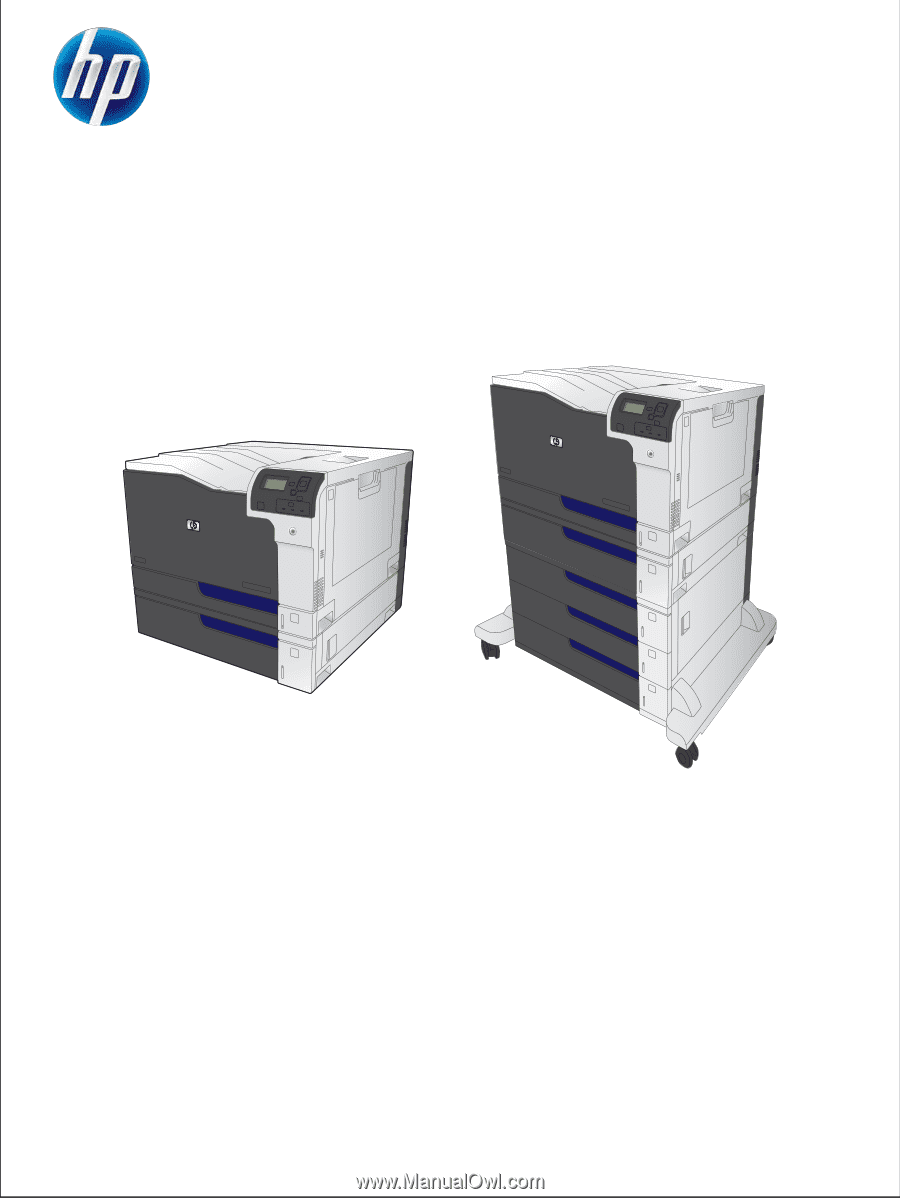
HP COLOR LASERJET ENTERPRISE CP5520
PRINTER SERIES
Service Manual