HP Color LaserJet Enterprise CP5525 Service Manual - Page 534
Jams in Tray 1, Tray 2 and internal paper path, Table 3-53
 |
View all HP Color LaserJet Enterprise CP5525 manuals
Add to My Manuals
Save this manual to your list of manuals |
Page 534 highlights
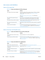
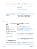
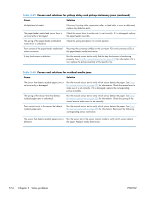
Table 3-53 Causes and solutions for duplex repick jams (continued) Cause Solution The duplex flapper is damaged or malfunctioning. Replace the paper delivery assembly. See Paper delivery assembly on page 184. The duplex repick roller is worn or damaged. Replace the registration sensor assembly. See Registration sensor assembly on page 142. The duplex repick clutch is defective. Run the solenoid drive test in component test (see Component tests on page 314)to verify that the duplex repick clutch is functioning properly. If it is not, replace the duplex drive assembly. See Duplex drive assembly (duplex models) on page 187. Table 3-54 Causes and solutions for residual media jams Cause Solution Poor contact of the fuser loop-sensor connector and fuser loop sensor 1 and 2. Reconnect the connectors of the fuser loop sensor 1 and 2 (J13) and the connector (J131) on the DC controller PCA. The loop sensor is defective. Run the manual sensor test. See Fuser loop sensors 1 and 2 (PS7 and PS8) on page 295 for information. If the sensor is defective, replace fuser. See Fuser on page 93. The spring of the fuser-output-sensor lever is unhooked. Check the spring of the fuser and right door and place it in the correct position. The fuser-output sensor lever is damaged. Replace the sensor (PS6). Poor contact of the fuser-output sensor connector. Reconnect connector (J1055) of the fuser-output sensor and connector (J131) on the DC controller PCA. The fuser-output sensor is defective. Run the manual sensor test to make sure the fuser-delivery sensor is functioning properly. See Fuser output sensor (PS6) on page 297 for information. If the sensor is defective, replace the fuser. See Fuser on page 93. The duplex pickup sensor lever is damaged. Replace the right door assembly. See Right-door assembly on page 126. NOTE: Even if jammed paper is visible in Tray 1, clear the jam from the inside of the product by opening the right door. Jams in Tray 1, Tray 2 and internal paper path Table 3-55 Causes and solutions for pickup delay jam 1: tray pickup Cause Solution The tray 1 pick up roller or the tray 1 separation pad is worn or deformed. Replace the tray 1 pickup roller and separation pad. See Pickup roller (Tray 1) on page 94 and Separation pad (Tray 1) on page 95. Replace the right door. See Right-door assembly on page 126. Poor contact of the tray 1 media-presencesensor connector Reconnect the connectors of the tray media-feed sensor intermediate connectors (J531L and J531D), and the connector (J152) on the DC controller. Poor contact of the TOP sensor connector. Reconnect the intermediate connector (J554L and J554D) of the TOP sensor and connector (J122) on the DC controller PCA. 510 Chapter 3 Solve problems ENWW
-
 1
1 -
2
-
3
-
4
-
5
-
6
-
7
-
8
-
9
-
10
-
11
-
12
-
13
-
14
-
15
-
16
-
17
-
18
-
19
-
20
-
21
-
22
-
23
-
24
-
25
-
26
-
27
-
28
-
29
-
30
-
31
-
32
-
33
-
34
-
35
-
36
-
37
-
38
-
39
-
40
-
41
-
42
-
43
-
44
-
45
-
46
-
47
-
48
-
49
-
50
-
51
-
52
-
53
-
54
-
55
-
56
-
57
-
58
-
59
-
60
-
61
-
62
-
63
-
64
-
65
-
66
-
67
-
68
-
69
-
70
-
71
-
72
-
73
-
74
-
75
-
76
-
77
-
78
-
79
-
80
-
81
-
82
-
83
-
84
-
85
-
86
-
87
-
88
-
89
-
90
-
91
-
92
-
93
-
94
-
95
-
96
-
97
-
98
-
99
-
100
-
101
-
102
-
103
-
104
-
105
-
106
-
107
-
108
-
109
-
110
-
111
-
112
-
113
-
114
-
115
-
116
-
117
-
118
-
119
-
120
-
121
-
122
-
123
-
124
-
125
-
126
-
127
-
128
-
129
-
130
-
131
-
132
-
133
-
134
-
135
-
136
-
137
-
138
-
139
-
140
-
141
-
142
-
143
-
144
-
145
-
146
-
147
-
148
-
149
-
150
-
151
-
152
-
153
-
154
-
155
-
156
-
157
-
158
-
159
-
160
-
161
-
162
-
163
-
164
-
165
-
166
-
167
-
168
-
169
-
170
-
171
-
172
-
173
-
174
-
175
-
176
-
177
-
178
-
179
-
180
-
181
-
182
-
183
-
184
-
185
-
186
-
187
-
188
-
189
-
190
-
191
-
192
-
193
-
194
-
195
-
196
-
197
-
198
-
199
-
200
-
201
-
202
-
203
-
204
-
205
-
206
-
207
-
208
-
209
-
210
-
211
-
212
-
213
-
214
-
215
-
216
-
217
-
218
-
219
-
220
-
221
-
222
-
223
-
224
-
225
-
226
-
227
-
228
-
229
-
230
-
231
-
232
-
233
-
234
-
235
-
236
-
237
-
238
-
239
-
240
-
241
-
242
-
243
-
244
-
245
-
246
-
247
-
248
-
249
-
250
-
251
-
252
-
253
-
254
-
255
-
256
-
257
-
258
-
259
-
260
-
261
-
262
-
263
-
264
-
265
-
266
-
267
-
268
-
269
-
270
-
271
-
272
-
273
-
274
-
275
-
276
-
277
-
278
-
279
-
280
-
281
-
282
-
283
-
284
-
285
-
286
-
287
-
288
-
289
-
290
-
291
-
292
-
293
-
294
-
295
-
296
-
297
-
298
-
299
-
300
-
301
-
302
-
303
-
304
-
305
-
306
-
307
-
308
-
309
-
310
-
311
-
312
-
313
-
314
-
315
-
316
-
317
-
318
-
319
-
320
-
321
-
322
-
323
-
324
-
325
-
326
-
327
-
328
-
329
-
330
-
331
-
332
-
333
-
334
-
335
-
336
-
337
-
338
-
339
-
340
-
341
-
342
-
343
-
344
-
345
-
346
-
347
-
348
-
349
-
350
-
351
-
352
-
353
-
354
-
355
-
356
-
357
-
358
-
359
-
360
-
361
-
362
-
363
-
364
-
365
-
366
-
367
-
368
-
369
-
370
-
371
-
372
-
373
-
374
-
375
-
376
-
377
-
378
-
379
-
380
-
381
-
382
-
383
-
384
-
385
-
386
-
387
-
388
-
389
-
390
-
391
-
392
-
393
-
394
-
395
-
396
-
397
-
398
-
399
-
400
-
401
-
402
-
403
-
404
-
405
-
406
-
407
-
408
-
409
-
410
-
411
-
412
-
413
-
414
-
415
-
416
-
417
-
418
-
419
-
420
-
421
-
422
-
423
-
424
-
425
-
426
-
427
-
428
-
429
-
430
-
431
-
432
-
433
-
434
-
435
-
436
-
437
-
438
-
439
-
440
-
441
-
442
-
443
-
444
-
445
-
446
-
447
-
448
-
449
-
450
-
451
-
452
-
453
-
454
-
455
-
456
-
457
-
458
-
459
-
460
-
461
-
462
-
463
-
464
-
465
-
466
-
467
-
468
-
469
-
470
-
471
-
472
-
473
-
474
-
475
-
476
-
477
-
478
-
479
-
480
-
481
-
482
-
483
-
484
-
485
-
486
-
487
-
488
-
489
-
490
-
491
-
492
-
493
-
494
-
495
-
496
-
497
-
498
-
499
-
500
-
501
-
502
-
503
-
504
-
505
-
506
-
507
-
508
-
509
-
510
-
511
-
512
-
513
-
514
-
515
-
516
-
517
-
518
-
519
-
520
-
521
-
522
-
523
-
524
-
525
-
526
-
527
-
528
-
 529
529 -
 530
530 -
 531
531 -
 532
532 -
 533
533 -
 534
534 -
 535
535 -
 536
536 -
 537
537 -
 538
538 -
 539
539 -
540
-
541
-
542
-
543
-
544
-
545
-
546
-
547
-
548
-
549
-
550
-
551
-
552
-
553
-
554
-
555
-
556
-
557
-
558
-
559
-
560
-
561
-
562
-
563
-
564
-
565
-
566
-
567
-
568
-
569
-
570
-
571
-
572
-
573
-
574
-
575
-
576
-
577
-
578
-
579
-
580
-
581
-
582
-
583
-
584
-
585
-
586
-
587
-
588
-
589
-
590
-
591
-
592
-
593
-
594
-
595
-
596
-
597
-
598
-
599
-
600
-
601
-
602
-
603
-
604
-
605
-
606
-
607
-
608
-
609
-
610
-
611
-
612
-
613
-
614
-
615
-
616
-
617
-
618
-
619
-
620
-
621
-
622
-
623
-
624
-
625
-
626
-
627
-
628
-
629
-
630
-
631
-
632
-
633
-
634
-
635
-
636
-
637
-
638
-
639
-
640
-
641
-
642
-
643
-
644
-
645
-
646
-
647
-
648
-
649
-
650
-
651
-
652
-
653
-
654
-
655
-
656
-
657
-
658
-
659
-
660
-
661
-
662
-
663
-
664
-
665
-
666
-
667
-
668
-
669
-
670
-
671
-
672
-
673
-
674
-
675
-
676
-
677
-
678
-
679
-
680
-
681
-
682
-
683
-
684
-
685
-
686
 |
 |