HP DL740 HP ProLiant DL740 Server User Guide
HP DL740 - ProLiant - 4 GB RAM Manual
 |
UPC - 808736765770
View all HP DL740 manuals
Add to My Manuals
Save this manual to your list of manuals |
HP DL740 manual content summary:
- HP DL740 | HP ProLiant DL740 Server User Guide - Page 1
HP ProLiant DL740 Server User Guide June 2003 (Second Edition) Part Number 270854-002 - HP DL740 | HP ProLiant DL740 Server User Guide - Page 2
change without notice. The warranties for HP products are set forth in the express limited warranty statements accompanying such products. Nothing herein should be construed as constituting an additional warranty. HP ProLiant DL740 Server User Guide June 2003 (Second Edition) Part Number 270854-002 - HP DL740 | HP ProLiant DL740 Server User Guide - Page 3
ProLiant DL740 Servers 1-1 Standard Features ...1-6 Processors ...1-6 Hot Plug RAID Memory 1-7 PCI-X Technology 1-10 PCI Hot Plug...1-10 Network Interface Controllers 1-11 Disk Controller ...1-11 Internal Hot-Plug Drive Bays 1-12 Universal Media Bay 1-12 HP ProLiant DL740 Server User Guide - HP DL740 | HP ProLiant DL740 Server User Guide - Page 4
Requirements 2-3 Power Requirements 2-5 Grounding Requirements 2-7 Temperature Requirements 2-8 Shipping Box Contents ...2-9 Rack Considerations ...2-10 Rack Stability ...2-10 Warnings and Precautions 2-11 Preparing the Rack for Server Installation 2-13 iv HP ProLiant DL740 Server User Guide - HP DL740 | HP ProLiant DL740 Server User Guide - Page 5
RAID Memory 5-2 Memory Cartridge Overview 5-2 Memory Cartridge Guidelines 5-3 Memory Cartridge LED Indicators 5-5 Accessing the DIMMs 5-8 DIMM Overview ...5-9 Installing DIMMs in the Memory Cartridge 5-11 Hot Plug RAID Memory Operating System Support 5-12 HP ProLiant DL740 Server User Guide - HP DL740 | HP ProLiant DL740 Server User Guide - Page 6
Server Peripheral Devices ...6-1 Power Cables ...6-3 Cable Management System 6-5 Chapter 7 Server Power System Power Overview 7-2 Power Supplies ...7-3 Power Supply LED Indicators 7-4 System Interconnect Status Indicators 7-5 Powering Up the Server 7-7 vi HP ProLiant DL740 Server User Guide - HP DL740 | HP ProLiant DL740 Server User Guide - Page 7
Utility 9-10 Viewing the IML with Insight Manager 7 9-11 Insight Manager 7...9-13 Survey Utility ...9-14 Array Configuration Utility 9-15 Step 1-Running ACU as a Local-Only Application 9-15 Step 2-Running ACU as a Service With Remote Accessibility 9-15 HP ProLiant DL740 Server User Guide vii - HP DL740 | HP ProLiant DL740 Server User Guide - Page 8
Switches (Front and Rear D-2 System Interconnect LED Indicators D-3 System Attention LED Indicators D-5 System Activity LED Indicators D-6 Hot-Plug SCSI Hard Drive LED Indicators D-7 Power Supply LED Indicators D-9 Hot-Plug Fan LED Indicators D-11 viii HP ProLiant DL740 Server User Guide - HP DL740 | HP ProLiant DL740 Server User Guide - Page 9
E Troubleshooting Information Server Startup Problems E-2 Diagnosis Steps ...E-4 Problems After Initial Boot E-12 Redundant ROM Images E-15 Appendix F Server Specifications Server Specifications ...F-1 Appendix G System Battery Internal Battery...G-1 Index HP ProLiant DL740 Server User Guide ix - HP DL740 | HP ProLiant DL740 Server User Guide - Page 10
by-step instructions for installation, and reference information for operation, troubleshooting, and future upgrades for the ProLiant DL740 server. Audience Assumptions This guide is for the person who installs, administers, and troubleshoots servers. HP assumes you are qualified in the servicing of - HP DL740 | HP ProLiant DL740 Server User Guide - Page 11
shock hazards. The area contains no user or field serviceable parts. Do not open for any reason. These symbols, on power supplies or systems, indicate that the equipment is supplied by multiple sources of power. WARNING: To reduce manual material handling. xii HP ProLiant DL740 Server User Guide - HP DL740 | HP ProLiant DL740 Server User Guide - Page 12
attached to the rack if it is a single-rack installation. • The racks are coupled together in multiple-rack installations. • Only one component is extended at a time. A rack may become unstable to emphasize or supplement important points of the main text. HP ProLiant DL740 Server User Guide xiii - HP DL740 | HP ProLiant DL740 Server User Guide - Page 13
cartridge operation label System status LED indicators label Removing power and media module label Front components label Item 6 7 8 9 Component I/O board configuration label System board components label Rear connectors label Removing host module label xiv HP ProLiant DL740 Server User Guide - HP DL740 | HP ProLiant DL740 Server User Guide - Page 14
Controller User Guide - ROM-Based Setup Utility User Guide - Servers Troubleshooting Guide - PCI Hot Plug Administration Guide - Integrated Lights-Out User Guide - Server Online Reference Guide - Hot Plug RAID Multimedia Virtual Tour for ProLiant DL740 Servers multimedia demo • ProLiant DL740 Power - HP DL740 | HP ProLiant DL740 Server User Guide - Page 15
Add-on boards or hardware • Third-party hardware or software • Operating system type and revision level HP Website The HP website has information on this product as well as the latest drivers and flash ROM images. You can access the HP website at www.hp.com. xvi HP ProLiant DL740 Server User Guide - HP DL740 | HP ProLiant DL740 Server User Guide - Page 16
guaranteed service providers. For U.S. ordering information, refer to the services website: h18005.www1.hp.com/services/carepaq/us/install/ For worldwide ordering information, refer to the services website: h18005.www1.hp.com/services/carepaq/global/ HP ProLiant DL740 Server User Guide xvii - HP DL740 | HP ProLiant DL740 Server User Guide - Page 17
About This Guide Reader's Comments HP welcomes your comments on this guide. Please send your comments and suggestions by e-mail to [email protected]. xviii HP ProLiant DL740 Server User Guide - HP DL740 | HP ProLiant DL740 Server User Guide - Page 18
, all with PCI Hot Plug capability. • Drive performance enhanced with an embedded Smart Array 5i Controller and Ultra3 hard drives. • Integrated Lights-Out (iLO) Standard. • Two embedded Gigabit Ethernet network interface controllers (NICs) with PXE support. HP ProLiant DL740 Server User Guide 1-1 - HP DL740 | HP ProLiant DL740 Server User Guide - Page 19
Processor Power Modules (PPM) • PCI Hot Plug slots • Redundant hot-pluggable power supplies • Redundant hot-pluggable fans • Redundant NIC support • Smart Array 5i Controller • Disk drive fault tolerance • Automatic Server Recovery (ASR-2) • Dual power cords Server management and configuration tools - HP DL740 | HP ProLiant DL740 Server User Guide - Page 20
host module and the power and media module. Refer to Figure 1-1, Figure 1-2, and Figure 1-3 for identification of these modules and other components. Figure 1-1: Server front view-module location Item Description 1 Power and media module 2 Host module HP ProLiant DL740 Server User Guide 1-3 - HP DL740 | HP ProLiant DL740 Server User Guide - Page 21
Server Features Figure 1-2: Server front view-module components Item Description 1 Power supply 1 2 Hot-plug hard drives 3 Universal media bay 4 Power supply 2 1-4 HP ProLiant DL740 Server User Guide - HP DL740 | HP ProLiant DL740 Server User Guide - Page 22
Server Features Figure 1-3: Server rear view-module components Item Description 1 System fans 2 AC power ports 3 I/O expansion slots 4 External connectors HP ProLiant DL740 Server User Guide 1-5 - HP DL740 | HP ProLiant DL740 Server User Guide - Page 23
times and increased throughput and performance of the memory subsystem. Specifically, integrated Level 3 cache, which is only available on the Xeon processor MP, provides a high-bandwidth path to memory, increasing throughput for large server workloads. 1-6 HP ProLiant DL740 Server User Guide - HP DL740 | HP ProLiant DL740 Server User Guide - Page 24
down the server. This feature requires operating system support and drivers. • Memory hot-upgrade-Allows the upgrade of existing DIMMs with larger-capacity DIMMs without powering down the server. This feature requires operating system support and HP drivers. HP ProLiant DL740 Server User Guide 1-7 - HP DL740 | HP ProLiant DL740 Server User Guide - Page 25
Server Features The Hot Plug RAID Memory cartridges are located on the inner right side of the host module. Each memory cartridge contains up to eight DIMMs. Each cartridge has a protective cover, and a latch and lock. Figure 1-4: Memory cartridge location 1-8 HP ProLiant DL740 Server User Guide - HP DL740 | HP ProLiant DL740 Server User Guide - Page 26
DIMM part number. All DIMMs in a bank must have the same part number, as indicated by the following example: 123456-12x All numbers except the last (designated by x) must match for DIMMs to be considered the same. • Cartridge and DIMM diagnostic information HP ProLiant DL740 Server User Guide 1-9 - HP DL740 | HP ProLiant DL740 Server User Guide - Page 27
Hot Plug. A PCI Hot Plug button is located above each PCI/PCI-X slot, providing PCI Hot Plug control directly at the server without the use of the PCI Hot Plug utility software. For more information about PCI Hot Plug, refer to the server documentation CD. 1-10 HP ProLiant DL740 Server User Guide - HP DL740 | HP ProLiant DL740 Server User Guide - Page 28
with HP ProLiant servers, AlphaServer, and StorageWorks Enclosure 4200 solutions. Ultra320 SCSI hard drives will run at Ultra3 speeds unless you install an optional Ultra320 Array Controller and the Twisted Pair Cable Array Bypass kit included with the system. HP ProLiant DL740 Server User Guide - HP DL740 | HP ProLiant DL740 Server User Guide - Page 29
supplies are load balancing. • The ProLiant DL740 server supports up to two power supplies. Refer to the "Power Requirements" section of Chapter 2 to determine power supply requirements. • Power supplies must be run at highline (200-240 VAC) for redundancy. 1-12 HP ProLiant DL740 Server User Guide - HP DL740 | HP ProLiant DL740 Server User Guide - Page 30
standard in the server include: • Serial connector • Video port • Keyboard connector • Mouse connector • Two RJ-45 server local area network (LAN) connectors (10/100/1000 Ethernet) • iLO LAN connector (10/100 management) • Universal serial bus (USB) port HP ProLiant DL740 Server User Guide 1-13 - HP DL740 | HP ProLiant DL740 Server User Guide - Page 31
Features The ProLiant DL740 server supports a wide range of server hardware options. HP server options are available from an HP authorized reseller or HP authorized service provider. Additional information about HP servers and options can be found in the QuickSpecs on the HP website. This guide also - HP DL740 | HP ProLiant DL740 Server User Guide - Page 32
to configure the server and load the system software, thereby achieving a wellintegrated server to ensure maximum dependability and supportability. For information about SmartStart, refer to the ProLiant Essentials Foundation Pack included in the shipping box. HP ProLiant DL740 Server User Guide - HP DL740 | HP ProLiant DL740 Server User Guide - Page 33
, French, German, Italian, Spanish, and Japanese languages. NOTE: Systems that use RBSU do not support the System Configuration Utility. For more information on using RBSU, refer to the ROM-Based Setup Utility User Guide located on the documentation CD. 1-16 HP ProLiant DL740 Server User Guide - HP DL740 | HP ProLiant DL740 Server User Guide - Page 34
integrated component in the ProLiant DL740 server and provides: • Text-based console • Virtual power button and reset • Virtual indicators • Event logs (IML and iLO log) • Remote Diagnostics (iLO and server) • Automatic Server Recovery • Agent integration HP ProLiant DL740 Server User Guide 1-17 - HP DL740 | HP ProLiant DL740 Server User Guide - Page 35
has redundant boot block ROM that allows you to upgrade the boot block image without the risk of compromising the server. This redundancy enables you to recover the permanent factory boot block ROM image if the current boot block ROM has been corrupted. 1-18 HP ProLiant DL740 Server User Guide - HP DL740 | HP ProLiant DL740 Server User Guide - Page 36
HP Smart Components for ROM Flash include installation logic that automatically checks for hardware, firmware, and operating system dependencies, installing only the correct ROM upgrades required by each target server RAID 5 only allows one drive failure. HP ProLiant DL740 Server User Guide 1-19 - HP DL740 | HP ProLiant DL740 Server User Guide - Page 37
for Linux • Insight Diagnostics • Lights-Out Drivers and Agents for Linux • NIC Agents for Linux • Red Hat GL Utility Toolkit (GLUT) • Server Management Drivers and Agents These utilities are provided on the ProLiant Support Pack for Linux operating system. 1-20 HP ProLiant DL740 Server User Guide - HP DL740 | HP ProLiant DL740 Server User Guide - Page 38
• Server performance and fault condition monitoring • Server security and configuration control • Remote control of the server • Rapid recovery services For more information on Insight Manager 7, refer to the Management CD that shipped with your server. HP ProLiant DL740 Server User Guide 1-21 - HP DL740 | HP ProLiant DL740 Server User Guide - Page 39
Memory Configuration Error Diagnostics • Server diagnostics (DIAGS) • ROMPaq utilities to upgrade flash ROMs • ACU • IML For information about diagnostic tools, refer to either the HP Servers Troubleshooting Guide on the server documentation CD or to Appendix E. 1-22 HP ProLiant DL740 Server User - HP DL740 | HP ProLiant DL740 Server User Guide - Page 40
and mouse without exiting the application. The application remains in view on the monitor screen, but cannot be accessed. • Serial interface control-Disables the serial port. When disabled, all data transfer through the integrated serial port is blocked. HP ProLiant DL740 Server User Guide 1-23 - HP DL740 | HP ProLiant DL740 Server User Guide - Page 41
Server Features Hardware Security The ProLiant DL740 server has a switch on the I/O board that establishes the following hardware security features: • Configuration (NVRAM) lock-Disallows configuration changes when enabled by preventing nonvolatile memory from being modified. • Diskette boot control - HP DL740 | HP ProLiant DL740 Server User Guide - Page 42
Server Features Routine Maintenance For information about routine maintenance and safety precautions, refer to the server documentation CD included with your server. HP ProLiant DL740 Server User Guide 1-25 - HP DL740 | HP ProLiant DL740 Server User Guide - Page 43
Parts, Labor, and On-Site Limited Warranty with next business day response • Pre-Failure Warranty on processors, memory, and hard drives (requires installation of Insight Manager 7) For additional service and support offerings, visit the HP website: www.hp.com 1-26 HP ProLiant DL740 Server User - HP DL740 | HP ProLiant DL740 Server User Guide - Page 44
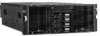
2 Installing the Server in a Rack This chapter specifies the procedures required to install a ProLiant DL740 server in an HP or industry-standard 19-inch rack. Figure 2-1: ProLiant DL740 server HP ProLiant DL740 Server User Guide 2-1 - HP DL740 | HP ProLiant DL740 Server User Guide - Page 45
the chassis in the rack and replace the modules. NOTE: Refer to the rack template included with the server for more details on installing the server into a rack. 5. Connect the keyboard, mouse, monitor, network, storage, and power cords. Refer to Chapter 6. 2-2 HP ProLiant DL740 Server User Guide - HP DL740 | HP ProLiant DL740 Server User Guide - Page 46
openings. When vertical space in the rack is not filled by a server or rack component, the gaps between the components cause changes in airflow through the rack and across the servers. Cover all gaps with blanking panels to maintain proper airflow. HP ProLiant DL740 Server User Guide 2-3 - HP DL740 | HP ProLiant DL740 Server User Guide - Page 47
of the rack must be a minimum of 7 cm (2.75 inches). CAUTION: When using a Compaq branded 7000 Series rack, you must install the high airflow rack door insert [P/N 327281-B21 (42U) or P/N 157847-B21 (22U)] to provide proper front-to-back airflow and cooling. 2-4 HP ProLiant DL740 Server User Guide - HP DL740 | HP ProLiant DL740 Server User Guide - Page 48
using 110V input line voltage on the ProLiant DL740 server. To estimate the power requirements for a specific server configuration, use the ProLiant DL740 Server Power Calculator located on the ActiveAnswers Online Solutions website: activeanswers.compaq.com HP ProLiant DL740 Server User Guide 2-5 - HP DL740 | HP ProLiant DL740 Server User Guide - Page 49
, which means that no switch is needed to select the appropriate line voltage. NOTE: Power supplies provide 1100 watts of power to the system from highline (200−240 VAC) input line voltage and 800 watts of power from lowline (100−120 VAC) input line voltage. 2-6 HP ProLiant DL740 Server User Guide - HP DL740 | HP ProLiant DL740 Server User Guide - Page 50
Power Distribution Unit (PDU) that provides a supplementary ground conductor. This supplementary ground conductor should be permanently connected to a suitable building ground terminal. The use of common power outlet strips for this equipment is not recommended. HP ProLiant DL740 Server User Guide - HP DL740 | HP ProLiant DL740 Server User Guide - Page 51
to the rack-mountable ProLiant DL740 servers or increase the internal rack temperature beyond the HP specified maximum rating. • Be sure that the Manufacturer's TMRA for the optional equipment is not exceeded when the equipment is installed in the rack. 2-8 HP ProLiant DL740 Server User Guide - HP DL740 | HP ProLiant DL740 Server User Guide - Page 52
software packs, including ProLiant Essentials Foundation Pack, reference information, and software products • Hardware kit - Rack template contains rack installation instructions - Server rack rails - Cable management system - Integrated Array Bypass kit In addition to the supplied items, you may - HP DL740 | HP ProLiant DL740 Server User Guide - Page 53
kg (210 lb) minimum weight. In addition, ballast kits should be installed if any single system component weighs over 45 kg (100 lb) such that a minimum of 91 kg (200 lb) of ballast and equipment remains in place when the component is extended from the rack. 2-10 HP ProLiant DL740 Server User Guide - HP DL740 | HP ProLiant DL740 Server User Guide - Page 54
assistance to lift and stabilize the chassis during installation or removal. • Understand that the product will be unstable when not fastened to the rails. • Remove all hot-plug power supplies and drives to reduce the overall weight of the product. HP ProLiant DL740 Server User Guide 2-11 - HP DL740 | HP ProLiant DL740 Server User Guide - Page 55
HP website or ordered with the Rack Resource CD Kit) • Rack Products Documentation CD (available on the HP website or ordered with the Rack Resource CD Kit) • The Rack 7000/4000 Series Rack Resource CD Kit ships with all Compaq 7000 and 4000 Series Racks. 2-12 HP ProLiant DL740 Server User Guide - HP DL740 | HP ProLiant DL740 Server User Guide - Page 56
installing the rack rail assemblies. To remind you of the proper placement of the server in the rack, refer to the Rack Builder report you printed when you planned your rack configuration with the Rack Builder tools provided with your Compaq branded rack. HP ProLiant DL740 Server User Guide 2-13 - HP DL740 | HP ProLiant DL740 Server User Guide - Page 57
Measuring with the template 3. Align the template so that the sides of the template are even with the sides of the rack. Tick marks on the vertical rails of the rack designate U-spaces in the rack configuration and help you maintain the proper alignment. 2-14 HP ProLiant DL740 Server User Guide - HP DL740 | HP ProLiant DL740 Server User Guide - Page 58
of the template on the rear of the rack. IMPORTANT: On the rear of the rack, make pencil marks on the inside of the vertical rails. These markings guide you in installing rack rails in the interior of the rack frame. 8. Remove the template from the rack. HP ProLiant DL740 Server User Guide 2-15 - HP DL740 | HP ProLiant DL740 Server User Guide - Page 59
rail assemblies in the rack: 1. From the front of the rack, identify the rear rack holes on the inside of the vertical rack that you marked with the template. 2. Pull the rail compression lever toward you. Figure 2-3: Pulling the rail compression lever 2-16 HP ProLiant DL740 Server User Guide - HP DL740 | HP ProLiant DL740 Server User Guide - Page 60
the Server in a Rack 3. Insert the two rail tabs from the end of the rack rail assembly into the marked holes on the inside of the rear of the rack. Figure 2-4: Inserting the rail tabs on the rear of the rack 4. Adjust the rack rail depth by sliding it forward. HP ProLiant DL740 Server User Guide - HP DL740 | HP ProLiant DL740 Server User Guide - Page 61
6. Release the rail compression lever to seat the tabs in the rack post. 7. Repeat steps 1 through 6 for the other rail. Preparing the Server for Rack Installation To prepare the server for rack installation: • Attach the server rails • Lighten the chassis 2-18 HP ProLiant DL740 Server User Guide - HP DL740 | HP ProLiant DL740 Server User Guide - Page 62
and lock the rail into place. Figure 2-6: Attaching a server rail to the chassis IMPORTANT: Be sure that the first rail is firmly anchored to the chassis before attaching the second rail. 3. Repeat steps 1 and 2 to secure the second rail to the server. HP ProLiant DL740 Server User Guide 2-19 - HP DL740 | HP ProLiant DL740 Server User Guide - Page 63
at least two people handle the modules together. 1. Remove the host module as shown in the "Removing the Host Module" section of Chapter 3. 2. Remove the power and media module as shown in the "Removing the Power and Media Module" section of Chapter 3. 2-20 HP ProLiant DL740 Server User Guide - HP DL740 | HP ProLiant DL740 Server User Guide - Page 64
the rack. To install the server in the rack: 1. Pull the inner slide rail forward from each rack rail assembly until it locks into place (1). 2. Slide the inner bearing brace forward until it stops (2). Figure 2-7: Locking the inner slide rails into place HP ProLiant DL740 Server User Guide 2-21 - HP DL740 | HP ProLiant DL740 Server User Guide - Page 65
levers engage the rack rail assemblies (3). Figure 2-8: Loading the server onto the rack rails CAUTION: Keep the server parallel to the floor when sliding the server rails into the standard rack rails. Tilting the server up or down can damage the rails. 2-22 HP ProLiant DL740 Server User Guide - HP DL740 | HP ProLiant DL740 Server User Guide - Page 66
the rack until the rack assembly is fully extended and the rails lock. This action initializes the rail lock for future use. 7. Press the rack levers at the front of the server rails to release the lock, and slide the server all the way back into the rack. HP ProLiant DL740 Server User Guide 2-23 - HP DL740 | HP ProLiant DL740 Server User Guide - Page 67
to secure the server to the rack. Figure 2-10: Tightening the thumbscrews Rack Template The HP ProLiant DL740 server rack template has procedures detailing the rack installation of the ProLiant DL740 server and how to install the cable management hardware. 2-24 HP ProLiant DL740 Server User Guide - HP DL740 | HP ProLiant DL740 Server User Guide - Page 68
3 Server Access The ProLiant DL740 server provides easy access to all internal components for installation and maintenance. This chapter provides details concerning system power and power supply indicators and removal of the server modules. HP ProLiant DL740 Server User Guide 3-1 - HP DL740 | HP ProLiant DL740 Server User Guide - Page 69
information pertaining to PCI Hot Plug and hot-plug fan access, refer to Chapter 5. CAUTION: Do not attempt to remove either of the modules while power is applied to the system. They are not hot-pluggable. Immediate system shutdown and data loss will occur. 3-2 HP ProLiant DL740 Server User Guide - HP DL740 | HP ProLiant DL740 Server User Guide - Page 70
unit identification switches to quickly identify one or more servers that require service or maintenance. Figure 3-1 displays the locations of the Unit Identification LED switches on the front and rear of the server. Figure 3-1: Locating the UID switch LED HP ProLiant DL740 Server User Guide 3-3 - HP DL740 | HP ProLiant DL740 Server User Guide - Page 71
Server Access Accessing the Host Module To access the host module to install or replace hot-plug fans or PCI Hot Plug boards: 1. Slide the chassis out of the rack. 2. the hot-plug fans and PCI/PCI-X Hot Plug expansion boards as described in Chapter 5. 3-4 HP ProLiant DL740 Server User Guide - HP DL740 | HP ProLiant DL740 Server User Guide - Page 72
gain access to the host module and the processor boards. HP recommends removing the processor boards to lighten the module. WARNING: To reduce the risk of personal injury from hot surfaces, allow the internal system components to cool before touching them. HP ProLiant DL740 Server User Guide 3-5 - HP DL740 | HP ProLiant DL740 Server User Guide - Page 73
Server Access 5. Push the processor board lever latch down to release the lever (1). 6. Lift the processor board lever up (2) to release the board, and lift the processor board out of the module (3). Figure 3-3: Removing the processor board 3-6 HP ProLiant DL740 Server User Guide - HP DL740 | HP ProLiant DL740 Server User Guide - Page 74
rack until the chassis makes contact with the rail stop. NOTE: The top panel labels provide instructions about installing expansion boards, setting switches, and installing hot-plug fans, along with information about PCI Hot Plug. Refer to Chapter 5 for hot-plug procedures. HP ProLiant DL740 Server - HP DL740 | HP ProLiant DL740 Server User Guide - Page 75
Table 3-2: Host Module Components Item 1 2 3 4 5 Component Processor board 1 Processor board 2 Memory cartridge 1 Memory cartridge 2 Memory cartridge 3 Item 6 7 8 9 10 Component Memory cartridge 4 Memory cartridge 5 I/O board System fan 2 System fan 1 3-8 HP ProLiant DL740 Server User Guide - HP DL740 | HP ProLiant DL740 Server User Guide - Page 76
Server Access The system board is located in the bottom of the host module. Refer to Table 3-3 to identify components on the system board. Figure 3-6: System board components HP ProLiant DL740 Server User Guide 3-9 - HP DL740 | HP ProLiant DL740 Server User Guide - Page 77
cartridge 3 connector Memory cartridge 4 connector Memory cartridge 5 connector Processor board 2 connector Processor board 1 connector Remote Insight board connector System/midplane board connector I/O board connector System battery iLO diagnostic LEDs 3-10 HP ProLiant DL740 Server User Guide - HP DL740 | HP ProLiant DL740 Server User Guide - Page 78
the power and media module: 1. If the server is on, place the computer in standby mode and disconnect the power cords. Refer to Chapter 7. 2. Unseat or remove the host module from the server chassis. 3. Remove the power supplies from the front of the module. HP ProLiant DL740 Server User Guide - HP DL740 | HP ProLiant DL740 Server User Guide - Page 79
supplies weigh 4 kg (9 lbs) each. NOTE: When you remove the power supply, a spring-loaded trap door closes to block the opening. This door preserves the air path required to cool the internal components of the server. Figure 3-7: Removing a power supply 3-12 HP ProLiant DL740 Server User Guide - HP DL740 | HP ProLiant DL740 Server User Guide - Page 80
Figure 3-2 7. Slide the module release levers (1) on the power and media module, as shown in Figure 3-8. 8. Pull the power and media module (2) out of the chassis until it encounters the module stop latches. Figure 3-8: Releasing the power and media module HP ProLiant DL740 Server User Guide 3-13 - HP DL740 | HP ProLiant DL740 Server User Guide - Page 81
the power and media module WARNING: To reduce the risk of personal injury from hot surfaces, allow the internal system components to cool before touching them. 10. To reassemble the server, slide the module into the chassis until the levers snap into place. 3-14 HP ProLiant DL740 Server User Guide - HP DL740 | HP ProLiant DL740 Server User Guide - Page 82
SCSI ID 2 9 4 Ultra3 hard drive SCSI ID 3 10 5 Power supply 1 11 6 Power On/Standby switch Component Universal media bay, with DVD/CD-ROM drive 1.44 MB diskette drive Unit identification switch LED Universal media bay eject button Power supply 2 HP ProLiant DL740 Server User Guide 3-15 - HP DL740 | HP ProLiant DL740 Server User Guide - Page 83
option upgrades that require the system power to be off. HP recommends that you use the documentation provided with the hardware option for complete installation instructions. You can also refer to the HP ProLiant DL740 Server Supplemental Setup Guide included in the shipping box or to the labels - HP DL740 | HP ProLiant DL740 Server User Guide - Page 84
Installing Hardware Options, Non-Hot-Plug Intel Xeon Processor MP The ProLiant DL740 server supports either four or eight processors. • All processors installed on a processor Processor 1 must always be installed to properly terminate the processor bus. 4-2 HP ProLiant DL740 Server User Guide - HP DL740 | HP ProLiant DL740 Server User Guide - Page 85
Installing Hardware Options, Non-Hot-Plug Figure 4-1: Processor board layout Item Description 1 Intel Xeon processor MP in socket 1 2 Intel Xeon processor MP in socket 2 3 Intel Xeon processor MP in socket 3 4 Intel Xeon processor MP in socket 4 HP ProLiant DL740 Server User Guide 4-3 - HP DL740 | HP ProLiant DL740 Server User Guide - Page 86
Installing Hardware Options, Non-Hot-Plug Installing a Processor Board The ProLiant DL740 server is capable of supporting up to eight Intel Xeon processors MP and is shipped with four processors installed. The ProLiant DL740 server has space for two processor boards in the host module. Figure 4-2: - HP DL740 | HP ProLiant DL740 Server User Guide - Page 87
. 6. Remove the processor board air baffle by pressing in the release tab (1) while pulling the air baffle up (2). Figure 4-3: Removing the processor board air baffle HP ProLiant DL740 Server User Guide 4-5 - HP DL740 | HP ProLiant DL740 Server User Guide - Page 88
Installing Hardware Options, Non-Hot-Plug 7. Insert the place to provide optimal airflow. 10. Connect all power cords and power up the server. If the system does not power up, verify that the system interconnect LEDs are normal messages on the system console. 4-6 HP ProLiant DL740 Server User Guide - HP DL740 | HP ProLiant DL740 Server User Guide - Page 89
live parts. Locating the I/O Expansion Slots The I/O expansion slots are located in the host module and are accessed by sliding the server out of the rack and opening the top access panel, as described in Chapter 3. Figure 4-5: Locating the I/O expansion slots HP ProLiant DL740 Server User Guide - HP DL740 | HP ProLiant DL740 Server User Guide - Page 90
the operating system as directed in your operating system instructions. 3. Power down the server (refer to Chapter 7). 4. Disconnect the power cords from the server. 5. Slide the server out of the rack. 6. Open the top access panel, as shown in Chapter 3. 4-8 HP ProLiant DL740 Server User Guide - HP DL740 | HP ProLiant DL740 Server User Guide - Page 91
release lever and open the lever toward the rear (2) of the expansion slot. 2. Remove the expansion slot cover (3). Figure 4-6: Preparing the expansion slot for installation HP ProLiant DL740 Server User Guide 4-9 - HP DL740 | HP ProLiant DL740 Server User Guide - Page 92
Installing Hardware Options, Non-Hot-Plug 3. Insert the PCI/PCI-X expansion board into the appropriate expansion slot (1), into the closed position. Figure 4-7: Inserting the PCI/PCI-X expansion board 5. Connect the expansion board I/O cable as appropriate. 4-10 HP ProLiant DL740 Server User Guide - HP DL740 | HP ProLiant DL740 Server User Guide - Page 93
the server into the rack. 7. Connect all power cords and power up the server (refer to Chapter 7). 8. If necessary, run the ROM-Based Setup Utility, as described in Chapter 8. NOTE: For a list of supported I/O expansion boards, refer to the HP QuickSpecs for the ProLiant DL740 servers at www.hp.com - HP DL740 | HP ProLiant DL740 Server User Guide - Page 94
up your server, back up your server data. 2. Shut down the operating system as directed in your operating system instructions. 3. Power down the server (refer to Chapter 7). 4. Disconnect the power cords from the server. 5. Slide the server out of the rack. 4-12 HP ProLiant DL740 Server User Guide - HP DL740 | HP ProLiant DL740 Server User Guide - Page 95
top left access panel, as shown in Chapter 3. 7. Slide the retaining clip (1) and remove the Array Enabler board (2) from the server, as shown in Figure 4-9. NOTE: Retain the Array Enabler board for future use. Figure 4-9: Removing the Array Enabler board HP ProLiant DL740 Server User Guide 4-13 - HP DL740 | HP ProLiant DL740 Server User Guide - Page 96
-Plug 8. Install the Integrated Array Bypass assembly, as shown in Figure 4-10. IMPORTANT: The Integrated Array Bypass assembly cable comes as a standard accessory in the hardware option kit. Figure 4-10: Installing the Integrated Array Bypass assembly 4-14 HP ProLiant DL740 Server User Guide - HP DL740 | HP ProLiant DL740 Server User Guide - Page 97
Hardware Options, Non-Hot-Plug 9. Press on the top (1) of the appropriate expansion slot release lever and open the lever toward the rear (2) of the expansion slot. 10. Remove the expansion slot cover (3). Figure 4-11: Preparing the expansion slot for installation HP ProLiant DL740 Server User - HP DL740 | HP ProLiant DL740 Server User Guide - Page 98
4-12 and close the expansion slot release lever (2). Close the full-length self-latching slot-keeper feature. IMPORTANT: HP recommends installing the optional array controller board into PCI-X slot 6. Figure 4-12: Installing the array controller board 4-16 HP ProLiant DL740 Server User Guide - HP DL740 | HP ProLiant DL740 Server User Guide - Page 99
the new controller with the Option ROM for Configuration Arrays or the Array Configuration Utility, as described in Chapter 8. NOTE: Refer to the documentation included with the optional controller for more information about SCSI setup and configuration. HP ProLiant DL740 Server User Guide 4-17 - HP DL740 | HP ProLiant DL740 Server User Guide - Page 100
as an overview for installing hardware option upgrades that are hot-pluggable. HP recommends that you use the documentation provided with the hardware option for complete installation instructions. You can also refer to the HP ProLiant DL740 Server Supplemental Setup Guide included in the shipping - HP DL740 | HP ProLiant DL740 Server User Guide - Page 101
and operation of the Hot Plug RAID Memory cartridges. Memory Cartridge Overview The Hot Plug RAID Memory cartridges are located in the right side of the host module. Each memory cartridge contains up to eight DIMMs. Figure 5-1: Memory cartridge area 5-2 HP ProLiant DL740 Server User Guide - HP DL740 | HP ProLiant DL740 Server User Guide - Page 102
Memory Cartridge Guidelines The ProLiant DL740 Server has five Hot Plug RAID Memory cartridges. They are designed to allow the removal of a single cartridge while the server is running. CAUTION: The system will halt if you remove more than one memory cartridge. HP ProLiant DL740 Server User Guide - HP DL740 | HP ProLiant DL740 Server User Guide - Page 103
IMPORTANT: POST requires all minimum memory requirements to be met before an operating system load is permitted, with the exception of a nonredundant configuration. DIMM configuration errors will be reported by two long beeps, video, or DIMM status LEDs. 5-4 HP ProLiant DL740 Server User Guide - HP DL740 | HP ProLiant DL740 Server User Guide - Page 104
Hardware Options, Hot-Plug Memory Cartridge LED Indicators The ProLiant DL740 server has LEDs for each of the memory cartridges. These LEDs are used to determine the status of memory installed in the server icon is only visible when the LED is illuminated. HP ProLiant DL740 Server User Guide 5-5 - HP DL740 | HP ProLiant DL740 Server User Guide - Page 105
on it. The memory cartridge LEDs are used to determine the power status of the memory cartridge and whether or not it requires maintenance attention. Figure 5-4: Memory cartridge LEDs Item Description 1 Cartridge attention LED 2 Cartridge power LED 5-6 HP ProLiant DL740 Server User Guide - HP DL740 | HP ProLiant DL740 Server User Guide - Page 106
to the HP ProLiant DL740 Maintenance and Service Guide. Replace DIMM. Replace cartridge or shorted DIMM. Lock cartridge and do not remove. None Replace DIMMs. Remove cartridge and fix error. Complete hot-add or hot-upgrade operation on remaining cartridges. HP ProLiant DL740 Server User Guide 5-7 - HP DL740 | HP ProLiant DL740 Server User Guide - Page 107
of the following conditions exists: • Another cartridge is either powered down or removed • Another cartridge in the system has errors 4. Lift the cartridge lever upward (2) to release the memory cartridge. 5. Pull the cartridge out (3) of the host module. 5-8 HP ProLiant DL740 Server User Guide - HP DL740 | HP ProLiant DL740 Server User Guide - Page 108
of eight DIMMs. The server supports up to 40 GB of Hot Plug RAID Memory using industrystandard PC133 SDRAM DIMMs (32 GB of addressable memory). Locating the DIMM Sockets Figure 5-6 and Table 5-3 detail the DIMM socket locations on the memory cartridge. HP ProLiant DL740 Server User Guide 5-9 - HP DL740 | HP ProLiant DL740 Server User Guide - Page 109
Installing Hardware Options, Hot-Plug Figure 5-6: DIMM socket location Table 5-3: DIMM Socket Location Item 1 2 3 4 5 6 7 8 Description DIMM socket 1 pair for interleaving Bank pair for interleaving Bank pair for interleaving Bank pair for interleaving 5-10 HP ProLiant DL740 Server User Guide - HP DL740 | HP ProLiant DL740 Server User Guide - Page 110
5+6, then 7+8). To install DIMMs in the memory cartridge: 1. Slide each DIMM into the appropriate socket on the memory board (1). 2. Secure the DIMMs by lifting the locking levers into place (2). Figure 5-7: Installing SDRAM DIMMs into the memory cartridge HP ProLiant DL740 Server User Guide 5-11 - HP DL740 | HP ProLiant DL740 Server User Guide - Page 111
Memory Operating System Support Software support is an integral part of Hot Plug RAID Memory. HP, in partnership with operating system vendors and the Linux open source community, has developed Hot Plug RAID Memory software support for the ProLiant DL740 server. HP provides a hot-plug memory driver - HP DL740 | HP ProLiant DL740 Server User Guide - Page 112
unlocked. IMPORTANT: You cannot perform a hot-replace of memory if only four memory cartridges are installed. The system must have a redundant memory configuration (five memory cartridges online and error-free) before the hot-replace feature will function. HP ProLiant DL740 Server User Guide 5-13 - HP DL740 | HP ProLiant DL740 Server User Guide - Page 113
the data on the DIMMs in the memory cartridge while the cartridge power LEDs are blinking. This process is complete when the cartridge power LED is illuminated solid green, indicating that the cartridge is online. 5. Continue with normal server operation. 5-14 HP ProLiant DL740 Server User Guide - HP DL740 | HP ProLiant DL740 Server User Guide - Page 114
Installing Hardware Options, Hot-Plug Hot-Adding Memory For the hot-add feature to work on the ProLiant DL740 server, the operating system must have driver support. Refer to "Installing HP Drivers and Utilities" in Chapter 8 for details on installing HP software. HP recommends having all DIMMs that - HP DL740 | HP ProLiant DL740 Server User Guide - Page 115
in the memory socket. c. Be sure that all of the DIMM socket levers are rotated inward. d. Insert the memory cartridge in the server with the cartridge lock in the unlocked position, and then secure it in place by rotating the cartridge lever down. 5-16 HP ProLiant DL740 Server User Guide - HP DL740 | HP ProLiant DL740 Server User Guide - Page 116
power LEDs will blink as the memory is made available to the operating system. This process is complete when all five memory cartridge power LEDs stop blinking and illuminate solid green. The hot-add is now complete and you can resume normal server operation. HP ProLiant DL740 Server User Guide - HP DL740 | HP ProLiant DL740 Server User Guide - Page 117
Installing Hardware Options, Hot-Plug Hot-Upgrading Memory For the hot-upgrade feature to work on the ProLiant DL740 server, the operating system must have driver support. Refer to "Installing HP Drivers and Utilities" in Chapter 8 for details on installing HP software. HP recommends having all - HP DL740 | HP ProLiant DL740 Server User Guide - Page 118
should have the same HP part number (for example power LED is illuminated solid green, indicating that the cartridge is online. Memory cartridge 1 is online but the memory has not been activated. The DIMM status LEDs for the newly installed DIMMs will be blinking. HP ProLiant DL740 Server User Guide - HP DL740 | HP ProLiant DL740 Server User Guide - Page 119
LEDs will blink as the memory is made available to the operating system. This process is complete when all five memory cartridge power LEDs stop blinking and illuminate solid green. The hot-upgrade is now complete and you can resume normal server operation. 5-20 HP ProLiant DL740 Server User Guide - HP DL740 | HP ProLiant DL740 Server User Guide - Page 120
Hardware Options, Hot-Plug Non-RAID Memory Support Non-RAID memory configuration is now more user-friendly in the ProLiant DL740 Server with SmartStart 6.4 and ROM dated 4/21/03 and higher. CAUTION: Running the system in non-RAID memory configuration leaves the system unprotected from multi-bit - HP DL740 | HP ProLiant DL740 Server User Guide - Page 121
and the Twisted Pair Cable Array Bypass kit included with the system. Figure 5-8 shows the power and media module populated with four 1-inch hard drives and a DVD-ROM drive. Figure 5-8: Four 1-inch hot-plug hard drives installed in a power and media module 5-22 HP ProLiant DL740 Server User Guide - HP DL740 | HP ProLiant DL740 Server User Guide - Page 122
Hot-Plug SCSI hard drive LEDs For additional information about troubleshooting hard drive problems, refer to the HP Servers Troubleshooting Guide. CAUTION: Before removing any hot-plug hard drive, read the important guidelines in the following two sections. HP ProLiant DL740 Server User Guide 5-23 - HP DL740 | HP ProLiant DL740 Server User Guide - Page 123
Installing Hardware Options, Hot-Plug Figure 5-10: SCSI hard drive LEDs 5-24 HP ProLiant DL740 Server User Guide - HP DL740 | HP ProLiant DL740 Server User Guide - Page 124
Hardware an optional Ultra320 Array Controller and the Twisted Pair Cable Array Bypass kit included with the server has one embedded Smart Array 5i Controller. The integrated controller is hardwired through an Array Enabler board to the four SCSI hard drive bays. HP ProLiant DL740 Server User Guide - HP DL740 | HP ProLiant DL740 Server User Guide - Page 125
Installing Hardware Options, Hot-Plug Installing a Hot-Plug SCSI Hard Disk Drive CAUTION: Before adding or removing any hot-plug SCSI drives, consult the operating system instructions. Failure to do so could result ejector lever outward to unlock the drive. 5-26 HP ProLiant DL740 Server User Guide - HP DL740 | HP ProLiant DL740 Server User Guide - Page 126
Installing Hardware Options, Hot-Plug 3. Insert the new hot-plug drive into the empty drive bay, pushing until the unit is securely seated single drive on an array with 50 logical drives will have less impact than if the array has only 3 logical drives. HP ProLiant DL740 Server User Guide 5-27 - HP DL740 | HP ProLiant DL740 Server User Guide - Page 127
Installing Hardware Options, Hot-Plug Advanced Data when another drive has failed. Drives that have been designated as failed by the controller are indicated by the amber Drive Failure LED on the drive tray. Permanent data loss stored on the other drives. 5-28 HP ProLiant DL740 Server User Guide - HP DL740 | HP ProLiant DL740 Server User Guide - Page 128
left of the drive and rotate the hot-plug drive ejector lever outward to unlock the drive. 2. Pull the drive out of the drive bay. HP ProLiant DL740 Server User Guide 5-29 - HP DL740 | HP ProLiant DL740 Server User Guide - Page 129
. The bay also supports other removable media devices, such as a CD-ROM drive. CAUTION: Before removing a drive, be sure to stop the drive using the Windows 2000 Unplug/Eject Hardware applet. Failure to 5-13: Removing a drive from the universal media bay 5-30 HP ProLiant DL740 Server User Guide - HP DL740 | HP ProLiant DL740 Server User Guide - Page 130
Installing Hardware Options, Hot-Plug Installing a StorageWorks Hot-Plug HP Servers Troubleshooting Guide for instructions. For more information about installing the StorageWorks hot-plug tape drive, refer to the installation documentation provided with the drive. HP ProLiant DL740 Server User Guide - HP DL740 | HP ProLiant DL740 Server User Guide - Page 131
power supply to support its weight. Each power supply weighs 4 kg (9 lb). NOTE: When you remove the power supply, a spring-loaded trap door closes to block the opening. This door preserves the air path required to cool the internal components of the server. 5-32 HP ProLiant DL740 Server User Guide - HP DL740 | HP ProLiant DL740 Server User Guide - Page 132
Figure 5-15: Removing a power supply 3. Remove the protective covers from the connector on the new power supply. For more information, refer to the installation documentation that came with the power supply. Keep the protective covers for future handling. HP ProLiant DL740 Server User Guide 5-33 - HP DL740 | HP ProLiant DL740 Server User Guide - Page 133
(left) is green. If the installation is performed with the system power on, the AC power LED will illuminate solid. If the installation is performed with the system power off, the AC power LED will blink to indicate that the power supply is in Standby mode. 5-34 HP ProLiant DL740 Server User Guide - HP DL740 | HP ProLiant DL740 Server User Guide - Page 134
Installing Hardware Options, Hot-Plug Power Supply LED Indicators Each power supply has status LEDs. Refer to Figure 5-17 and Table 5-4 for a detailed description of both indicators. Figure 5-17: Power supply LEDs HP ProLiant DL740 Server User Guide 5-35 - HP DL740 | HP ProLiant DL740 Server User Guide - Page 135
supply. System is in standby mode. Normal operation. No AC power. Fault is detected in this power supply. Replace the power supply. -or- No AC power is plugged into corresponding rear AC power port. Power supply is in current limit mode. Normal operation. 5-36 HP ProLiant DL740 Server User Guide - HP DL740 | HP ProLiant DL740 Server User Guide - Page 136
of the following to be PCI-X Hot Plug-capable: • PCI-X Hot Plug system hardware (available in this server) • PCI-X Hot Plug device drivers (installed from the SmartStart CD) • An operating system that supports PCI-X Hot Plug technology (support levels vary) HP ProLiant DL740 Server User Guide 5-37 - HP DL740 | HP ProLiant DL740 Server User Guide - Page 137
Slots The I/O expansion slots are located in the host module and are accessed by sliding the server out of the rack and opening the top access panels, as described in Chapter 3. The I/O expansion slots are distributed among three separate PCI-X buses. 5-38 HP ProLiant DL740 Server User Guide - HP DL740 | HP ProLiant DL740 Server User Guide - Page 138
detects PCI devices in the following slot order: 5-6-1-2-3-4. NOTE: Each PCI-X bus will automatically configure to run in the most advanced mode (PCI-X or PCI) and at the highest frequency supported by all expansion boards installed in the slots on the bus. HP ProLiant DL740 Server User Guide - HP DL740 | HP ProLiant DL740 Server User Guide - Page 139
and green LEDs provide a visual reference for the status of each slot. The LEDs can be viewed from the rear of the server, as shown in Figure 5-19 or inside the host module as shown in Figure 5-20. Figure 5-19: PCI Hot Plug LEDs from the rear of the server 5-40 HP ProLiant DL740 Server User Guide - HP DL740 | HP ProLiant DL740 Server User Guide - Page 140
Installing Hardware Options, Hot-Plug Figure 5-20: PCI Hot Plug LEDs inside the host module Table 5-6 provides a description and slot status for the PCI Hot Plug LEDs and button shown in Figure 5-20. HP ProLiant DL740 Server User Guide 5-41 - HP DL740 | HP ProLiant DL740 Server User Guide - Page 141
a PCI Hot Plug slot can also be accomplished through the operating system PCI Hot Plug software application. For more information about the PCI Hot Plug software application, refer to the "PCI Hot Plug Operating System Support" section in this chapter. 5-42 HP ProLiant DL740 Server User Guide - HP DL740 | HP ProLiant DL740 Server User Guide - Page 142
PCI/PCI-X expansion board, be sure to turn off power to the PCI/PCI-X slot by using either the PCI/PCI-X power button or the Windows 2000 Eject/Remove Hardware applet. Failure to do so will result in a "surprise-style" removal and may result in system failure. HP ProLiant DL740 Server User Guide - HP DL740 | HP ProLiant DL740 Server User Guide - Page 143
expansion board, be sure to turn off power to the PCI/PCI-X slot by using either the PCI/PCI-X power button or the Windows Server 2003 Eject/Unplug Hardware applet. Failure to do so will result in a "surprise-style" removal and may result in system failure. 5-44 HP ProLiant DL740 Server User Guide - HP DL740 | HP ProLiant DL740 Server User Guide - Page 144
projects for Linux refer to: opensource.hp.com/ Only servers configured with certified Linux operating system versions found on the Linux server certification matrix website are supported: h18000.www1.hp.com/products/servers/linux/hplinuxcert.html HP ProLiant DL740 Server User Guide 5-45 - HP DL740 | HP ProLiant DL740 Server User Guide - Page 145
I/O expansion boards, refer to the QuickSpecs for ProLiant DL740 servers: www.hp.com CAUTION: Do not attempt this hot-plug operation if your operating system does not provide PCI/PCI-X Hot Plug support or if you do not have the appropriate drivers installed. Failure to properly execute a hot - HP DL740 | HP ProLiant DL740 Server User Guide - Page 146
Hardware Options, Hot-Plug 4. Press on the top (1) of the appropriate expansion slot release lever and open the lever toward the rear (2) of the expansion slot. 5. Remove the expansion slot cover (3). Figure 5-21: Preparing the expansion slot for installation HP ProLiant DL740 Server User Guide - HP DL740 | HP ProLiant DL740 Server User Guide - Page 147
Installing Hardware Options, Hot-Plug 6. Insert the PCI/PCI-X expansion board into the appropriate expansion slot, pushing firmly until the board is sure that the lever latches into the closed position. Figure 5-22: Inserting the PCI/PCI-X expansion board 5-48 HP ProLiant DL740 Server User Guide - HP DL740 | HP ProLiant DL740 Server User Guide - Page 148
the forward end of the expansion board. Using the slotkeepers is especially important when expansion boards are added or when the server is moved. Figure 5-23: Full-length self-latching slot-keeper feature 8. Properly connect the expansion board I/O cable. HP ProLiant DL740 Server User Guide 5-49 - HP DL740 | HP ProLiant DL740 Server User Guide - Page 149
status. The green LED will flash during the power-up transition and will remain lit when the power-up process is complete. For details about PCI Hot Plug LEDs, refer to "PCI Hot Plug LED Indicators" earlier in this chapter. 11. Close the top access panels. 5-50 HP ProLiant DL740 Server User Guide - HP DL740 | HP ProLiant DL740 Server User Guide - Page 150
in this chapter. CAUTION: To avoid system power-down and subsequent data loss, do not open the slot release lever unless the green PCI Hot Plug LED of the slot is off. 3. Disconnect the cables to the PCI/PCI-X board when the green LED of the slot is off. HP ProLiant DL740 Server User Guide 5-51 - HP DL740 | HP ProLiant DL740 Server User Guide - Page 151
Installing Hardware Options, Hot-Plug 4. power-up transition and will turn solid when the power-up is complete. For more information about PCI Hot Plug LEDs, refer to "PCI Hot Plug LED Indicators" earlier in this chapter. 11. Close the top access panels. 5-52 HP ProLiant DL740 Server User Guide - HP DL740 | HP ProLiant DL740 Server User Guide - Page 152
to hardware could result. If the appropriate HP software drivers are installed, the operating system software will initiate a power shutdown. NOTE: The hot-plug fan LEDs are not part of the fan housing. Figure 5-26 shows the LEDs as if the fan were installed in the server. HP ProLiant DL740 Server - HP DL740 | HP ProLiant DL740 Server User Guide - Page 153
Hardware Options, Hot-Plug The ProLiant DL740 server comes equipped with fan attention LEDs located on the front of the server, as shown in Figure 5-27. Figure 5-27: Fan attention LEDs Item Description 1 Hot-plug fan 1 attention LED 2 Hot-plug fan 2 attention LED 5-54 HP ProLiant DL740 - HP DL740 | HP ProLiant DL740 Server User Guide - Page 154
Installing Hardware Options, Hot-Plug To replace a hot-plug fan: 1. Open the top access panels. 2. Squeeze the locking latch (1) with your fingers, and lift the failed hot-plug fan out of the host module (2). Figure 5-28: Removing a hot-plug fan HP ProLiant DL740 Server User Guide 5-55 - HP DL740 | HP ProLiant DL740 Server User Guide - Page 155
plug fan into the host module until it rests on the system board connector. Push the fan into the connector. The fan locking latch will lock into place. Figure 5-29: Installing a new hot-plug fan 4. Be sure that the LED is green, then close the top access panels. 5-56 HP ProLiant DL740 Server User - HP DL740 | HP ProLiant DL740 Server User Guide - Page 156
located on the rear of the server. Figure 6-1 and Table 6-1 identify the peripheral connectors on the back of the server. WARNING: To reduce the risk of electrical shock or fire, do not plug telecommunications/telephone connectors into the NIC connectors. HP ProLiant DL740 Server User Guide 6-1 - HP DL740 | HP ProLiant DL740 Server User Guide - Page 157
panel connectors Table 6-1: Rear Panel Connectors Item 1 2 3 4 5 6 Component AC power port AC power port USB port UID LED/switch iLO port Keyboard connector Item 7 8 9 10 11 Component Mouse connector Video port Serial connector NIC port 2 NIC port 1 6-2 HP ProLiant DL740 Server User Guide - HP DL740 | HP ProLiant DL740 Server User Guide - Page 158
: To reduce the risk of electrical shock or fire, do not plug telecommunications/telephone connectors into the network interface card (NIC) receptacles. The ProLiant DL740 server comes equipped with a bracket to secure the power cords in the AC inlets. HP ProLiant DL740 Server User Guide 6-3 - HP DL740 | HP ProLiant DL740 Server User Guide - Page 159
the AC power cords: 1. Install the power cords into the primary and secondary AC inlets on the rear of the server (1). 2. Mount the power cord retention bracket (2) and secure it into place with the thumbscrew (3). Figure 6-2: Connecting an AC power cord 6-4 HP ProLiant DL740 Server User Guide - HP DL740 | HP ProLiant DL740 Server User Guide - Page 160
the cable management system: 1. Install the first reel (labeled with the number 3) to the left of the server chassis by aligning the stand-offs on the back of the server and rotating the reel until locked in place. Figure 6-3: Installing the left cable reel HP ProLiant DL740 Server User Guide 6-5 - HP DL740 | HP ProLiant DL740 Server User Guide - Page 161
Cabling the Server 2. Install the second reel (labeled with the number 4) to the right side of the server chassis (1) using the thumbscrew (2). Figure 6-4: Installing the right cable reel 6-6 HP ProLiant DL740 Server User Guide - HP DL740 | HP ProLiant DL740 Server User Guide - Page 162
Cabling the Server The cable management harness has several metal harness hooks and straps all labeled with numbers. These numbers show the sequence for installation. Figure 6-5: Cable management harness design HP ProLiant DL740 Server User Guide 6-7 - HP DL740 | HP ProLiant DL740 Server User Guide - Page 163
Cabling the Server 3. Match and connect the cable harness hook 1 to the loop labeled 1 on the server chassis. Figure 6-6: Connecting cable harness hook 1 4. Connect the power cords and peripheral devices, such as the keyboard, mouse, and monitor. 6-8 HP ProLiant DL740 Server User Guide - HP DL740 | HP ProLiant DL740 Server User Guide - Page 164
Cabling the Server 5. Bundle the server cables together and wrap all the short straps labeled 2 around the cable bundle. Figure 6-7: Bundling cables in the cable harness HP ProLiant DL740 Server User Guide 6-9 - HP DL740 | HP ProLiant DL740 Server User Guide - Page 165
Cabling the Server 6. Attach the cable harness hook 3 to reel 3. Figure 6-8: Connecting cable harness hook 3 6-10 HP ProLiant DL740 Server User Guide - HP DL740 | HP ProLiant DL740 Server User Guide - Page 166
7. Attach the cable harness hook 4 to reel 4. Cabling the Server Figure 6-9: Connecting cable harness hook 4 HP ProLiant DL740 Server User Guide 6-11 - HP DL740 | HP ProLiant DL740 Server User Guide - Page 167
Cabling the Server 8. Attach the cable harness hook 5 to the loop labeled 5 on the server rail. Figure 6-10: Connecting cable harness hook 4 6-12 HP ProLiant DL740 Server User Guide - HP DL740 | HP ProLiant DL740 Server User Guide - Page 168
of the server power supplies. The purpose of this chapter is to guide you through the sequence of events that follows the first-time power-up of the system. The first time you power up the a particular component or to make changes to configuration settings. HP ProLiant DL740 Server User Guide 7-1 - HP DL740 | HP ProLiant DL740 Server User Guide - Page 169
features that provide in-depth monitoring, analysis, and control of the fault performance and configuration aspects of HP servers. Refer to the system Documentation CD for information about server management features, flash ROM, and Insight Manager 7. 7-2 HP ProLiant DL740 Server User Guide - HP DL740 | HP ProLiant DL740 Server User Guide - Page 170
Power Supplies The ProLiant DL740 server can support two hot-plug, redundant power supplies. Refer to Chapter 5 or the option documentation to replace a power supply. Figure 7-1: Numbering of power supplies Item Description 1 Power supply 1 2 Power supply 2 HP ProLiant DL740 Server User Guide - HP DL740 | HP ProLiant DL740 Server User Guide - Page 171
Server Power Power Supply LED Indicators Each power supply has status LEDs. Refer to Figure 7-2 and Table 7-1 for a detailed description of both indicators. Figure 7-2: Power supply LEDs 7-4 HP ProLiant DL740 Server User Guide - HP DL740 | HP ProLiant DL740 Server User Guide - Page 172
. Refer to Appendix D for detailed LED descriptions. Refer to the hood labels for component location. IMPORTANT: To check system interconnect status indicator LEDs, place the server in Standby with the power supplies plugged in. HP ProLiant DL740 Server User Guide 7-5 - HP DL740 | HP ProLiant DL740 Server User Guide - Page 173
Server Power Figure 7-3: System interconnect status LEDs Item Description 1 System interconnect 2 I/O board interconnect 3 Processor board 1 interconnect 4 Processor board 2 interconnect 7-6 HP ProLiant DL740 Server User Guide - HP DL740 | HP ProLiant DL740 Server User Guide - Page 174
the Power On/Standby switch: - The system power LED, as shown in Figure 7-4, should blink to indicate that the system is trying to power up. If the LED does not blink when the power button is pressed, there is no main power applied to the system power supplies. HP ProLiant DL740 Server User Guide - HP DL740 | HP ProLiant DL740 Server User Guide - Page 175
amber, check the system interconnect status indicators, as explained in the "System Interconnect Status Indicators" section of this chapter. 3. Check the power supplies of the server. When the left LED illuminates solid green, listen for the fans to start. 7-8 HP ProLiant DL740 Server User Guide - HP DL740 | HP ProLiant DL740 Server User Guide - Page 176
LEDs for each cartridge will illuminate solid and then go out in sequence beginning with cartridge 1 and ending with cartridge 5 (left to right cartridges 1, 2, 3, 4, 5). 7. The server begins the Power-On Self-Test (POST) sequence. HP ProLiant DL740 Server User Guide 7-9 - HP DL740 | HP ProLiant DL740 Server User Guide - Page 177
in sequence: 1. HP initialization screen 2. System ROM family and date 3. Memory initialization, memory detected, and redundant memory 4. The system briefly displays the F1 prompt to open the Memory Configuration Manager. Figure 7-6: System F1 prompt 7-10 HP ProLiant DL740 Server User Guide - HP DL740 | HP ProLiant DL740 Server User Guide - Page 178
Server Power Press the F1 key to enter the Memory Configuration Manager. This ROM-Based tool (shown in Figure 7-7) is used to examine and upgrade your server memory configuration. Figure 7-7: Memory Configuration Manager HP ProLiant DL740 Server User Guide 7-11 - HP DL740 | HP ProLiant DL740 Server User Guide - Page 179
after each controller POST to open the Option ROM Configuration for Arrays (ORCA). 8. The system briefly displays the F9 and F10 prompts. Figure 7-8: System prompts 9. Press the F9 key to start RBSU or the F10 key to start the System Maintenance Menu. 7-12 HP ProLiant DL740 Server User Guide - HP DL740 | HP ProLiant DL740 Server User Guide - Page 180
5V) to the server. Standby does not disable auxiliary power. 2. Be sure that the system LED on the front panel, near the Power On/Standby switch, turns off and fan noise abates. 3. Disconnect all power cords from the server to disable power to the server. HP ProLiant DL740 Server User Guide 7-13 - HP DL740 | HP ProLiant DL740 Server User Guide - Page 181
8 Configuring the Server This chapter discusses how to configure the ProLiant DL740 server by setting up the server environment, setting up the hard drive SCSI array, installing the operating system, and installing HP drivers and utilities. HP ProLiant DL740 Server User Guide 8-1 - HP DL740 | HP ProLiant DL740 Server User Guide - Page 182
POST and configures the array with the Option ROM Configuration for Arrays (ORCA). The server will be set up for Microsoft Windows 2000 and will be ready for either the SmartStart CD (assisted path) or the operating system installation CD (manual path). 8-2 HP ProLiant DL740 Server User Guide - HP DL740 | HP ProLiant DL740 Server User Guide - Page 183
is displayed. For details on memory configuration errors during POST, refer to Appendix E. After the operating system default selection has been accepted or has been set manually using RBSU, and the system has rebooted, the boot option screen is displayed. HP ProLiant DL740 Server User Guide 8-3 - HP DL740 | HP ProLiant DL740 Server User Guide - Page 184
Configuring the Server Figure 8-2: Boot option screen This screen is only visible for two seconds and allows you to press the F9 for normal operating system installation, or the Smart Start CD can be inserted for an assisted operating system installation. 8-4 HP ProLiant DL740 Server User Guide - HP DL740 | HP ProLiant DL740 Server User Guide - Page 185
Configuring the Server Manual Configuration Pressing the F9 key when prompted during POST launches RBSU, which guides you through the following manual setup process: 1. Select the language of the server. Figure 8-3: Setting the language in RBSU HP ProLiant DL740 Server User Guide 8-5 - HP DL740 | HP ProLiant DL740 Server User Guide - Page 186
operating system are set, press the F10 key to exit RBSU and reboot the server. NOTE: You must select a new Primary Boot Controller using the Boot Controller menu before exiting from RBSU if your boot drives are not attached to the embedded array controller. 8-6 HP ProLiant DL740 Server User Guide - HP DL740 | HP ProLiant DL740 Server User Guide - Page 187
previous ProLiant servers. System Maintenance Menu can be run by pressing the F10 key at the end of system boot, just before the operating system is loaded from the hard disk, as shown in Figure 8-5 and Figure 8-6. Figure 8-5: System prompts after a POST error HP ProLiant DL740 Server User Guide - HP DL740 | HP ProLiant DL740 Server User Guide - Page 188
Configuring the Server Figure 8-6: System prompts after normal POST 8-8 HP ProLiant DL740 Server User Guide - HP DL740 | HP ProLiant DL740 Server User Guide - Page 189
Configuring the Server System Maintenance Menu After you press the F10 key at the end of POST, on a diskette. • Diagnostic Utility-Runs the ROM-Based Diagnostic Utility. This utility includes the Memory Diagnostic, CPU Diagnostic and Boot Disk Diagnostic. HP ProLiant DL740 Server User Guide 8-9 - HP DL740 | HP ProLiant DL740 Server User Guide - Page 190
Setup Utility This version of RBSU is similar to previous versions included with other ProLiant servers, although it has been updated to run in 80 x 50 mode to provide more information on the right side of the screen. The system reboots when you exit RBSU. 8-10 HP ProLiant DL740 Server User Guide - HP DL740 | HP ProLiant DL740 Server User Guide - Page 191
System Maintenance Menu to launch the ROM-Based Inspect Utility shown in Figure 8-9. Figure 8-9: ROM-Based Inspect Utility This utility allows you to view system configuration information and save this information as a snapshot to a file on a diskette. HP ProLiant DL740 Server User Guide 8-11 - HP DL740 | HP ProLiant DL740 Server User Guide - Page 192
subsystems needed to boot an operating system. The three tests are: • Memory Diagnostic-Tests of all the memory in the system. • CPU Diagnostic-Tests all of the processors in the system. • Boot Disk Diagnostic-Tests the boot drive for readiness to boot. 8-12 HP ProLiant DL740 Server User Guide - HP DL740 | HP ProLiant DL740 Server User Guide - Page 193
of processors installed in the system to test all memory installed. DIMMs installed are displayed according to the cartridge and socket in which they are located. Arrows pointing to a failed DIMM indicate memory errors. Figure 8-11: Memory diagnostic HP ProLiant DL740 Server User Guide 8-13 - HP DL740 | HP ProLiant DL740 Server User Guide - Page 194
Configuring the Server CPU Diagnostic The CPU diagnostic checks the registers and multiprocessing capability of each of the system processors. The CPU diagnostic runs two tests on each processor: • Testing of all the 16-bit and 32-bit 8-12: CPU diagnostic 8-14 HP ProLiant DL740 Server User Guide - HP DL740 | HP ProLiant DL740 Server User Guide - Page 195
for a valid operating system boot sector. All three of these tests should pass in the case where a bootable operating system is installed on the server. If any of the tests fail, there will be a problem booting the server. Figure 8-13: Boot disk diagnostic HP ProLiant DL740 Server User Guide 8-15 - HP DL740 | HP ProLiant DL740 Server User Guide - Page 196
the internal drives • Migration between RAID levels • Migration between stripe sizes • Prefailure notification and Pre-Failure Warranty (through Insight Manager 7) • Online spares Port 2 is dedicated to controlling the SCSI drives in the internal drive bay. 8-16 HP ProLiant DL740 Server User Guide - HP DL740 | HP ProLiant DL740 Server User Guide - Page 197
during any boot sequence. • It allows easy configuration of the following: - RAID 0, RAID 1, RAID 1+0, and RAID 5 configurations - Online spare (hot spare) - Boot controller order • It allows independent configuration control over each logical drive. HP ProLiant DL740 Server User Guide 8-17 - HP DL740 | HP ProLiant DL740 Server User Guide - Page 198
custom configuration or the F7 key to accept the default configuration when prompted to do so. The F7 option will only be presented for the unconfigured boot controller. The ORCA main menu is displayed if the F8 key is pressed. Figure 8-14: ORCA main menu 8-18 HP ProLiant DL740 Server User Guide - HP DL740 | HP ProLiant DL740 Server User Guide - Page 199
instructions on HP website: www.hp.com/support/storage/index.shtml From this website, click Array and SCSI controllers, and then navigate to the appropriate controller information. 4. When you have finished configuring the array, press the Esc key to exit ORCA. HP ProLiant DL740 Server User Guide - HP DL740 | HP ProLiant DL740 Server User Guide - Page 200
. If, for any reason, you cannot start the utility as described here, the utility is available in a variety of locations. 1. Power off the server, if necessary, then power on the server. 2. Boot the SmartStart CD. 3. Select the Maintenance tab at the top. 8-20 HP ProLiant DL740 Server User Guide - HP DL740 | HP ProLiant DL740 Server User Guide - Page 201
to an array that has already been configured. If an existing array is nearly full of data, you can expand the capacity without disturbing the existing data. The Smart Array 5i capacity expansion feature allows new physical drives to be added to the array. HP ProLiant DL740 Server User Guide 8-21 - HP DL740 | HP ProLiant DL740 Server User Guide - Page 202
errors. If a problem is found, the ACU displays an error or warning message that describes the problem. Error and warning messages include instructions to correct configurations. For more information, refer to documentation on the SmartStart CD. 8-22 HP ProLiant DL740 Server User Guide - HP DL740 | HP ProLiant DL740 Server User Guide - Page 203
to the controllers in the target server. ACR allows the array configuration existing on one ProLiant DL740 server to be replicated on other ProLiant DL740 servers. ACR has three modes of operation: • Capture mode-Captures the array configuration on all HP Storage Array controllers configured in the - HP DL740 | HP ProLiant DL740 Server User Guide - Page 204
sequence begins. NOTE: Refer to the ProLiant Essentials Foundation Pack for instructions about using SmartStart. NOTE: To manage the system, refer to the Management CD provided in the ProLiant Essentials Foundation Pack that was shipped with your server. 8-24 HP ProLiant DL740 Server User Guide - HP DL740 | HP ProLiant DL740 Server User Guide - Page 205
Pack. The ProLiant Essentials Foundation Pack contains the SmartStart CD and the Management CD. The procedure for installing this software varies, depending on the installed operating system. Refer to the documentation included on each CD for details. HP ProLiant DL740 Server User Guide 8-25 - HP DL740 | HP ProLiant DL740 Server User Guide - Page 206
9 Software Management HP provides several tools that aid in managing and maintaining the ProLiant DL740 server: • Integrated Lights-Out (iLO) Standard • Integrated Management Log (IML) • Insight Manager 7 • Survey Utility • Array Configuration Utility (ACU) HP ProLiant DL740 Server User Guide 9-1 - HP DL740 | HP ProLiant DL740 Server User Guide - Page 207
power button. For example, if the host server is off, you can turn it on from a remote console. • Power cycle (reset)-If the remote host server is not responding, this feature allows an administrator to initiate a cold reboot to bring the server back online. 9-2 HP ProLiant DL740 Server User Guide - HP DL740 | HP ProLiant DL740 Server User Guide - Page 208
iLO. The iLO provides in-band SNMP notification of server problems on a real-time basis without separate telephone connections or modem sharing devices. The NIC can auto-select speeds between 10 Mbps and 100 Mbps. Figure 9-1: Location of iLO Management Port HP ProLiant DL740 Server User Guide 9-3 - HP DL740 | HP ProLiant DL740 Server User Guide - Page 209
be helpful when troubleshooting remote host server problems. • iLO ROM-Based Setup Utility (iLO RBSU)-The versatile, system-independent RBSU enables fast and easy setup of iLO. This feature can be accessed during POST by pressing the F8 key when prompted. 9-4 HP ProLiant DL740 Server User Guide - HP DL740 | HP ProLiant DL740 Server User Guide - Page 210
position) The iLO Security Override Switch allows emergency access for the administrator with physical control of the server system board. Setting the iLO Security Override Switch allows login access with all privileges, without a user ID and password. HP ProLiant DL740 Server User Guide 9-5 - HP DL740 | HP ProLiant DL740 Server User Guide - Page 211
Switch: 1. Power down the server and remove AC power cords. Refer to Chapter 7 for instructions. 2. Open the top access panels to gain access to the host module. Refer to Chapter 3 for instructions. 3. Locate or clearing of the iLO Security Override function. 9-6 HP ProLiant DL740 Server User Guide - HP DL740 | HP ProLiant DL740 Server User Guide - Page 212
module. Refer to Chapter 3 for instructions. 3. Locate switchbank 7 (SW7) on the system board. Set switch 8 to the enabled position. 4. Replace the server access panel. 5. Press the Power/On Standby switch to power on the server and resume normal operation. HP ProLiant DL740 Server User Guide 9-7 - HP DL740 | HP ProLiant DL740 Server User Guide - Page 213
the host server or operating system. Configuration and Operation For specific information on configuring and operating iLO, refer to the Integrated Lights-Out User Guide. For more information on iLO, refer to the HP website at www.hp.com/servers/lights-out. 9-8 HP ProLiant DL740 Server User Guide - HP DL740 | HP ProLiant DL740 Server User Guide - Page 214
use of HP operating system-dependent drivers for full support. Refer to the SmartStart CD for instructions about installing the appropriate drivers. You can view an event in the IML from one of the following applications: • Survey Utility • Insight Manager 7 HP ProLiant DL740 Server User Guide 9-9 - HP DL740 | HP ProLiant DL740 Server User Guide - Page 215
. The default location for this file is in the C:/COMPAQ/SURVEY directory. 5. Scroll down to the heading, "Integrated Management Log," to view the IML. 9-10 HP ProLiant DL740 Server User Guide - HP DL740 | HP ProLiant DL740 Server User Guide - Page 216
IML from Insight Manager 7: 1. Select the appropriate server, and then select View Device Data. Figure 9-4: Insight Manager 7 Summary 2. The selected server is displayed with buttons around its perimeter. 3. Select Recovery, then Integrated Management Log. HP ProLiant DL740 Server User Guide 9-11 - HP DL740 | HP ProLiant DL740 Server User Guide - Page 217
Management Log screen as described in the preceding steps. To print the IML: 1. From Insight Manager 7, select the appropriate server. The selected server is displayed with buttons around its perimeter. 2. Select Configuration, Recovery, and click Print. 9-12 HP ProLiant DL740 Server User Guide - HP DL740 | HP ProLiant DL740 Server User Guide - Page 218
can take immediate action. You can view and print the event list from within Insight Manager by following the instructions in the following sections. You can also mark a critical or caution event as repaired after the affected component has been replaced. HP ProLiant DL740 Server User Guide 9-13 - HP DL740 | HP ProLiant DL740 Server User Guide - Page 219
hardware and software configuration of the system. • Compare historical configurations of the system. • Capture a new configuration sample. • Download the Configuration History file (SURVEY.IDI) from the system to your local workstation for mailing to a service 14 HP ProLiant DL740 Server User Guide - HP DL740 | HP ProLiant DL740 Server User Guide - Page 220
or remotely configure an array controller, add additional disk drives to an existing configuration, or reconfigure Service With Remote Accessibility During installation (or later by running setup), choose to install ACU as a service with remote accessibility HP ProLiant DL740 Server User Guide - HP DL740 | HP ProLiant DL740 Server User Guide - Page 221
a service. To access ACU with a Web browser: 1. On either the ProLiant DL740 server or configure your Web browser, enabling JavaScript for ACU to work properly. The Device Home Page contains the following links: • Array Configuration Utility-Accesses ACU. 9-16 HP ProLiant DL740 Server User Guide - HP DL740 | HP ProLiant DL740 Server User Guide - Page 222
on the system being viewed. To access ACU, click the Array Configuration Utility link on the Device Home Page. The ACU Home Page is displayed. For specific instructions on how to use ACU, click Help to access the online help provided with the utility. HP ProLiant DL740 Server User Guide 9-17 - HP DL740 | HP ProLiant DL740 Server User Guide - Page 223
label is located on the top cover of the server. When requesting certification information for this product, always refer to this series number. This series number should not be confused with the marketing name or model number for the ProLiant DL740 server. HP ProLiant DL740 Server User Guide A-1 - HP DL740 | HP ProLiant DL740 Server User Guide - Page 224
with the limits for a Class A digital device, pursuant to Part 15 of the FCC Rules. These limits are designed to and, if not installed and used in accordance with the instructions, may cause harmful interference to radio communications. Operation of . A-2 HP ProLiant DL740 Server User Guide - HP DL740 | HP ProLiant DL740 Server User Guide - Page 225
): • EN 55022 (CISPR 22)-Electromagnetic Interference • EN55024 (IEC61000-4-2, 3, 4, 5, 6, 8, 11)-Electromagnetic Immunity • EN61000-3-2 (IEC61000-3-2)-Power Line Harmonics • EN61000-3-3 (IEC61000-3-3)-Power Line Flicker • EN 60950 (IEC 60950)-Product Safety HP ProLiant DL740 Server User Guide A-3 - HP DL740 | HP ProLiant DL740 Server User Guide - Page 226
Regulatory Compliance Notices Japanese Notice BSMI Notice A-4 HP ProLiant DL740 Server User Guide - HP DL740 | HP ProLiant DL740 Server User Guide - Page 227
to open the laser device enclosure. There are no user-serviceable components inside. • Do not operate controls, make adjustments, or perform procedures on the laser HP systems equipped with laser devices comply with appropriate safety standards, including IEC 825. HP ProLiant DL740 Server User Guide - HP DL740 | HP ProLiant DL740 Server User Guide - Page 228
service provider. A power cord should be routed so that it is not likely to be walked on or pinched by items placed upon it or against it. Particular attention should be paid to the plug, electrical outlet, and the point where the cord exits from the product. A-6 HP ProLiant DL740 Server User - HP DL740 | HP ProLiant DL740 Server User Guide - Page 229
Unless specific replacement instructions are provided as part of this guide, replacement is to be done by an authorized service provider using the spare designated public collection system or return them to HP, your authorized HP Partners, or their agents. HP ProLiant DL740 Server User Guide A-7 - HP DL740 | HP ProLiant DL740 Server User Guide - Page 230
until they arrive at static-free workstations. • Place parts on a grounded surface before removing them from their containers. • Avoid touching pins, leads, or circuitry. • Always be properly grounded when touching a static-sensitive component or assembly. HP ProLiant DL740 Server User Guide B-1 - HP DL740 | HP ProLiant DL740 Server User Guide - Page 231
mat. If you do not have any of the suggested equipment for proper grounding, have a HP authorized reseller install the part. NOTE: For more information about static electricity or for assistance with product installation, contact your HP authorized reseller. B-2 HP ProLiant DL740 Server User Guide - HP DL740 | HP ProLiant DL740 Server User Guide - Page 232
listing of possible error messages generated by ADU, along with steps to take to correct each problem, refer to the HP Servers Troubleshooting Guide. NOTE: The HP Servers Troubleshooting Guide is located on the documentation CD included with the server. HP ProLiant DL740 Server User Guide C-1 - HP DL740 | HP ProLiant DL740 Server User Guide - Page 233
on the host board near each fan, inside the server • PCI Hot Plug LEDs-Located on the rear of the server and inside the host module • Memory cartridge LEDs-Located on the memory cartridges • DIMM status LEDs-Located on the front right top edge of the server HP ProLiant DL740 Server User Guide D-1 - HP DL740 | HP ProLiant DL740 Server User Guide - Page 234
provides a visual reference for service personnel. When moving between the front and rear of a rack filled with ProLiant DL740 servers, you can use the unit identification switches to quickly identify one or more servers that require service or maintenance. D-2 HP ProLiant DL740 Server User Guide - HP DL740 | HP ProLiant DL740 Server User Guide - Page 235
on, reseat the component represented by the indicator. Refer to the hood labels for component location. IMPORTANT: To check system interconnect status LEDs, place the server in Standby mode with the power supplies plugged in. HP ProLiant DL740 Server User Guide D-3 - HP DL740 | HP ProLiant DL740 Server User Guide - Page 236
LED Indicators and Switches Figure D-3: System interconnect LEDs Item Description 1 System interconnect 2 I/O board interconnect 3 Processor board 1 interconnect 4 Processor board 2 interconnect D-4 HP ProLiant DL740 Server User Guide - HP DL740 | HP ProLiant DL740 Server User Guide - Page 237
the server to see if action is necessary. • Red LED-The server is off because it reached an overtemperature state on one of its sensors, and shut down to protect hardware. Check the health driver or Insight Manager to determine which thermal sensor shut down. HP ProLiant DL740 Server User Guide - HP DL740 | HP ProLiant DL740 Server User Guide - Page 238
LED 2 NIC 2 link status activity LED 3 DVD/CD-ROM activity LED All three system activity LEDs will blink in sequence during system initialization and POST. D-6 HP ProLiant DL740 Server User Guide - HP DL740 | HP ProLiant DL740 Server User Guide - Page 239
Online, and (3) Fault status for each corresponding drive when configured as a part of an array and attached to a powered-on controller. Their behavior may vary, depending on the status of other drives in the array. Figure D-6: Hot-plug SCSI hard drive LEDs HP ProLiant DL740 Server User Guide D-7 - HP DL740 | HP ProLiant DL740 Server User Guide - Page 240
LED Indicators and Switches Figure D-7: SCSI hard drive LEDs D-8 HP ProLiant DL740 Server User Guide - HP DL740 | HP ProLiant DL740 Server User Guide - Page 241
LED Indicators and Switches Power Supply LED Indicators Each power supply has status LEDs. See Figure D-8 and Table D-1 for a detailed description of both indicators. Figure D-8: Power supply LEDs HP ProLiant DL740 Server User Guide D-9 - HP DL740 | HP ProLiant DL740 Server User Guide - Page 242
. System is in standby mode. Normal operation No AC power Fault is detected in this power supply. Must replace power supply. -or- No AC power is plugged into the corresponding rear AC power port. Power supply is in current limit mode. Off Normal operation D-10 HP ProLiant DL740 Server User Guide - HP DL740 | HP ProLiant DL740 Server User Guide - Page 243
the appropriate HP software drivers are installed, the operating system software will initiate a power shutdown if overheated. NOTE: The hot-plug fan LEDs are not part of the fan housing. Figure D-9 shows the LEDs as if the fan were installed in the server. HP ProLiant DL740 Server User Guide D-11 - HP DL740 | HP ProLiant DL740 Server User Guide - Page 244
and green LEDs provide a visual reference of the status of each slot. The LEDs are viewed from the rear of the server, as shown in Figure D-10 or inside the host module as shown in Figure D-11. Figure D-10: PCI Hot Plug LEDs from the rear of the server D-12 HP ProLiant DL740 Server User Guide - HP DL740 | HP ProLiant DL740 Server User Guide - Page 245
LED Indicators and Switches Figure D-11: PCI Hot Plug LEDs in the host module A description and slot status for the PCI Hot Plug LEDs and button shown in Figure D-11 are provided in Table D-2. HP ProLiant DL740 Server User Guide D-13 - HP DL740 | HP ProLiant DL740 Server User Guide - Page 246
can also 3 PCI Hot Plug Button be accomplished through the operating system PCI Hot Plug software application. For more information about the PCI Hot Plug software application, refer to the "PCI Hot Plug Operating System Support" section in Chapter 5. D-14 HP ProLiant DL740 Server User Guide - HP DL740 | HP ProLiant DL740 Server User Guide - Page 247
Switches Memory Cartridge LED Indicators Each memory cartridge has two LEDs that indicate its status. Figure D-12: Memory cartridge LEDs Item Description 1 Cartridge attention LED 2 Cartridge power LED Note: These LEDs are located on each memory cartridge. HP ProLiant DL740 Server User Guide - HP DL740 | HP ProLiant DL740 Server User Guide - Page 248
4 DIMM status LEDs Cartridge 5 DIMM status LEDs LED Icon 1 2 3 4 5 6 7 8 1 2 3 4 5 6 7 8 1 2 3 4 5 6 7 8 1 2 3 4 5 6 7 8 1 2 3 4 5 6 7 8 LED Indicator State Definitions Table D-4 provides descriptions of the possible LED states of the memory cartridges. D-16 HP ProLiant DL740 Server User Guide - HP DL740 | HP ProLiant DL740 Server User Guide - Page 249
power LED solid (alarm sounds) Off Solid Blinking Blinking with cartridge power LED solid Cartridge online but unlocked (other cartridges may need attention) Normal ECC error Configuration . Complete hot-add or hot-upgrade operation on remaining cartridges. HP ProLiant DL740 Server User Guide D-17 - HP DL740 | HP ProLiant DL740 Server User Guide - Page 250
switch location and settings for the host board. I/O Board Configuration Switches The I/O board switch bank is located on the inside edge of the I/O board near the array enabler board and I/O expansion slots 1 and 2. Figure D-14: I/O board switch bank D-18 HP ProLiant DL740 Server User Guide - HP DL740 | HP ProLiant DL740 Server User Guide - Page 251
video Configuration lock Rack-mount Diskette boot override Boot password Clear NVRAM Select Redundant BootBlock ROM iLO security jumper Enable Off On Reserved On Off On On On Disable On Off Reserved Off On Off Off Off Default Off Off Off Off Off Off Off Off HP ProLiant DL740 Server User Guide - HP DL740 | HP ProLiant DL740 Server User Guide - Page 252
levels. The installation of options and routine maintenance and service of this product must be performed by individuals who are knowledgeable about the procedures, precautions, and hazards associated with equipment containing hazardous energy circuits. HP ProLiant DL740 Server User Guide E-1 - HP DL740 | HP ProLiant DL740 Server User Guide - Page 253
system, refer to the HP Servers Troubleshooting Guide. 5. If the server is power cycling, verify that the system is not rebooting due to an Automatic Server Recovery-2 (ASR-2) reboot caused by another problem. Refer to the HP Servers Troubleshooting Guide. E-2 HP ProLiant DL740 Server User Guide - HP DL740 | HP ProLiant DL740 Server User Guide - Page 254
: - Memory test - Memory initialization - Processor initialization - Diskette drive - Option ROM - SCSI devices 11. The operating system loads to complete the boot process. If completing these steps does not solve the problem, continue with the following section. HP ProLiant DL740 Server User Guide - HP DL740 | HP ProLiant DL740 Server User Guide - Page 255
boot the system. An F1 prompt displays for "Memory Configuration Warnings" to inform the user of memory configuration errors that should be corrected. Refer to Table E-6. If yes, memory configuration must be corrected to boot the system. Refer to Table E-6. E-4 HP ProLiant DL740 Server User Guide - HP DL740 | HP ProLiant DL740 Server User Guide - Page 256
Troubleshooting Information Figure E-1: Memory Configuration Manager HP ProLiant DL740 Server User Guide E-5 - HP DL740 | HP ProLiant DL740 Server User Guide - Page 257
power supply starts, and you can verify operation of the power supply and system fans, then you may assume that the following is true: • AC power is connected to the power supply and providing adequate power. • No system interconnect problem exists. E-6 HP ProLiant DL740 Server User Guide - HP DL740 | HP ProLiant DL740 Server User Guide - Page 258
. The system may have experienced a short. Reseat the server modules. Check for bent pins on the midplane. A reboot may have been initiated by means of Automatic Server Recovery (ASR-2). Verify that the power supplies are functioning properly. continued HP ProLiant DL740 Server User Guide E-7 - HP DL740 | HP ProLiant DL740 Server User Guide - Page 259
the connector The system midplane may need to be replaced. seems to be operational, reinsert the power supply, firmly and correctly. • Verify the proper connection of all power cables. Refer to the HP Servers Troubleshooting Guide for further options. E-8 HP ProLiant DL740 Server User Guide - HP DL740 | HP ProLiant DL740 Server User Guide - Page 260
, such as a series of beeps? A series of beeps are the audible signal indicating the presence of a POST error message. Refer to the HP Servers Troubleshooting Guide for a complete description of each beep sequence and the corresponding error messages. HP ProLiant DL740 Server User Guide E-9 - HP DL740 | HP ProLiant DL740 Server User Guide - Page 261
Troubleshooting Information Table E-5: Are either of the Processor Board attention LED's located on the front bezel additional information contained within the POST error messages. Move processor board to slot 1 and retry applying power. continued E-10 HP ProLiant DL740 Server User Guide - HP DL740 | HP ProLiant DL740 Server User Guide - Page 262
Troubleshooting Information Table E-5: Are either of the Processor Board attention LED the power and media module to see if the boards are seated. • If processors were just added, be sure that all processors on both boards are the same cache size and speed. HP ProLiant DL740 Server User Guide E- - HP DL740 | HP ProLiant DL740 Server User Guide - Page 263
server installation problems that occur after the initial boot. Refer to the HP Servers Troubleshooting Guide for more information. For updated information about supported operating systems, log on to the Internet: www.hp.com/products/servers/platforms/ E-12 HP ProLiant DL740 Server User Guide - HP DL740 | HP ProLiant DL740 Server User Guide - Page 264
HP Servers Troubleshooting Guide. CAUTION: The System Erase Utility will cause loss of all configuration information and loss of existing data on all connected hard drives. Refer to the HP Servers Troubleshooting Guide before performing this operation. continued HP ProLiant DL740 Server User Guide - HP DL740 | HP ProLiant DL740 Server User Guide - Page 265
to the documentation provided with the hardware. Run the ROM-Based Setup Utility to determine if drives are properly attached to the primary boot controller. Refer to Chapter 6 for instructions about the correct SCSI bus-cabling configuration for your unit. E-14 HP ProLiant DL740 Server User Guide - HP DL740 | HP ProLiant DL740 Server User Guide - Page 266
Information Refer to the HP Servers Troubleshooting Guide for the following: • Information that you will need to collect when diagnosing software problems and to provide when contacting technical support. • Instructions about how to upgrade your operating system and its drivers. The recovery options - HP DL740 | HP ProLiant DL740 Server User Guide - Page 267
High range 200 to 240 V 50 to 60 Hz 10 A High range 1100 W 10° to 35° C* -30° to 60° C 10% to 90% 5% to 90% 38.7° C HP ProLiant DL740 Server User Guide F-1 - HP DL740 | HP ProLiant DL740 Server User Guide - Page 268
mode and disconnect the power cords (refer to Chapter 7). 3. Open the top access panels. 4. Locate the battery on the host board, as shown in Figure G-1. 5. Pull the battery out of the battery socket. 6. Reverse steps 1 through 5 to replace the battery. HP ProLiant DL740 Server User Guide G-1 - HP DL740 | HP ProLiant DL740 Server User Guide - Page 269
lithium battery within 15 minutes of removal to avoid the loss of BIOS settings. After BIOS settings are lost, reconfiguration is necessary to restore them. Figure G-1: collection system or return them to HP, your authorized HP Partners, or their agents. G-2 HP ProLiant DL740 Server User Guide - HP DL740 | HP ProLiant DL740 Server User Guide - Page 270
board 4-12 attaching server rails 2-19 authorized reseller xvii auto mode of operation, ACR 8-23 auto-configuration process 8-2 B ballast kits 2-10 battery care of system G-1 replacement notice A-7 boot disk diagnostic 8-15 boot option screen 8-3 buttons PCI Hot Plug 5-40 virtual power 9-2 C cable - HP DL740 | HP ProLiant DL740 Server User Guide - Page 271
processor 1-6 security 1-23 server overview 1-1 video 1-12 Federal Communications Commission (FCC) notice A-2 firmware updating 9-3 fixed internal media drive bays 1-12, 5-30 G graphics resolution 1-12 grounding requirements 2-7, B-2 grouping feature 9-8 Index-2 HP ProLiant DL740 Server User Guide - HP DL740 | HP ProLiant DL740 Server User Guide - Page 272
2-9 hardware requirements 2-3 Hot Plug RAID Memory 5-2 I/O expansion boards 4-7, 5-37 Integrated Array Bypass 4-12 operating systems 8-24, E-14 optional service xvii overview 2-1 PCI Hot Plug 5-46 power supplies 5-32 power-off method 4-1 processors 4-2 HP ProLiant DL740 Server User Guide Index - HP DL740 | HP ProLiant DL740 Server User Guide - Page 273
8-13 Microsoft Windows PCI Hot Plug support 5-43 running ACU from 8-21 utilities for 1-20 migration, RAID level and stripe size 8-22 modules See also host module; power and media module access methods 3-2 location 1-3 mouse, FCC compliance statement A-2 Index-4 HP ProLiant DL740 Server User Guide - HP DL740 | HP ProLiant DL740 Server User Guide - Page 274
E-6 Power On/Standby switch 7-2 Power-On Self-Test (POST) error messages C-1 power-up process 7-10 troubleshooting with E-1 Processor and Memory Module installing memory 5-2 processors diagnostic for 8-14 features 1-6 Hyper-Threading technology 1-6 installing 4-2 HP ProLiant DL740 Server User Guide - HP DL740 | HP ProLiant DL740 Server User Guide - Page 275
passwords 9-4 user access 9-4 server loading onto rack rails 2-21 sliding in the rack 2-23 server rails, attaching 2-19 shipping box contents 2-9 Smart Array 5300 Controllers 1-20 Smart Array 5i Controller bypassing 4-12 configuring 8-16 overview 1-11 Index-6 HP ProLiant DL740 Server User Guide - HP DL740 | HP ProLiant DL740 Server User Guide - Page 276
power supply 2-6 security 1-23 specifications F-1 stability of rack 2-10 startup, server procedure 7-7 troubleshooting E-2 storage devices See specific 8-7 V video display overview 1-12 troubleshooting E-9 virtual floppy drive 9-3 virtual power button 9-2 HP ProLiant DL740 Server User Guide Index-7 - HP DL740 | HP ProLiant DL740 Server User Guide - Page 277
15 array controllers 8-19 HP xvi Linux drivers 5-45 operating systems E-12 services xvii SmartStart Scripting Toolkit 8-23 weight of components 2-10 Windows PCI Hot Plug support 5-43 running ACU from 8-21 utilities for 1-20 X Xeon processors MP 1-6, 4-2 Index-8 HP ProLiant DL740 Server User Guide
-
 1
1 -
 2
2 -
 3
3 -
 4
4 -
 5
5 -
 6
6 -
 7
7 -
8
-
9
-
10
-
11
-
12
-
13
-
14
-
15
-
16
-
17
-
18
-
19
-
20
-
21
-
22
-
23
-
24
-
25
-
26
-
27
-
28
-
29
-
30
-
31
-
32
-
33
-
34
-
35
-
36
-
37
-
38
-
39
-
40
-
41
-
42
-
43
-
44
-
45
-
46
-
47
-
48
-
49
-
50
-
51
-
52
-
53
-
54
-
55
-
56
-
57
-
58
-
59
-
60
-
61
-
62
-
63
-
64
-
65
-
66
-
67
-
68
-
69
-
70
-
71
-
72
-
73
-
74
-
75
-
76
-
77
-
78
-
79
-
80
-
81
-
82
-
83
-
84
-
85
-
86
-
87
-
88
-
89
-
90
-
91
-
92
-
93
-
94
-
95
-
96
-
97
-
98
-
99
-
100
-
101
-
102
-
103
-
104
-
105
-
106
-
107
-
108
-
109
-
110
-
111
-
112
-
113
-
114
-
115
-
116
-
117
-
118
-
119
-
120
-
121
-
122
-
123
-
124
-
125
-
126
-
127
-
128
-
129
-
130
-
131
-
132
-
133
-
134
-
135
-
136
-
137
-
138
-
139
-
140
-
141
-
142
-
143
-
144
-
145
-
146
-
147
-
148
-
149
-
150
-
151
-
152
-
153
-
154
-
155
-
156
-
157
-
158
-
159
-
160
-
161
-
162
-
163
-
164
-
165
-
166
-
167
-
168
-
169
-
170
-
171
-
172
-
173
-
174
-
175
-
176
-
177
-
178
-
179
-
180
-
181
-
182
-
183
-
184
-
185
-
186
-
187
-
188
-
189
-
190
-
191
-
192
-
193
-
194
-
195
-
196
-
197
-
198
-
199
-
200
-
201
-
202
-
203
-
204
-
205
-
206
-
207
-
208
-
209
-
210
-
211
-
212
-
213
-
214
-
215
-
216
-
217
-
218
-
219
-
220
-
221
-
222
-
223
-
224
-
225
-
226
-
227
-
228
-
229
-
230
-
231
-
232
-
233
-
234
-
235
-
236
-
237
-
238
-
239
-
240
-
241
-
242
-
243
-
244
-
245
-
246
-
247
-
248
-
249
-
250
-
251
-
252
-
253
-
254
-
255
-
256
-
257
-
258
-
259
-
260
-
261
-
262
-
263
-
264
-
265
-
266
-
267
-
268
-
269
-
270
-
271
-
272
-
273
-
274
-
275
-
276
-
277
 |
 |

HP ProLiant DL740 Server
User Guide
June 2003 (Second Edition)
Part Number 270854-002