HP Dc5750 Hardware Reference Guide - dc5750 MT
HP Dc5750 - Compaq Business Desktop Manual
 |
UPC - 883585056446
View all HP Dc5750 manuals
Add to My Manuals
Save this manual to your list of manuals |
HP Dc5750 manual content summary:
- HP Dc5750 | Hardware Reference Guide - dc5750 MT - Page 1
Hardware Reference Guide - dc5750 Microtower Model HP Compaq Business PC - HP Dc5750 | Hardware Reference Guide - dc5750 MT - Page 2
Microsoft and Windows are trademarks of Microsoft Corporation in the U.S. and other countries. The only warranties for HP products and services are of Hewlett-Packard Company. Hardware Reference Guide HP Compaq Business PC dc5750 Microtower Model First Edition (October 2006) Document Part Number - HP Dc5750 | Hardware Reference Guide - dc5750 MT - Page 3
About This Book This guide provides basic information for upgrading this computer model. WARNING! Text set off in this manner indicates that failure to follow directions could result in bodily harm or loss of life. CAUTION Text - HP Dc5750 | Hardware Reference Guide - dc5750 MT - Page 4
iv About This Book ENWW - HP Dc5750 | Hardware Reference Guide - dc5750 MT - Page 5
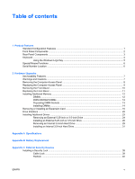
...6 Serial Number Location ...6 2 Hardware Upgrades Serviceability Features ...7 Warnings and Cautions ...7 Removing the Computer Access Panel 8 Replacing the Computer Access Panel 9 Removing the Front Bezel ...10 Replacing the Front Bezel ...11 Installing Additional Memory ...12 DIMMs ...12 DDR2 - HP Dc5750 | Hardware Reference Guide - dc5750 MT - Page 6
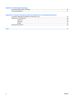
Discharge Preventing Electrostatic Damage ...41 Grounding Methods ...41 Appendix E Computer Operating Guidelines, Routine Care and Shipping Preparation Computer Operating Guidelines and Routine Care 43 Optical Drive Precautions ...44 Operation ...44 Cleaning ...44 Safety ...44 Shipping - HP Dc5750 | Hardware Reference Guide - dc5750 MT - Page 7
The HP Compaq Microtower features may vary depending on the model. For a complete listing of the hardware and software installed in the computer, run the diagnostic utility (included on some computer models only). Instructions for using the utility are provided in the Troubleshooting Guide on - HP Dc5750 | Hardware Reference Guide - dc5750 MT - Page 8
Bus) 2.0 Ports NOTE An optical drive is a CD-ROM , CD-R/RW, DVD-ROM , DVD+R/RW, or CD-RW/DVD Combo drive. The Power On Light is normally green when the power is on. If it is flashing red, there is a problem with the computer and it is displaying a diagnostic code. Refer to the Troubleshooting Guide - HP Dc5750 | Hardware Reference Guide - dc5750 MT - Page 9
and number of connectors may vary by model. The monitor connector on the system board is inactive when a PCI Express graphics card is installed in the computer. The integrated graphics can be enabled if a graphics card based on an ATI graphics controller is plugged into the PCIe x16 slot. If a PCI - HP Dc5750 | Hardware Reference Guide - dc5750 MT - Page 10
Home, Page Up, Delete, End, and Page Down. Indicate the status of the computer and keyboard settings (Num Lock, Caps Lock, and Scroll Lock). Work like a other software applications. Used to open the Start menu in Microsoft Windows. Used in combination with other keys to perform other functions. Used - HP Dc5750 | Hardware Reference Guide - dc5750 MT - Page 11
Logo Key + Tab Displays or hides the Start menu Displays the Desktop Minimizes all open applications Undoes Minimize All Launches My Computer Launches Find Document Launches Find Computer Launches Windows Help Locks the computer if you are connected to a network domain, or allows you to switch - HP Dc5750 | Hardware Reference Guide - dc5750 MT - Page 12
software applications you are using. Serial Number Location Each computer has a unique serial number and product ID number that are located on the top cover of the computer. Keep these numbers available for use when contacting customer service for assistance. Figure 1-2 Serial Number and Product ID - HP Dc5750 | Hardware Reference Guide - dc5750 MT - Page 13
Serviceability Features The computer includes features that make it easy to upgrade and service. No tools are needed for most of the installation procedures described in this chapter. Warnings and Cautions Before performing upgrades be sure to carefully read all of the applicable instructions - HP Dc5750 | Hardware Reference Guide - dc5750 MT - Page 14
2. Remove all removable media, such as diskettes or compact discs, from the computer. 3. Turn off the computer properly through the operating system, then turn off any external devices. 4. Disconnect the power cord from the power outlet and disconnect any external devices. CAUTION Regardless of the - HP Dc5750 | Hardware Reference Guide - dc5750 MT - Page 15
Replacing the Computer Access Panel Place the access panel on the chassis with about 1.3 cm (1/2 inch) of the panel hanging off the the hole for the thumbscrew is aligned with the hole in the chassis and tighten the thumbscrew (2). Figure 2-2 Replacing the Computer Access Panel ENWW Replacing the - HP Dc5750 | Hardware Reference Guide - dc5750 MT - Page 16
2. Remove all removable media, such as diskettes or compact discs, from the computer. 3. Turn off the computer properly through the operating system, then turn off any external devices. 4. Disconnect the power cord from the power outlet and disconnect any external devices. CAUTION Regardless of the - HP Dc5750 | Hardware Reference Guide - dc5750 MT - Page 17
Replacing the Front Bezel Position the chassis in the upright position. Insert the two hooks on the top of the bezel into the rectangular holes on the chassis (1) then rotate the bottom of the bezel onto the chassis (2) so that the bottom two hooks on the bezel snap into place. Figure 2-4 Replacing - HP Dc5750 | Hardware Reference Guide - dc5750 MT - Page 18
achieve the maximum memory support, you can populate the system board with up to 4 GB of memory configured in a highperforming dual channel mode the mandatory JEDEC SPD information In addition, the computer supports: ● 256Mbit, 512Mbit, and 1Gbit non-ECC memory technologies ● single-sided and double- - HP Dc5750 | Hardware Reference Guide - dc5750 MT - Page 19
, 512MB, or 1024MB DIMMs and the system would still operate in dual channel mode. For purposes of "like sizes," a single-sided 512MB DIMM and a double-sided 512MB DIMM would not be the same size because they have different numbers of memory chips on them. ● The system will operate in single channel - HP Dc5750 | Hardware Reference Guide - dc5750 MT - Page 20
DIMMs CAUTION You must disconnect the power cord and wait approximately 30 seconds for the power to drain before adding or removing memory modules. Regardless of the power-on state, voltage is always supplied to the memory modules as long as the computer is plugged into an active AC outlet - HP Dc5750 | Hardware Reference Guide - dc5750 MT - Page 21
steps 7 and 8 to install any additional modules. 10. Replace the computer access panel. 11. Reconnect the power cord and any external devices, then turn on the computer. The computer should automatically recognize the additional memory when you turn on the computer. 12. Lock any security devices - HP Dc5750 | Hardware Reference Guide - dc5750 MT - Page 22
slot. To remove, replace, or add an expansion card: 1. Remove/disengage any security devices that prohibit opening the computer. 2. Remove all removable media, such as diskettes or compact discs, from the computer. 3. Turn off the computer properly through the operating system, then turn off any - HP Dc5750 | Hardware Reference Guide - dc5750 MT - Page 23
expansion socket on the system board and the corresponding expansion slot on the back of the computer chassis. 7. On the rear of the computer, a sliding slot cover lock secures the expansion card brackets and expansion slot covers in place. Loosen the captive thumbscrew that holds the slot cover - HP Dc5750 | Hardware Reference Guide - dc5750 MT - Page 24
expansion card. a. If you are installing an expansion card in a vacant socket, remove the appropriate expansion slot cover on the back of the chassis. Pull the slot cover straight up then away from the inside of the chassis. Figure 2-9 Removing an Expansion Slot Cover 18 Chapter 2 Hardware Upgrades - HP Dc5750 | Hardware Reference Guide - dc5750 MT - Page 25
inside of the chassis (2) to release it from the chassis frame. Be sure not to scrape the card against the other components. Figure 2-10 Removing a Standard PCI Expansion Card c. If your are removing a PCI Express x16 card, pull the retention arm on the back of the expansion socket away from the - HP Dc5750 | Hardware Reference Guide - dc5750 MT - Page 26
. Press the card straight down into the expansion socket on the system board (2). Figure 2-12 Installing an Expansion Card NOTE When installing an expansion card, press firmly on the card so that the whole connector seats properly in the expansion card slot. 20 Chapter 2 Hardware Upgrades ENWW - HP Dc5750 | Hardware Reference Guide - dc5750 MT - Page 27
security devices that were disengaged when the access panel was removed. 17. Reconfigure the computer, if necessary. Refer to the Computer Setup (F10) Utility Guide on the Documentation and Diagnostics CD for instructions about using Computer Setup. ENWW Removing or Installing an Expansion Card 21 - HP Dc5750 | Hardware Reference Guide - dc5750 MT - Page 28
inch internal hard drive bay for optional hard drive To verify the type and size of the storage devices installed in the computer, run Computer Setup. Refer to the Computer Setup (F10) Utility Guide on the Documentation and Diagnostics CD for more information. 22 Chapter 2 Hardware Upgrades ENWW - HP Dc5750 | Hardware Reference Guide - dc5750 MT - Page 29
only. The other four guide screws are black M3 metric screws used for all other drives. CAUTION To prevent loss of work and damage to the computer or drive: If you are inserting or removing a drive, shut down the operating system properly, turn off the computer, and unplug the power cord. Do not - HP Dc5750 | Hardware Reference Guide - dc5750 MT - Page 30
2. Remove all removable media, such as diskettes or compact discs, from the computer. 3. Turn off the computer properly through the operating system, then turn off any external devices. 4. Disconnect the power cord from the power outlet and disconnect any external devices. CAUTION Regardless of the - HP Dc5750 | Hardware Reference Guide - dc5750 MT - Page 31
bracket with release tabs secures the drives in the drive bay. Lift the release tab on the latch drive bracket (1) for the drive you want to remove, then slide the drive from its drive bay (2). Figure 2-17 Removing the External Drives 8. Remove the four guide screws (two on each side) from the - HP Dc5750 | Hardware Reference Guide - dc5750 MT - Page 32
. Make sure to install the appropriate guide screws into the drive. 2. Slide the drive into the drive bay, making sure to align the guide screws with the guide slots, until the drive snaps into place. Figure 2-19 Sliding the External Drives into the Drive Cage 26 Chapter 2 Hardware Upgrades ENWW - HP Dc5750 | Hardware Reference Guide - dc5750 MT - Page 33
an optical drive, connect the power cable (1) and data cable (2) to the back of the drive. Figure 2-20 Connecting the Optical Drive Cables drive, connect the data cable (1) and power cable (2) to the back of the drive. Figure 2-21 Connecting the Diskette Drive Cables 4. If installing a new drive - HP Dc5750 | Hardware Reference Guide - dc5750 MT - Page 34
on the type of drive you plan to install. 7. Replace the front bezel and computer access panel. 8. Reconnect the power cord and any external devices, then turn on the computer. 9. Lock any security devices that were disengaged when the access panel was removed. 28 Chapter 2 Hardware Upgrades ENWW - HP Dc5750 | Hardware Reference Guide - dc5750 MT - Page 35
initially set up the computer to restore the operating system, software drivers, and any software applications that were preinstalled on the computer. If you do not have this CD set, create it now. Refer to the HP Backup and Recovery Manager User Guide in the Windows Start menu for more information - HP Dc5750 | Hardware Reference Guide - dc5750 MT - Page 36
the drive by pulling the green release tab away from the drive (1) and sliding the drive out of the bay (2). Figure 2-25 Removing a Hard Drive 9. Remove the four guide screws (two on each side) from the old drive. You will need these screws to install a new drive. 30 Chapter 2 Hardware Upgrades - HP Dc5750 | Hardware Reference Guide - dc5750 MT - Page 37
3.5-inch Hard Drive NOTE The system does not support Parallel ATA (PATA) hard drives 1. Install the four guide screws (two on each side) that were removed from the old drive into the new drive. The screws help guide the drive into its proper position in the bay. Extra guide screws are provided - HP Dc5750 | Hardware Reference Guide - dc5750 MT - Page 38
set up the computer to restore the operating system, software drivers, and any software applications that were preinstalled on the computer. When the restore process has completed, reinstall any personal files that you backed up before replacing the hard drive. 32 Chapter 2 Hardware Upgrades ENWW - HP Dc5750 | Hardware Reference Guide - dc5750 MT - Page 39
Desktop Dimensions Height Width Depth Approximate Weight Temperature Range Operating Nonoperating Relative Humidity (noncondensing) Operating Nonoperating (38.7°C max wet bulb) Maximum Maximum Typical (idle) Power Supply Operating Voltage Range1 Rated Voltage Range Rated Line Frequency Power - HP Dc5750 | Hardware Reference Guide - dc5750 MT - Page 40
Rated Input Current (maximum)1 8A @ 100 VAC 4A @ 200 VAC 1 This system utilizes a passive power factor corrected power supply. The power factor correction is present in the 230V operating mode only. This allows the system to pass the CE mark requirements for use in the countries of - HP Dc5750 | Hardware Reference Guide - dc5750 MT - Page 41
battery only with the HP spare designated for this product. CAUTION Before replacing the battery, it is important to back up the computer CMOS settings. When the battery is removed or replaced, the CMOS settings will be cleared. Refer to the Computer Setup (F10) Utility Guide on the Documentation - HP Dc5750 | Hardware Reference Guide - dc5750 MT - Page 42
battery holder on the system board. NOTE On some computer models, it may be necessary to remove an internal component to gain access to the battery. 7. Depending on the type of battery holder on the system board, complete the following instructions to replace the battery. Type 1 a. Lift the battery - HP Dc5750 | Hardware Reference Guide - dc5750 MT - Page 43
this procedure. 8. Replace the computer access panel. 9. Plug in the computer and turn on power to the computer. 10. Reset the date and time, your passwords, and any special system setups using Computer Setup. Refer to the Computer Setup (F10) Utility Guide on the Documentation and Diagnostics CD - HP Dc5750 | Hardware Reference Guide - dc5750 MT - Page 44
38 Appendix B Battery Replacement ENWW - HP Dc5750 | Hardware Reference Guide - dc5750 MT - Page 45
information on data security features, refer to the Computer Setup (F10) Utility Guide and the Desktop Management Guide on the Documentation and Diagnostics CD and the HP ProtectTools Security Manager Guide (some models) at http://www.hp.com. Installing a Security Lock The security locks displayed - HP Dc5750 | Hardware Reference Guide - dc5750 MT - Page 46
Padlock Figure C-2 Installing a Padlock 40 Appendix C External Security Devices ENWW - HP Dc5750 | Hardware Reference Guide - dc5750 MT - Page 47
wrist strap connected by a ground cord to a grounded workstation or computer chassis. Wrist straps are flexible straps with a minimum of 1 megohm HP authorized dealer, reseller, or service provider. NOTE For more information on static electricity, contact an HP authorized dealer, reseller, or service - HP Dc5750 | Hardware Reference Guide - dc5750 MT - Page 48
42 Appendix D Electrostatic Discharge ENWW - HP Dc5750 | Hardware Reference Guide - dc5750 MT - Page 49
same operating guidelines listed above will still apply. ● Keep liquids away from the computer and keyboard. ● Never cover the ventilation slots on the monitor with any type of material. ● Install or enable power management functions of the operating system or other software, including sleep states - HP Dc5750 | Hardware Reference Guide - dc5750 MT - Page 50
any object or liquid falls into the drive, immediately unplug the computer and have it checked by an authorized HP service provider. Shipping Preparation Follow these suggestions when preparing to ship the computer: 1. Back up the hard drive files on PD discs, tape cartridges, CDs, or diskettes. Be - HP Dc5750 | Hardware Reference Guide - dc5750 MT - Page 51
locking and unlocking 39 removing 8 replacing 9 audio connectors 2, 3 B backup and recovery 29 battery replacement 35 C computer operating guidelines 43 connecting drive cables 23 D DIMMs. See memory diskette drive installing 26 removing 24 drives connecting cables 23 installing 23 locations 22 DVI - HP Dc5750 | Hardware Reference Guide - dc5750 MT - Page 52
29 optical drive 24 PCI card 19 PCI Express card 19 S security cable lock 39 padlock 40 serial connector 3 serial number location 6 shipping preparation 44 specifications computer 33 memory 12 U unlocking access panel 39 USB ports front panel 2 rear panel 3 V ventilation guidelines 43 W Windows Logo
-
 1
1 -
 2
2 -
 3
3 -
 4
4 -
 5
5 -
 6
6 -
 7
7 -
8
-
9
-
10
-
11
-
12
-
13
-
14
-
15
-
16
-
17
-
18
-
19
-
20
-
21
-
22
-
23
-
24
-
25
-
26
-
27
-
28
-
29
-
30
-
31
-
32
-
33
-
34
-
35
-
36
-
37
-
38
-
39
-
40
-
41
-
42
-
43
-
44
-
45
-
46
-
47
-
48
-
49
-
50
-
51
-
52
 |
 |

Hardware Reference Guide - dc5750
Microtower Model
HP Compaq Business PC