HP Dc7700 Hardware Reference Guide - dc7700 CMT
HP Dc7700 - Compaq Business Desktop Manual
 |
UPC - 882780715318
View all HP Dc7700 manuals
Add to My Manuals
Save this manual to your list of manuals |
HP Dc7700 manual content summary:
- HP Dc7700 | Hardware Reference Guide - dc7700 CMT - Page 1
Hardware Reference Guide - dc7700 Series Convertible Minitower HP Compaq Business PC - HP Dc7700 | Hardware Reference Guide - dc7700 CMT - Page 2
and Windows are trademarks of Microsoft Corporation in the U.S. and other countries. The only warranties for HP products and services are consent of Hewlett-Packard Company. Hardware Reference Guide HP Compaq Business PC dc7700 Series Convertible Minitower First Edition (August 2006) Document part - HP Dc7700 | Hardware Reference Guide - dc7700 CMT - Page 3
About This Book This guide provides basic information for upgrading this computer model. WARNING! Text set off in this manner indicates that failure to follow directions could result in bodily harm or loss of life. CAUTION Text - HP Dc7700 | Hardware Reference Guide - dc7700 CMT - Page 4
iv About This Book ENWW - HP Dc7700 | Hardware Reference Guide - dc7700 CMT - Page 5
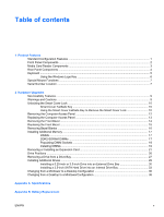
Using the Windows Logo Key 6 Special Mouse Functions ...7 Serial Number Location ...7 2 Hardware Upgrades Serviceability Features ...9 from a Minitower to a Desktop Configuration 36 Changing from a Desktop to a MinitowerConfiguration 38 Appendix A Specifications Appendix B Battery Replacement - HP Dc7700 | Hardware Reference Guide - dc7700 CMT - Page 6
C External Security Devices Installing a Security Lock ...47 Cable Lock ...47 Padlock ...48 Appendix D Electrostatic Discharge Preventing Electrostatic Damage ...49 Grounding Methods ...49 Appendix E Computer Operating Guidelines, Routine Care and Shipping Preparation Computer Operating Guidelines - HP Dc7700 | Hardware Reference Guide - dc7700 CMT - Page 7
the diagnostic utility (included on some computer models only). Instructions for using the utility are provided in the Troubleshooting Guide on the Documentation and Diagnostics CD. NOTE The HP Compaq Convertible Minitower computer can be easily converted to a desktop. For more information, see the - HP Dc7700 | Hardware Reference Guide - dc7700 CMT - Page 8
Button 10 Power On Light 11 USB (Universal Serial Bus) Ports 12 Headphone Connector 13 Microphone Connector NOTE An optical drive is a CD-ROM, DVD+R/RW, or CD-RW/DVD Combo drive. 1 Some models are configured with a media card reader in the external 3.5-inch drive bay. Other models have a bezel - HP Dc7700 | Hardware Reference Guide - dc7700 CMT - Page 9
Components The media card reader is an optional device available on some models only. Refer to the PRO/MS PRO DUO ● Memory Stick (MS) ● MagicGate Memory Stick (MG) ● MagicGate Memory Duo ● Memory Stick Select ● Memory Stick Duo (MS Duo) ● Memory Stick PRO (MS PRO) ● Memory Stick PRO Duo (MS PRO - HP Dc7700 | Hardware Reference Guide - dc7700 CMT - Page 10
in the computer. If a PCI graphics card is installed, the connectors on the card and the system board may be used at the same time. Some settings may need to be changed in Computer Setup to use both connectors. For information about Boot Order, refer to the Computer Setup (F10) Utility Guide on the - HP Dc7700 | Hardware Reference Guide - dc7700 CMT - Page 11
, End, and Page Down. 3 Status Lights Indicate the status of the computer and keyboard settings (Num Lock, Caps Lock, and Scroll Lock). 4 Numeric functions in other software applications. 8 Windows Logo Keys1 Used to open the Start menu in Microsoft Windows. Used in combination with other keys - HP Dc7700 | Hardware Reference Guide - dc7700 CMT - Page 12
Logo Key + Tab Displays or hides the Start menu Displays the Desktop Minimizes all open applications Undoes Minimize All Launches My Computer Launches Find Document Launches Find Computer Launches Windows Help Locks the computer if you are connected to a network domain, or allows you to switch - HP Dc7700 | Hardware Reference Guide - dc7700 CMT - Page 13
applications you are using. Serial Number Location Each computer has a unique serial number and a product ID number that are located on the top cover of the computer. Keep these numbers available for use when contacting customer service for assistance. Figure 1-2 Serial Number and Product ID - HP Dc7700 | Hardware Reference Guide - dc7700 CMT - Page 14
8 Chapter 1 Product Features ENWW - HP Dc7700 | Hardware Reference Guide - dc7700 CMT - Page 15
that make it easy to upgrade and service. No tools are needed for most of the installation procedures described in this chapter. Warnings and Cautions Before performing upgrades be sure to carefully read all of the applicable instructions, cautions, and warnings in this guide. WARNING! To reduce the - HP Dc7700 | Hardware Reference Guide - dc7700 CMT - Page 16
failure ● PC component (for example, processor or power supply) failure ● Forgotten password NOTE The Smart Cover FailSafe Key is a specialized tool available from HP. Be prepared; order this key before you need one. To obtain a FailSafe Key: ● Contact an authorized HP reseller or service provider - HP Dc7700 | Hardware Reference Guide - dc7700 CMT - Page 17
5. Use the Smart Cover FailSafe Key to remove the two tamper-proof screws that secure the Smart Cover Lock to the chassis. Figure 2-1 Removing the Smart Cover Lock Screws 6. Remove the access panel. To reattach the Smart Cover Lock, secure the lock in place with the tamper-proof screws. ENWW - HP Dc7700 | Hardware Reference Guide - dc7700 CMT - Page 18
computer. 3. Turn off the computer properly through the operating system, then turn off any external devices. 4. Disconnect the power cord from the power outlet and disconnect any external devices. CAUTION Regardless of the power Figure 2-2 Removing the Computer Access Panel CAUTION After removing - HP Dc7700 | Hardware Reference Guide - dc7700 CMT - Page 19
Access Panel 1. Lay the computer down on its large base for greater stability. 2. Align the tabs on the access panel with the slots on the chassis and push down on the access panel while sliding it forward until it locks into place. Figure 2-3 Replacing the Computer Access Panel ENWW Replacing the - HP Dc7700 | Hardware Reference Guide - dc7700 CMT - Page 20
computer. 3. Turn off the computer properly through the operating system, then turn off any external devices. 4. Disconnect the power cord from the power outlet and disconnect any external devices. CAUTION Regardless of the power still has power. Turn off the computer and remove the power cord before - HP Dc7700 | Hardware Reference Guide - dc7700 CMT - Page 21
Replacing the Front Bezel 1. Place the bottom hinge points on the front bezel in their corresponding slots in the chassis (1). 2. Rotate the front bezel onto the chassis (2). 3. Snap the catches at the top of the bezel into place (3). 4. Snap the release tabs into place (4). Figure 2-5 Replacing the - HP Dc7700 | Hardware Reference Guide - dc7700 CMT - Page 22
computer. 3. Turn off the computer properly through the operating system, then turn off any external devices. 4. Disconnect the power cord from the power outlet and disconnect any external devices. CAUTION Regardless of the power power. Turn off the computer and remove the power (Desktop Shown - HP Dc7700 | Hardware Reference Guide - dc7700 CMT - Page 23
the mandatory JEDEC SPD information In addition, the computer supports: ● 256Mbit, 512Mbit, and 1Gbit non-ECC memory technologies ● single-sided and double-sided DIMMs ● DIMMs constructed with x8 and x16 DDR devices; DIMMs constructed with x4 SDRAM are not supported NOTE The system will not start if - HP Dc7700 | Hardware Reference Guide - dc7700 CMT - Page 24
memory channel A. Sockets XMM3 and XMM4 operate in memory memory capacity of the DIMMs in Channel A is equal to the total memory capacity of the DIMMs in Channel B. The technology and device of memory describes the total amount of memory that the largest amount of memory is spread between the two - HP Dc7700 | Hardware Reference Guide - dc7700 CMT - Page 25
. If the LED is illuminated, the system still has power. Turn off the computer and remove the power cord before proceeding. The memory module sockets have gold-plated metal contacts. When upgrading the memory, it is important to use memory modules with gold-plated metal contacts to prevent corrosion - HP Dc7700 | Hardware Reference Guide - dc7700 CMT - Page 26
panel. 11. Reconnect the power cord and turn on the computer. 12. Lock any security devices that were disengaged when the computer access panel was removed. The computer should automatically recognize the additional memory the next time you turn on the computer. 20 Chapter 2 Hardware Upgrades ENWW - HP Dc7700 | Hardware Reference Guide - dc7700 CMT - Page 27
media, such as diskettes or compact discs, from the computer. 3. Turn off the computer properly through the operating system, then turn off any external devices. 4. Disconnect the power cord from the power outlet and disconnect any external devices. ENWW Removing or Installing an Expansion Card 21 - HP Dc7700 | Hardware Reference Guide - dc7700 CMT - Page 28
of the DIMM sockets. If the LED is illuminated, the system still has power. Turn off the computer and remove the power cord before proceeding. 6. Locate the correct vacant expansion socket on the system board expansion slot cover or the existing expansion card. 22 Chapter 2 Hardware Upgrades ENWW - HP Dc7700 | Hardware Reference Guide - dc7700 CMT - Page 29
back of the chassis. Lift the expansion slot cover from the expansion slot. Figure 2-11 Removing an Expansion Slot Cover b. If you are removing a standard PCI card, hold the card at each end and carefully rock it back and forth until the connectors pull free from the socket. Lift the card - HP Dc7700 | Hardware Reference Guide - dc7700 CMT - Page 30
it. Be sure not to scrape the card against other components. Figure 2-13 Removing a PCI Express x16 Expansion Card 9. Store the removed card in anti-static packaging. 10. If you are not installing a new expansion card, install an expansion slot cover to close the open slot. CAUTION After removing - HP Dc7700 | Hardware Reference Guide - dc7700 CMT - Page 31
a new expansion power cord and turn on the computer. 16. Lock any security devices that were disengaged when the computer access panel was removed. 17. Reconfigure the computer, if necessary. Refer to the Computer Setup (F10) Utility Guide on the Documentation and Diagnostics CD for instructions - HP Dc7700 | Hardware Reference Guide - dc7700 CMT - Page 32
Desktop and Minitower bays is available from HP. 2 Depending on the computer configuration, you may have devices installed in the computer, run Computer Setup. Refer to the Computer Setup (F10) Utility Guide on the Documentation and Diagnostics CD for more information. 26 Chapter 2 Hardware Upgrades - HP Dc7700 | Hardware Reference Guide - dc7700 CMT - Page 33
or compact discs, from the computer. 3. Turn off the computer properly through the operating system, then turn off any external devices. 4. Disconnect the power cord from the power outlet and disconnect any external devices. CAUTION Regardless of the power-on state, voltage is always present - HP Dc7700 | Hardware Reference Guide - dc7700 CMT - Page 34
drivelock mechanism (1) for that specific drive and slide the drive from the drive bay (2). Figure 2-17 Removing a 3.5-inch Drive or a 5.25-inch Drive in the Minitower Configuration (Optical Drive shown) 9. Store the removed drive in anti-static packaging. 28 Chapter 2 Hardware Upgrades ENWW - HP Dc7700 | Hardware Reference Guide - dc7700 CMT - Page 35
metric screws are black. The HP-supplied standard screws are silver. CAUTION To prevent loss of work and damage to the computer or drive: If you are inserting or removing a drive, shut down the operating system properly, turn off the computer, and unplug the power cord. Do not remove a drive - HP Dc7700 | Hardware Reference Guide - dc7700 CMT - Page 36
drive may be an optical drive (CD-ROM, CD-R/RW, DVD-ROM, DVD+R/RW, or CD-RW/DVD Combo drive) or a media card reader with a 5.25-inch adapter kit attached. 1. Remove/disengage any security devices that prohibit opening the computer. 2. Remove all removable media, such as diskettes or compact discs - HP Dc7700 | Hardware Reference Guide - dc7700 CMT - Page 37
guide screws. Eight extra metric guide screws are provided on the diskette drive bracket under the access panel. The HP-supplied metric screws are black. Figure 2-19 Installing a 5.25-Inch Drive in a Minitower (top) and Desktop bay supports a power connectors. ENWW Installing Additional Drives 31 - HP Dc7700 | Hardware Reference Guide - dc7700 CMT - Page 38
any security devices that were disengaged when the computer access panel was removed. 15. Reconfigure the computer, if necessary. Refer to the Computer Setup (F10) Utility Guide on the Documentation and Diagnostics CD for instructions about using Computer Setup. 32 Chapter 2 Hardware Upgrades ENWW - HP Dc7700 | Hardware Reference Guide - dc7700 CMT - Page 39
initially set up the computer to restore the operating system, software drivers, and any software applications that were preinstalled on the computer. If you do not have this CD set, create it now. Refer to the HP Backup and Recovery Manager User Guide in the Windows Start menu for more information - HP Dc7700 | Hardware Reference Guide - dc7700 CMT - Page 40
guide screws line up with the guide slots in the drive cage. The use of unnecessary force when installing any drive into the drive bay may result in damage to the drive. 8. Connect the power cable (1) and data cable (2) to the rear of the hard drive. Figure 2-23 Connecting the Power problems. - HP Dc7700 | Hardware Reference Guide - dc7700 CMT - Page 41
Reconnect the power cord and turn on the computer. 12. Lock any security devices that were disengaged when the computer access panel was removed. 13. Reconfigure the computer, if necessary. Refer to the Computer Setup (F10) Utility Guide on the Documentation and Diagnostics CD for instructions about - HP Dc7700 | Hardware Reference Guide - dc7700 CMT - Page 42
a Minitower to a Desktop Configuration 1. Remove/disengage any security devices that prohibit opening the computer. 2. Remove all removable media, such as diskettes or compact discs, from the computer. 3. Turn off the computer properly through the operating system, then turn off any external devices - HP Dc7700 | Hardware Reference Guide - dc7700 CMT - Page 43
depth than the upper two bays. The bottom bay supports a drive that is no more than 17 cm to the drive. 11. Reconnect all power and data cables to the drives in Minitower to a Desktop Configuration 15. Replace the front bezel and computer access panel. ENWW Changing from a Minitower to a Desktop - HP Dc7700 | Hardware Reference Guide - dc7700 CMT - Page 44
16. Reconnect the power cord and turn on the computer. 17. Lock any security devices that were disengaged when the computer access panel was removed. Changing from a Desktop to a MinitowerConfiguration 1. Remove/disengage any security devices that prohibit opening the computer. 2. Remove all - HP Dc7700 | Hardware Reference Guide - dc7700 CMT - Page 45
a shorter depth than the upper two bays. The bottom bay supports a drive that is no more than 17 cm (6.7 inches) result in damage to the drive. 11. Reconnect all power and data cables to the drives in the 5.25- minitower configuration. ENWW Changing from a Desktop to a MinitowerConfiguration 39 - HP Dc7700 | Hardware Reference Guide - dc7700 CMT - Page 46
2-29 Changing from a Desktop to a Minitower Configuration 15. Replace the front bezel and computer access panel. 16. Reconnect the power cord and turn on the computer. 17. Lock any security devices that were disengaged when the computer access panel was removed. 40 Chapter 2 Hardware Upgrades ENWW - HP Dc7700 | Hardware Reference Guide - dc7700 CMT - Page 47
if the computer is equipped with a 17.8 in port security bracket) Approximate Weight 35 lb Weight Supported (maximum distributed load for Desktop 100 lb configuration installed. Heat Dissipation Maximum Typical (idle) Power Supply 1,916 BTU/hr 375 BTU/hr 115V 483 kg-cal/hr 95 kg-cal/hr - HP Dc7700 | Hardware Reference Guide - dc7700 CMT - Page 48
factor corrected power supply. This allows the system to pass the CE mark requirements for use in the countries of the European Union. The active power factor corrected power supply also has the added benefit of not requiring an input voltage range select switch. 42 Appendix A Specifications ENWW - HP Dc7700 | Hardware Reference Guide - dc7700 CMT - Page 49
to AC power. HP encourages customers to recycle used electronic hardware, HP original print cartridges, and rechargeable batteries. For more information about recycling programs, go to http://www.hp.com/ recycle. 1. Remove/disengage any security devices that prohibit opening the computer. 2. Remove - HP Dc7700 | Hardware Reference Guide - dc7700 CMT - Page 50
the DIMM sockets. If the LED is illuminated, the system still has power. Turn off the computer and remove the power cord before proceeding. 6. Locate the battery and battery holder on the system board. NOTE On some computer models, it may be necessary to remove an internal component to gain access - HP Dc7700 | Hardware Reference Guide - dc7700 CMT - Page 51
9. Plug in the computer and turn on power to the computer. 10. Reset the date and time, your passwords, and any special system setups using Computer Setup. Refer to the Computer Setup (F10) Utility Guide on the Documentation and Diagnostics CD. 11. Lock any security devices that were disengaged when - HP Dc7700 | Hardware Reference Guide - dc7700 CMT - Page 52
46 Appendix B Battery Replacement ENWW - HP Dc7700 | Hardware Reference Guide - dc7700 CMT - Page 53
C External Security Devices NOTE For information on data security features, refer to the Computer Setup (F10) Utility Guide and the Desktop Management Guide on the Documentation and Diagnostics CD and the HP ProtectTools Security Manager Guide (some models) at http://www.hp.com. Installing a - HP Dc7700 | Hardware Reference Guide - dc7700 CMT - Page 54
Padlock Figure C-2 Installing a Padlock 48 Appendix C External Security Devices ENWW - HP Dc7700 | Hardware Reference Guide - dc7700 CMT - Page 55
devices. This type of damage may reduce the life expectancy of the device to a grounded workstation or computer chassis. Wrist straps are flexible HP authorized dealer, reseller, or service provider. NOTE For more information on static electricity, contact an HP authorized dealer, reseller, or service - HP Dc7700 | Hardware Reference Guide - dc7700 CMT - Page 56
50 Appendix D Electrostatic Discharge ENWW - HP Dc7700 | Hardware Reference Guide - dc7700 CMT - Page 57
with the keyboard feet down, directly against the front of the desktop unit as this also restricts airflow. ● Never operate the computer with the cover or side panel removed. ● Do not stack computers on top of each other or place computers so near each other that they are subject to each other's re - HP Dc7700 | Hardware Reference Guide - dc7700 CMT - Page 58
or plan to store data. 4. Turn off the computer and external devices. 5. Disconnect the power cord from the electrical outlet, then from the computer. 6. Disconnect the system components and external devices from their power sources, then from the computer. NOTE Ensure that all boards are seated - HP Dc7700 | Hardware Reference Guide - dc7700 CMT - Page 59
35 battery replacement 43 F FailSafe Key 10 front bezel removing 14 removing blanks 16 replacing 15 front panel components 2 G guide screws 29 C changing computer configuration 36, 38 computer operating guidelines 51 connecting drive cables 29 D desktop conversion 36 DIMMs. See memory diskette - HP Dc7700 | Hardware Reference Guide - dc7700 CMT - Page 60
bezel 14 media card reader 27 PCI card 23 PCI Express card 24 Smart Cover Lock 10 S security cable lock 47 padlock 48 Smart Cover Lock 10 serial connector 4 serial number location 7 shipping preparation 52 Smart Cover Lock 10 specifications computer 41 memory 17 U unlocking access panel USB ports
-
 1
1 -
 2
2 -
 3
3 -
 4
4 -
 5
5 -
 6
6 -
 7
7 -
8
-
9
-
10
-
11
-
12
-
13
-
14
-
15
-
16
-
17
-
18
-
19
-
20
-
21
-
22
-
23
-
24
-
25
-
26
-
27
-
28
-
29
-
30
-
31
-
32
-
33
-
34
-
35
-
36
-
37
-
38
-
39
-
40
-
41
-
42
-
43
-
44
-
45
-
46
-
47
-
48
-
49
-
50
-
51
-
52
-
53
-
54
-
55
-
56
-
57
-
58
-
59
-
60
 |
 |

Hardware Reference Guide - dc7700 Series
Convertible Minitower
HP Compaq Business PC