HP Designjet 4000 Service Manual - Page 262
When connecting the Vacuum Fan, After installing the NEW Vacuum
 |
View all HP Designjet 4000 manuals
Add to My Manuals
Save this manual to your list of manuals |
Page 262 highlights
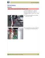
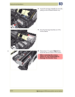
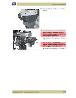
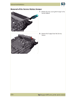
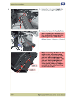
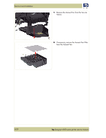
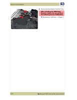
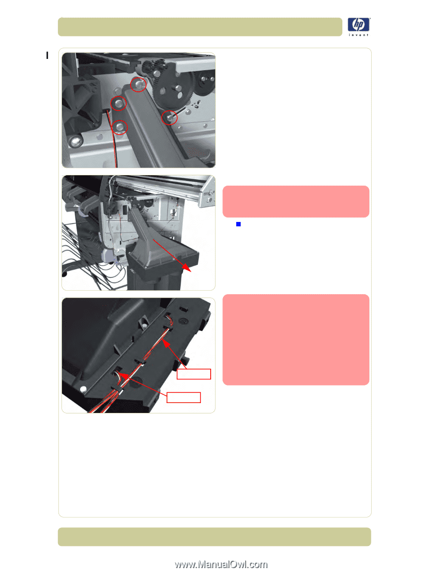
Removal and Installation 7. Remove four T-20 screws (Type B) that secure the Vacuum Fan to the Printer. 8. Remove the Vacuum Fan from the Printer. After installing the NEW Vacuum Fan, make sure you perform the following Service Calibration: „ Paper Advance Calibration ⇒ Chapter 5. Cable 2 Cable 1 When connecting the Vacuum Fan cables to the Interconnect PCA, make sure you connect the cable with the label marked Vacuum Fan 1 to connector 1 and the cable with the label marked Vacuum Fan 2 to connector 2. You can verify if both cables are labelled correctly by the actual markings on the Vacuum Fan. 8-28 hp designjet 4000 series printer service manual
-
 1
1 -
2
-
3
-
4
-
5
-
6
-
7
-
8
-
9
-
10
-
11
-
12
-
13
-
14
-
15
-
16
-
17
-
18
-
19
-
20
-
21
-
22
-
23
-
24
-
25
-
26
-
27
-
28
-
29
-
30
-
31
-
32
-
33
-
34
-
35
-
36
-
37
-
38
-
39
-
40
-
41
-
42
-
43
-
44
-
45
-
46
-
47
-
48
-
49
-
50
-
51
-
52
-
53
-
54
-
55
-
56
-
57
-
58
-
59
-
60
-
61
-
62
-
63
-
64
-
65
-
66
-
67
-
68
-
69
-
70
-
71
-
72
-
73
-
74
-
75
-
76
-
77
-
78
-
79
-
80
-
81
-
82
-
83
-
84
-
85
-
86
-
87
-
88
-
89
-
90
-
91
-
92
-
93
-
94
-
95
-
96
-
97
-
98
-
99
-
100
-
101
-
102
-
103
-
104
-
105
-
106
-
107
-
108
-
109
-
110
-
111
-
112
-
113
-
114
-
115
-
116
-
117
-
118
-
119
-
120
-
121
-
122
-
123
-
124
-
125
-
126
-
127
-
128
-
129
-
130
-
131
-
132
-
133
-
134
-
135
-
136
-
137
-
138
-
139
-
140
-
141
-
142
-
143
-
144
-
145
-
146
-
147
-
148
-
149
-
150
-
151
-
152
-
153
-
154
-
155
-
156
-
157
-
158
-
159
-
160
-
161
-
162
-
163
-
164
-
165
-
166
-
167
-
168
-
169
-
170
-
171
-
172
-
173
-
174
-
175
-
176
-
177
-
178
-
179
-
180
-
181
-
182
-
183
-
184
-
185
-
186
-
187
-
188
-
189
-
190
-
191
-
192
-
193
-
194
-
195
-
196
-
197
-
198
-
199
-
200
-
201
-
202
-
203
-
204
-
205
-
206
-
207
-
208
-
209
-
210
-
211
-
212
-
213
-
214
-
215
-
216
-
217
-
218
-
219
-
220
-
221
-
222
-
223
-
224
-
225
-
226
-
227
-
228
-
229
-
230
-
231
-
232
-
233
-
234
-
235
-
236
-
237
-
238
-
239
-
240
-
241
-
242
-
243
-
244
-
245
-
246
-
247
-
248
-
249
-
250
-
251
-
252
-
253
-
254
-
255
-
256
-
 257
257 -
 258
258 -
 259
259 -
 260
260 -
 261
261 -
 262
262 -
 263
263 -
 264
264 -
 265
265 -
 266
266 -
 267
267 -
268
-
269
-
270
-
271
-
272
-
273
-
274
-
275
-
276
-
277
-
278
-
279
-
280
-
281
-
282
-
283
-
284
-
285
-
286
-
287
-
288
-
289
-
290
-
291
-
292
-
293
-
294
-
295
-
296
-
297
-
298
-
299
-
300
-
301
-
302
-
303
-
304
-
305
-
306
-
307
-
308
-
309
-
310
-
311
-
312
-
313
-
314
-
315
-
316
-
317
-
318
-
319
-
320
-
321
-
322
-
323
-
324
-
325
-
326
-
327
-
328
-
329
-
330
-
331
-
332
-
333
-
334
-
335
-
336
-
337
-
338
-
339
-
340
-
341
-
342
-
343
-
344
-
345
-
346
-
347
-
348
-
349
-
350
-
351
-
352
-
353
-
354
-
355
-
356
-
357
-
358
-
359
-
360
-
361
-
362
-
363
-
364
-
365
-
366
-
367
-
368
-
369
-
370
-
371
-
372
 |
 |
8-28
Removal and Installation
hp
designjet 4000 series printer service manual
7.
Remove four T-20 screws (
Type B
) that
secure the Vacuum Fan to the Printer.
8.
Remove the Vacuum Fan from the Printer.
After installing the NEW Vacuum
Fan, make sure you perform the
following Service Calibration:
Paper Advance Calibration
⇒
Chapter 5.
When connecting the Vacuum Fan
cables to the Interconnect PCA,
make sure you connect the cable
with the label marked Vacuum
Fan 1 to connector 1 and the cable
with the label marked Vacuum
Fan 2 to connector 2. You can
verify if both cables are labelled
correctly by the actual markings
on the Vacuum Fan.
Cable 2
Cable 1