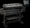
HP Designjet 815mfp HP Designjet 815mfp - Assembly and Maintenance Poster
HP Designjet 815mfp Manual
 |
View all HP Designjet 815mfp manuals
Add to My Manuals
Save this manual to your list of manuals |
HP Designjet 815mfp manual content summary:
- HP Designjet 815mfp | HP Designjet 815mfp - Assembly and Maintenance Poster - Page 1
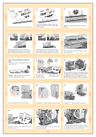
kit 7 assembly kit 8 power cables 9 cross bar 10 bottom bar 11 USB and FireWire cable 12 feet (x2) 13 scanner maintenance sheet 14 touch screen arm 15 keyboard 16 touch screen hub 17 touch screen 18 FireWire cable 19 media guides (×2) 20 system recovery CD-ROM assembly poster Your printer - HP Designjet 815mfp | HP Designjet 815mfp - Assembly and Maintenance Poster - Page 2
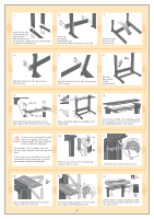
wire guide to the two legs using four M6×30 and two M6×10 screws. Remove using the same parts, just 'mirror' the assembly procedure described here. 10 Attach the touch screen arm to the stand legs using two M6×12 screws. 11 Attach the brace using two M4×6 screws. 12 13 14 hp designjet copier - HP Designjet 815mfp | HP Designjet 815mfp - Assembly and Maintenance Poster - Page 3
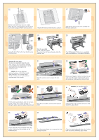
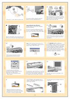
printer's feet will be positioned outside the scanner's feet. Your HP Designjet 815mfp is now assembled and should appear as in the above illustration. cleaning the scan area... You are now required to clean the scan area. To do so, you will need the cleaning tools provided in the maintenance kit - HP Designjet 815mfp | HP Designjet 815mfp - Assembly and Maintenance Poster - Page 4
, close the scanner cover. keep out dust and reduce maintenance 35 36 time... Cover your scanner with the plastic dust cover when not in use. Caution: make sure the scanner power is off when using the dust cover. Connect the touch screen to the scanner using the FireWire cable, fastening - HP Designjet 815mfp | HP Designjet 815mfp - Assembly and Maintenance Poster - Page 5
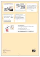
51 Your HP Designjet comes equipped with two Insert the plastic caps in the holes on the touch magnetic media guides; these can be placed screen arm. and moved as required. When the maintenance procedure has completed, remove the scanner maintenance sheet and return it to its protective cover - HP Designjet 815mfp | HP Designjet 815mfp - Assembly and Maintenance Poster - Page 6
kit 7 assembly kit 8 power cables 9 cross bar 10 bottom bar 11 USB and FireWire cable 12 feet (x2) 13 scanner maintenance sheet 14 touch screen arm 15 keyboard 16 touch screen hub 17 touch screen 18 FireWire cable 19 media guides (×2) 20 system recovery CD-ROM assembly poster Your printer
-
 1
1 -
 2
2 -
 3
3 -
 4
4 -
 5
5 -
 6
6
 |
 |

system recovery
cd-rom
hp
designjet copier cc800ps
Your printer
should already be
assembled and working before starting this
procedure. For instructions on how to
assemble the printer, please refer to the
assembly poster included with the printer.
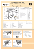
read these instructions carefully...
and complete each stage before you start the
next.
what you will need to do the job
Because some of the components of your
HP Designjet 815mfp are bulky, you will need
2 or 3 people
to lift them. See the
descriptions that follow for details, a symbol
like this is used:
a note about fixings
When initially assembling your
HP Designjet 815mfp stand do not fully tighten
the screws; you will be asked to do this later.
assembly poster
touch screen
assembly
touch screen
assembly
2
4
5
12
13
14
11
8
16
15
20
10
7
assembly kit contents
description
quantity
screw M6×10 for base and top bar and arm
12
Allen T key 5 mm for touch screen arm
1
power cable clips
17
wire routing clips
5
brace
1
plastic caps
4
screw M6×30 for base and top bar
8
Allen key 2.5 mm for touch screen arm brace
1
screw M4×8 for touch screen and key board assembly hub
7
special screw for scanner
4
screw M3x8 for touch screen assembly hub
1
Allen key 2 mm for keyboard assembly
1
6
1
9
19
hp
designjet 815mfp
assembly instructions and
routine maintenance procedures
plastic dust cover
3
1
scanner
2
rear table
3
top bar with guide
4
leg (×2)
5
maintenance kit
6
assembly kit
7
power cables
8
cross bar
9
bottom bar
10
USB and FireWire cable
11
media guides (×2)
19
system recovery CD-ROM
20
feet (x2)
12
scanner maintenance sheet
13
touch screen arm
14
keyboard
15
touch screen hub
16
touch screen
17
FireWire cable
18
17
18
please note
The touch screen assembly can be mounted on
either the right or the left side of the stand.
please note
The touch screen assembly can be mounted on
either the right or the left side of the stand.
1