HP Disk Carrier Blade for bh3710 Site Preparation Guide, Second Edition - HP C
HP Disk Carrier Blade for bh3710 Manual
 |
View all HP Disk Carrier Blade for bh3710 manuals
Add to My Manuals
Save this manual to your list of manuals |
HP Disk Carrier Blade for bh3710 manual content summary:
- HP Disk Carrier Blade for bh3710 | Site Preparation Guide, Second Edition - HP C - Page 1
hp Carrier Grade Blade Server bh3710 Site Preparation Guide Edition 2.0 Manufacturing Part Number: bh3710_SitePrep July 2002 U.S.A. © Copyright 2002-2004 Hewlett-Packard Development Company, L.P.. - HP Disk Carrier Blade for bh3710 | Site Preparation Guide, Second Edition - HP C - Page 2
2002-2004 Hewlett-Packard Development Company, L.P. Audience Assumptions This guide is for the person who installs, administers, and troubleshoots LAN servers. Hewlett-Packard Company assumes you are qualified in the servicing of computer equipment and trained in recognizing hazards in products - HP Disk Carrier Blade for bh3710 | Site Preparation Guide, Second Edition - HP C - Page 3
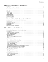
Contents 1. HP Carrier Grade Blade Server bh3710 Overview Introduction 7 Site Preparation Guide Contents 7 Front View 8 Rear View 9 Air Flow 10 Blade Server 10 Power Supply 11 System Backplane 12 DC Power Supplies 12 bp2200 Server Blade 16 - HP Disk Carrier Blade for bh3710 | Site Preparation Guide, Second Edition - HP C - Page 4
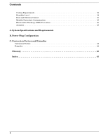
Contents Cooling Requirements 32 Humidity Level 34 Dust and Pollution Control 35 Metallic Particulate Contamination 35 Electrostatic Discharge (ESD) Prevention 36 Acoustics 36 A. System Specifications and Requirements B. Power Plug Configuration C. Conversion Factors and Formulas Conversion - HP Disk Carrier Blade for bh3710 | Site Preparation Guide, Second Edition - HP C - Page 5
Figures Figure 1-1. Blade Server Front View 8 Figure 1-2. Blade Server Rear View 9 Figure 1-3. Blade Server Cooling Airflow (Front View 10 Figure 1-4. Power Supply Cooling Fan Location 11 Figure 1-5. Blade Server Backplane, rear view 12 Figure 1-6. Blade Server Backplane, front view 12 Figure - HP Disk Carrier Blade for bh3710 | Site Preparation Guide, Second Edition - HP C - Page 6
Figures 6 - HP Disk Carrier Blade for bh3710 | Site Preparation Guide, Second Edition - HP C - Page 7
either stand alone or mounts in a standard 19-inch, two column EIA rack. Site Preparation Guide Contents Before preparing your site for an HP Carrier Grade Blade Server bh3710, familiarize yourself with the . • Glossary-provides a glossary of terms most commonly used in this manual. Chapter 1 7 - HP Disk Carrier Blade for bh3710 | Site Preparation Guide, Second Edition - HP C - Page 8
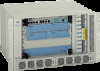
Front View Front View The components available at the front of this 6 EIA unit high (6U) server are: • Ten individual Compact PCI slots supporting defined configurations for 1-slot and 2-slot PCAs • Vertical cooling fan tray with slot status LEDs on the bulkhead • Two hot swap n+1 power supplies - HP Disk Carrier Blade for bh3710 | Site Preparation Guide, Second Edition - HP C - Page 9
View The components available at the rear of this 6 EIA unit high (6U) server are: • Two hot swap N+1 inlet modules • 10 individual Compact PCI slots supporting defined configurations for blades Figure 1-2 Blade Server Rear View Chapter 1 9 - HP Disk Carrier Blade for bh3710 | Site Preparation Guide, Second Edition - HP C - Page 10
HP Carrier Grade Blade Server bh3710 Overview Air Flow Air Flow Blade Server The Blade Server utilizes a right-side front to left side back cooling scheme. Six fans integrated on a vertical tray cool the system. Refer to Appendix A for System Specifications. Air enters the vent along the right - HP Disk Carrier Blade for bh3710 | Site Preparation Guide, Second Edition - HP C - Page 11
HP Carrier Grade Blade Server bh3710 Overview Air Flow Power Supply Each power supply contains cooling fans. Cool air flows through each power supply from front to back. Because they are separated by the solid bottom of the card cage, power supply air and blade server air do not mix. Figure 1-4 - HP Disk Carrier Blade for bh3710 | Site Preparation Guide, Second Edition - HP C - Page 12
HP Carrier Grade Blade Server bh3710 Overview System Backplane System Backplane The passive system backplane is located in the Blade Server to accommodate front and rear blades. Ten Compact PCI slots are located on each side. Figure 1-5 Blade Server Backplane, rear view Figure 1-6 Blade Server - HP Disk Carrier Blade for bh3710 | Site Preparation Guide, Second Edition - HP C - Page 13
HP Carrier Grade Blade Server bh3710 Overview DC Power Supplies Both modules reside in the lower bay of the chassis. They are accessed from both the front and rear of the chassis as illustrated in Figure 1-7 and Figure 1-8. Each power supply has two visible LEDs that display operating conditions: • - HP Disk Carrier Blade for bh3710 | Site Preparation Guide, Second Edition - HP C - Page 14
HP Carrier Grade Blade Server bh3710 Overview DC Power Supplies • A yellow LED illuminates whenever the power supply is in a fault condition. Figure 1-7 HP Blade Server DC Power Inlet Module (rear view) 14 Chapter 1 - HP Disk Carrier Blade for bh3710 | Site Preparation Guide, Second Edition - HP C - Page 15
Figure 1-8 HP Carrier Grade Blade Server bh3710 Overview DC Power Supplies HP Blade Server DC Power Supply (front view) Chapter 1 15 - HP Disk Carrier Blade for bh3710 | Site Preparation Guide, Second Edition - HP C - Page 16
HP Carrier Grade Blade Server bh3710 Overview bp2200 Server Blade bp2200 Server Blade The Blade Server contains one bp2200 server blade that comes factory installed and is pre-configured with HP-UX. The bp2200 server blade is double-wide and resides in slots 1 and 2. A label matches the blade to - HP Disk Carrier Blade for bh3710 | Site Preparation Guide, Second Edition - HP C - Page 17
HP Carrier Grade Blade Server bh3710 Overview Installing Optional Fibre Channel (FC) Disk Carriers Installing Optional Fibre Channel (FC) Disk Carriers Additional storage capacity for server blades can be added using the FC disk carrier with one or two additional drives installed. The carrier and - HP Disk Carrier Blade for bh3710 | Site Preparation Guide, Second Edition - HP C - Page 18
HP Carrier Grade Blade Server bh3710 Overview Fan Assemblies The two systems are separate and do not provide cooling for each other. See figure below for airflow information. Figure 1-13 Cooling Air Flow Cooling Fan Airflow (out) PS Airflow (out) PS Airflow (in) Cooling Fan Airflow (in) 18 - HP Disk Carrier Blade for bh3710 | Site Preparation Guide, Second Edition - HP C - Page 19
HP Carrier Grade Blade Server bh3710 Overview Server Blade Fan Tray Server Blade Fan Tray The Server Blade Fan Tray is a single unit located in a vertical housing on the right side of the Blade Server front. The Tray must be removed and replaced within 20 seconds to keep the system from shutting - HP Disk Carrier Blade for bh3710 | Site Preparation Guide, Second Edition - HP C - Page 20
HP Carrier Grade Blade Server bh3710 Overview Power Supply Fans Power Supply Fans Power Supply Fans are integral to the power supply and can only be changed by removing and replacing the power supply. Figure 1-15 Power Supply Fans Power Supply Cooling Fans Slot Blockers Any slot that is not - HP Disk Carrier Blade for bh3710 | Site Preparation Guide, Second Edition - HP C - Page 21
HP Carrier Grade Blade Server bh3710 Overview Blade Server Racking Information Blade Server Racking Information The racking kit enables the installation of the bh3710 chassis into a rack. Rack kit installation documentation is shipped with each server inside the rack kit box. Racking information may - HP Disk Carrier Blade for bh3710 | Site Preparation Guide, Second Edition - HP C - Page 22
HP Carrier Grade Blade Server bh3710 Overview Blade Server Racking Information 22 Chapter 1 - HP Disk Carrier Blade for bh3710 | Site Preparation Guide, Second Edition - HP C - Page 23
and preparing the site. Careful site planning and preparation ensures trouble-free installation and reliable operation of HP Blade Servers. to the Blade Server. NOTE Electrical practices and suggestions in this guide are based on North American practices. For countries outside North America - HP Disk Carrier Blade for bh3710 | Site Preparation Guide, Second Edition - HP C - Page 24
, affect the quality of electrical power. Common sources of these fluctuations are: • Fluctuations occurring within the facility's distribution system • Utility service low-voltage conditions (such as sags or brownouts) • Wide and rapid variations in input power frequency • Electrical storms • Large - HP Disk Carrier Blade for bh3710 | Site Preparation Guide, Second Edition - HP C - Page 25
system design to provide immunity to power outages of less than one cycle. However, testing cannot conclusively rule out loss of service. Therefore, adherence to the following guidelines provides the best possible performance of power distribution systems for HP server equipment: • Dedicated power - HP Disk Carrier Blade for bh3710 | Site Preparation Guide, Second Edition - HP C - Page 26
that these parts be solidly interconnected to provide an equipotential ground to all points. Main Building Electrical Ground The main electrical service entrance equipment should have an earth ground connection, as required by applicable codes. Connections such as a grounding rod, building steel, or - HP Disk Carrier Blade for bh3710 | Site Preparation Guide, Second Edition - HP C - Page 27
equal potential over a broad band of frequencies. The grounding grid should be connected to the equipment cabinet and electrical service entrance ground at multiple connection points using a minimum #6 AWG (16mm2) wire ground conductor. Figure 2-1 illustrates a metallic strip grounding system - HP Disk Carrier Blade for bh3710 | Site Preparation Guide, Second Edition - HP C - Page 28
designed as a ground grid with bolted down stringers and corrosion resistive plating (to provide low resistance and attachment points for connection to service entrance ground and HP server equipment). The use of conductive floor tiles with this style of grid further enhances ground performance. The - HP Disk Carrier Blade for bh3710 | Site Preparation Guide, Second Edition - HP C - Page 29
Hewlett-Packard equipment. Refer to the appropriate installation guide for installation procedures. Wiring Connections Expansion and contraction loose or too tight can have a high impedance that cause serious problems, such as erratic equipment operation. A high impedance connection overheats and - HP Disk Carrier Blade for bh3710 | Site Preparation Guide, Second Edition - HP C - Page 30
General System and Facility Guidelines Environmental Factors Environmental Factors The environmental factors discussed in this section are: • "Computer Room Preparation" • "Space Requirements" • "Floor Loading" • "Cooling Requirements" • "Humidity Level" • "Dust and Pollution Control" • "Metallic - HP Disk Carrier Blade for bh3710 | Site Preparation Guide, Second Edition - HP C - Page 31
be provided for proper cooling airflow through the equipment. The service area space requirements, outlined in Appendix A, are minimum dimensions. Equipment cable routing Floor Loading The computer room floor must be able to support the total weight of the installed computer system as well as the - HP Disk Carrier Blade for bh3710 | Site Preparation Guide, Second Edition - HP C - Page 32
or install any equipment cabinets on the raised floor system until you have carefully examined it to verify that it is adequate to support the appropriate installation. Floor Loading Terms The table below defines floor-loading terms: Table 2-1 Floor Loading Term Definitions Term Dead load Live - HP Disk Carrier Blade for bh3710 | Site Preparation Guide, Second Edition - HP C - Page 33
General System and Facility Guidelines Environmental Factors Basic Air Conditioning Equipment Requirement The cooling capacity of the installed air conditioning equipment for the computer room should be sufficient to offset the computer equipment dissipation loads, as well as any space envelope heat - HP Disk Carrier Blade for bh3710 | Site Preparation Guide, Second Edition - HP C - Page 34
General System and Facility Guidelines Environmental Factors An air distribution system should be zoned to deliver an adequate amount of supply air to the cooling air intake vents of the computer system equipment cabinets. Supply air temperature should be maintained within the following parameters: - HP Disk Carrier Blade for bh3710 | Site Preparation Guide, Second Edition - HP C - Page 35
levels of electrostatic charges. This increases the electrostatic discharge (ESD) voltage potential. ESD can cause component damage during servicing operations. Paper feed problems on high-speed printers are usually encountered in low-humidity environments. Low humidity levels are often the result - HP Disk Carrier Blade for bh3710 | Site Preparation Guide, Second Edition - HP C - Page 36
concern has developed in computer rooms where these conductive contaminants are formed on the bottom of some raised floor tiles. Although this problem is relatively rare, it may be an issue within your computer room. Since metallic contamination can cause permanent or intermittent failures on - HP Disk Carrier Blade for bh3710 | Site Preparation Guide, Second Edition - HP C - Page 37
A System Specifications and Requirements Table A-1 System Specifications Description Specification Dimensions (H, W, D) 10.5 x 17 x 14 in (26.25 x 42.50 x 35.00 cm) Weight (configured) approximately 51 lbs (23.4 Kg) Input Power Operational: -40 to -70 VDC (Margin included) Recommended: -48 to - HP Disk Carrier Blade for bh3710 | Site Preparation Guide, Second Edition - HP C - Page 38
System Specifications and Requirements Table A-2 Power Consumption (Maximum) (Continued) Power Required VAa Power Supply 750.0 Watts a. These wattage values are used to perform the calculations in Table A-3, "Power Consumption and Air Conditioning Requirement Summary." Table A-3 Power - HP Disk Carrier Blade for bh3710 | Site Preparation Guide, Second Edition - HP C - Page 39
B Power Plug Configuration The power cable designed for the DC Blade Server is shown below. Figure B-1 bh3710 DC Power Plug The end of the power cable where the male plug goes will be unterminated. Appendix B 39 - HP Disk Carrier Blade for bh3710 | Site Preparation Guide, Second Edition - HP C - Page 40
Power Plug Configuration 40 Appendix B - HP Disk Carrier Blade for bh3710 | Site Preparation Guide, Second Edition - HP C - Page 41
and formulas will assist in data calculation for systems that do not conform specifically to the configurations listed in this Site Preparation Guide. Conversion factors used in this document and additional conversion factors that may be helpful in determining factors required for site preparation - HP Disk Carrier Blade for bh3710 | Site Preparation Guide, Second Edition - HP C - Page 42
Conversion Factors and Formulas Formulas Formulas KVA =Voltage x Current (amps) Watts =VA x PF BTU =Watts x 3.41 42 Appendix C - HP Disk Carrier Blade for bh3710 | Site Preparation Guide, Second Edition - HP C - Page 43
excessive heat or blocking the natural airflow, and connecting wires or cables. The FCC (Federal Communications Commission) regulates a portion of this problem through Part 15 of their rules and regulations. Even more stringent than the FCC Part 15 requirements, Network Equipment Building Standards - HP Disk Carrier Blade for bh3710 | Site Preparation Guide, Second Edition - HP C - Page 44
Glossary PCI PCI Currently, the most popular local I/O bus, the Peripheral Component Interconnect (PCI) bus was developed by Intel and introduced in 1993. power consumption that a customer will most likely experience and can use for power budgeting purposes. PICMG A consortium of companies - HP Disk Carrier Blade for bh3710 | Site Preparation Guide, Second Edition - HP C - Page 45
control, 35 E EIA unit, 43 electrical conduits, 25 connection, 29 load requirements, 24 electrical metallic tubing (EMT), 25 electrical service, main building, 26 electromagnetic interference (EMI), 29, 43 electrostatic discharge (ESD), 29, 36, 43 environmental factors, 30 F fan assemblies - HP Disk Carrier Blade for bh3710 | Site Preparation Guide, Second Edition - HP C - Page 46
Index O online uninterruptible power supply (UPS), 25 overview, 7 P peripheral component interconnect (PCI), 44 power consumption, 37 panel, 26 quality, 24 supply, 11, 12 supply fans, 20 system protection, 24 power factor, definition, 44 power plug configuration, 39 power supply labeling, 37 printed
-
 1
1 -
 2
2 -
 3
3 -
 4
4 -
 5
5 -
 6
6 -
 7
7 -
8
-
9
-
10
-
11
-
12
-
13
-
14
-
15
-
16
-
17
-
18
-
19
-
20
-
21
-
22
-
23
-
24
-
25
-
26
-
27
-
28
-
29
-
30
-
31
-
32
-
33
-
34
-
35
-
36
-
37
-
38
-
39
-
40
-
41
-
42
-
43
-
44
-
45
-
46
 |
 |

hp Carrier Grade Blade Server bh3710 Site
Preparation Guide
Edition 2.0
Manufacturing Part Number: bh3710_SitePrep
July 2002
U.S.A.
© Copyright 2002-2004 Hewlett-Packard Development Company, L.P..