HP Dl180 ProLiant DL180 Generation 5 Server Installation Sheet
HP Dl180 - G6 E5504 2X2gb 4Lff Svr Manual
 |
UPC - 883585990917
View all HP Dl180 manuals
Add to My Manuals
Save this manual to your list of manuals |
HP Dl180 manual content summary:
- HP Dl180 | ProLiant DL180 Generation 5 Server Installation Sheet - Page 1
2007) Part number 458198-001 Important Safety Information Item Description 1 Two front USB 2.0 ports 2 Optical drive 3 Optical drive activity indicator 4 Optical drive eject button 5 Optical drive manual eject hole 6 UID LED Button 7 System Health LED 8 NIC 1 LED 9 NIC 2 LED 10 - HP Dl180 | ProLiant DL180 Generation 5 Server Installation Sheet - Page 2
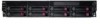
the top cover Server Configuration Overview The steps listed below give an overview of the necessary setup procedures for preparing the HP ProLiant DL180 G5 Server for operation: 1. Unpack the server and rack mounting hardware. 2. Install other options, such as additional memory, hard drives, or - HP Dl180 | ProLiant DL180 Generation 5 Server Installation Sheet - Page 3
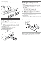
latch inward until it clicks. Figure 6 Installing the hard drive assembly Installing a Memory Module The following guidelines must be followed when memory modules are being added or replaced: • For 2P system, both physical processors must be of the same type and speed. • 533/667 MHz Registered ECC - HP Dl180 | ProLiant DL180 Generation 5 Server Installation Sheet - Page 4
a Processor The HP ProLiant DL180 G5 server supports Dual-Core Intel® Xeon® 5100 Series processors and Quad-Core Intel® Xeon® 5300 Series processors. To install the processor: 1. Insert the processor into the socket, using the key on the processor. 2. Engage the retention plate and the load
-
 1
1 -
 2
2 -
 3
3 -
 4
4
 |
 |

HP ProLiant DL180
Generation 5 Server
Installation Sheet
First edition (November 2007)
Part number 458198-001
Important Safety Information
Les "Viktig sikkerhetsinformasjon" på dokumentasjons-CDen før du installerer dette produktet.
Læs dokumentet Vigtige sikkerhedsoplysninger på dokumentations-cd'en, før produktet installeres.
Prima dell'installazione, leggere sul CD le Informazioni importanti sulla sicurezza.
Tärkeisiin turvatietoihin" Documentation CD -levyllä ennen tuotteen asentamista.
Läs dokumentet Viktig säkerhetsinformation på dokumentations-cd:n innan du installerar denna produkt.
Identifying Server Components
Front Panel Components
Figure 1
Front panel components of servers with 8 HDDs
Item
Description
1
Two front USB 2.0 ports
2
Optical drive
3
Optical drive activity indicator
4
Optical drive eject button
5
Optical drive manual eject hole
6
UID LED Button
7
System Health LED
8
NIC 1 LED
9
NIC 2 LED
10
Power button
11
Thumbscrews for the front bezel
12
Optional HDD
13
Online LED
14
Fault/UID LED
15
Hard disk drive (HDD) bay
Figure 2
Front panel components of servers with 12 HDDs
Item
Description
1
Two front USB 2.0 ports
2
UID LED button
3
System Health LED
4
NIC 1 LED
5
NIC 2 LED
6
Power button
7
Thumbscrews for the front bezel
8
Online LED
9
Fault/UID LED
10
Hard disk drive (HDD) bay
11
Optional HDD