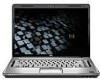
HP Dv5-1160us HP Pavilion dv5 Entertainment PC - Maintenance and Service Guide
HP Dv5-1160us - Pavilion Entertainment - Core 2 Duo GHz Manual
 |
UPC - 884420430155
View all HP Dv5-1160us manuals
Add to My Manuals
Save this manual to your list of manuals |
HP Dv5-1160us manual content summary:
- HP Dv5-1160us | HP Pavilion dv5 Entertainment PC - Maintenance and Service Guide - Page 1
HP Pavilion dv5 Entertainment PC Maintenance and Service Guide - HP Dv5-1160us | HP Pavilion dv5 Entertainment PC - Maintenance and Service Guide - Page 2
. Bluetooth is a trademark owned by its proprietor and used by Hewlett-Packard Company services. Nothing herein should be construed as constituting an additional warranty. HP shall not be liable for technical or editorial errors or omissions contained herein. First Edition: August 2008 Document Part - HP Dv5-1160us | HP Pavilion dv5 Entertainment PC - Maintenance and Service Guide - Page 3
, such as an adjoining optional printer, or a soft surface, such as pillows or rugs or clothing, to block airflow. Also, do not allow the AC adapter to contact the skin or a soft surface, such as pillows or rugs or clothing, during operation. The computer and the AC - HP Dv5-1160us | HP Pavilion dv5 Entertainment PC - Maintenance and Service Guide - Page 4
iv Safety warning notice - HP Dv5-1160us | HP Pavilion dv5 Entertainment PC - Maintenance and Service Guide - Page 5
Left-side components ...15 Bottom components ...16 3 Illustrated parts catalog Service tag ...17 Computer parts ...34 Sequential part number listing ...35 4 Removal and replacement procedures Preliminary replacement requirements 44 Tools required ...44 Service considerations ...44 Plastic parts - HP Dv5-1160us | HP Pavilion dv5 Entertainment PC - Maintenance and Service Guide - Page 6
47 Equipment guidelines 48 Unknown user password 49 Component replacement procedures 50 Service tag ...50 Computer feet ...51 Battery ...52 Webcam/microphone module 53 Optical drive ...55 TV tuner module ...57 RTC battery ...59 Memory module ...60 Hard drive ...62 WLAN module ...65 Switch - HP Dv5-1160us | HP Pavilion dv5 Entertainment PC - Maintenance and Service Guide - Page 7
System Configuration menu 107 Diagnostics menu ...108 6 Specifications Computer specifications ...109 15.4-inch, SXGA+ display specifications 110 15.4-inch WXGA display specifications 111 Hard drive specifications ...112 Blu-ray Disc ROM Drive with SuperMulti DVD±R/RW Double-Layer 113 DVD±RW and - HP Dv5-1160us | HP Pavilion dv5 Entertainment PC - Maintenance and Service Guide - Page 8
External monitor ...148 HDMI ...149 RJ-11 (modem) ...150 RJ-45 (network) ...150 Universal Serial Bus ...151 10 Power cord set requirements Requirements for all countries or regions 152 Requirements for specific countries or regions 153 11 Recycling Battery ...154 Display ...154 Index ...160 viii - HP Dv5-1160us | HP Pavilion dv5 Entertainment PC - Maintenance and Service Guide - Page 9
Computer models equipped with AMD processors and graphics subsystems with UMA memory Computer models equipped with Intel processors and graphics subsystems with discrete memory HP Pavilion dv5 Entertainment PC √ √ √ AMD processors: AMD Turion™ Ultra Dual-Core 35W √ √ ZM-86 2.40-GHz with - HP Dv5-1160us | HP Pavilion dv5 Entertainment PC - Maintenance and Service Guide - Page 10
models equipped with 1024 MB ● Memory size is dynamic change Discrete graphics subsystem memory √ ● GeForce 9650M GT, Nvidia NB9PGS with 512 MB (32 MB × 16 DDR2 ×8 PCs) ● GeForce 9300M GS, Nvidia NB9MGEB with 256 MB (32 MB × 16 DDR2 × 4 PCs) ● 15.4-inch, WSXGA+ (1680 × 1050) √ √ √ AntiGlare - HP Dv5-1160us | HP Pavilion dv5 Entertainment PC - Maintenance and Service Guide - Page 11
Intel processors and graphics subsystems with discrete memory Supports up to 4096 MB system memory √ √ √ ● 4096-MB total system memory (2048 MB × 2, dual-channel) ● 3072-MB total system memory (2048 MB × 1 + 1024 × 1) ● 2048-MB total system memory (1024 MB × 2, dual-channel) ● 2048-MB total - HP Dv5-1160us | HP Pavilion dv5 Entertainment PC - Maintenance and Service Guide - Page 12
memory Computer models equipped with Intel processors and graphics subsystems with discrete memory Fixed (1 screw for removal) √ √ √ Support for Supports Microsoft Premium √ √ √ Requirements Pavilion-branded Altec Lansing √ √ √ speakers 56K V.92 data/fax modem √ √ √ Supports - HP Dv5-1160us | HP Pavilion dv5 Entertainment PC - Maintenance and Service Guide - Page 13
) TV tuner antenna (select models only) √ √ USB (4 on computer models not √ √ √ equipped with an eSATA port; 3 on computer models equipped with an eSATA port) VGA (Dsub 15-pin) √ √ √ 2-pin AC power for 90-W AC adapter √ √ √ Expansion port 3 supports the HP √ √ √ xb3000 Notebook - HP Dv5-1160us | HP Pavilion dv5 Entertainment PC - Maintenance and Service Guide - Page 14
Windows Vista Premium (32 bit) √ √ √ Windows Vista Ultimate (64 bit) √ √ √ Serviceability AC adapter √ √ √ Battery (system) √ √ √ Hard drives (2) √ √ √ Memory module √ √ √ Optical drive √ √ √ TV tuner module √ √ √ WLAN module √ √ √ 6 Chapter 1 Product description - HP Dv5-1160us | HP Pavilion dv5 Entertainment PC - Maintenance and Service Guide - Page 15
models only) Description Turns off the display and initiates Sleep if the display is closed while the power is on. Send and receive signals from one or more wireless devices. These antennae are not visible to your country or region. These notices are located in Help and Support. Top components 7 - HP Dv5-1160us | HP Pavilion dv5 Entertainment PC - Maintenance and Service Guide - Page 16
Item (3) (4) (5) Component Internal microphones (2) Integrated webcam light Integrated webcam Description Record sound. On: The integrated webcam is in use. Records video and captures still photographs. 8 Chapter 2 External component identification - HP Dv5-1160us | HP Pavilion dv5 Entertainment PC - Maintenance and Service Guide - Page 17
button for at least 5 seconds to turn off the computer. To learn more about your power settings, select Start > Control Panel > System and Maintenance > Power Options. ● Launches the QuickPlay program (for models with QuickPlay preinstalled). NOTE: If the computer has been set up to require a logon - HP Dv5-1160us | HP Pavilion dv5 Entertainment PC - Maintenance and Service Guide - Page 18
reader Allows a fingerprint logon to Windows, instead of a password logon. *This table describes factory settings. For information about changing factory settings, refer to the user guides located in Help and Support. 10 Chapter 2 External component identification - HP Dv5-1160us | HP Pavilion dv5 Entertainment PC - Maintenance and Service Guide - Page 19
Keys Item (1) (2) Component esc key fn key (3) Windows logo key (4) Windows applications key (5) Embedded numeric keypad keys (6) Function keys Function Displays system information about your computer when pressed in combination with the fn key. Executes frequently used system functions - HP Dv5-1160us | HP Pavilion dv5 Entertainment PC - Maintenance and Service Guide - Page 20
TouchPad light ● White: TouchPad is enabled. ● Amber: TouchPad is disabled. (2) TouchPad* Moves the pointer and selects or activates items on the screen. (3) TouchPad left button* Functions like the left button on an external mouse. (4) TouchPad on/off button Enables/disables the TouchPad - HP Dv5-1160us | HP Pavilion dv5 Entertainment PC - Maintenance and Service Guide - Page 21
jacks (2) Produce sound when connected to optional powered stereo speakers, headphones, ear buds, a headset, or television audio. NOTE: This table describes factory settings. For information about changing factory settings, refer to the user guides located in Help and Support. Front components 13 - HP Dv5-1160us | HP Pavilion dv5 Entertainment PC - Maintenance and Service Guide - Page 22
-side components Item (1) (2) (3) (4) Component Optical drive light Optical drive USB ports (2) TV antenna jack (select models only) (5) RJ-11 (modem) jack (select models only) (6) Security cable slot (7) Power connector Function Blinking: The optical drive is being accessed. Reads optical - HP Dv5-1160us | HP Pavilion dv5 Entertainment PC - Maintenance and Service Guide - Page 23
IEEE 1394 or 1394a device, such as a camcorder. On: A digital card is being accessed. Supports the following optional digital card formats: Secure Digital (SD) Memory Card, MultiMediaCard (MMC), Memory Stick (MS), Memory Stick Pro (MSP), xD-Picture Card (XD), xD-Picture Card (XD) Type H, xD-Picture - HP Dv5-1160us | HP Pavilion dv5 Entertainment PC - Maintenance and Service Guide - Page 24
. Holds the battery. Releases the battery from the battery bay. Contains the memory module slots. Holds the TV tuner card and, for select models only, the Intel Turbo Memory card. Holds the hard drive and the WLAN module. CAUTION: To prevent an unresponsive system, replace the wireless module - HP Dv5-1160us | HP Pavilion dv5 Entertainment PC - Maintenance and Service Guide - Page 25
number (p/n): This number provides specific information about the product's hardware components. The part number helps a service technician to determine what components and parts are needed. (4) Model description: This is the number needed to locate documents, drivers, and support for the computer - HP Dv5-1160us | HP Pavilion dv5 Entertainment PC - Maintenance and Service Guide - Page 26
15.4-inch display assemblies (include wireless antenna transceivers and cables) WSXGA+ AntiGlare display assembly with webcam and 2 microphones WSXGA+ BrightView display assembly with webcam and 2 microphones WXGA AntiGlare display assembly with webcam and 2 microphones Spare part number - HP Dv5-1160us | HP Pavilion dv5 Entertainment PC - Maintenance and Service Guide - Page 27
information on display assembly spare part numbers. Switch cover (includes LED board and cable) 488316-001 Power button board (includes cable) 486796 United States 488590-001 Speaker assembly 486801-001 Bluetooth® modules (do not include a Bluetooth module cable) For use only with computer - HP Dv5-1160us | HP Pavilion dv5 Entertainment PC - Maintenance and Service Guide - Page 28
(9d) (10) (11) (12) (13) (14) (15) Description Spare part number Bluetooth module cable 489822-001 Cable Kit, includes: 501891-001 NOTE: See Cable Kit on page 31 for more Cable Kit spare part information. Power connector cable Modem module cable TV tuner module antenna cable Plastics Kit - HP Dv5-1160us | HP Pavilion dv5 Entertainment PC - Maintenance and Service Guide - Page 29
part replacement thermal material): For use only with computer models equipped with AMD processors and graphics subsystems with discrete memory memory 492314-001 Base enclosures (include rubber feet) For use only with computer models equipped with a 1394 port, modem module, and 486783-001 TV tuner - HP Dv5-1160us | HP Pavilion dv5 Entertainment PC - Maintenance and Service Guide - Page 30
483863-001 RTC battery 491571-001 TV tuner modules: NOTE: The TV tuner module spare part kits do not include a TV tuner module cable. The TV tuner module cable is included in the Cable Kit, spare part number 501891-001. DVB-T TV tuner module 482899-003 DVB-T/ANG TV tuner module 482899-002 - HP Dv5-1160us | HP Pavilion dv5 Entertainment PC - Maintenance and Service Guide - Page 31
Item (23) Description Spare part number 512-MB memory module for use only with computer models equipped with Intel processors 484266-001 WLAN modules: WLAN modules for use only with computer models equipped with - HP Dv5-1160us | HP Pavilion dv5 Entertainment PC - Maintenance and Service Guide - Page 32
Item Description Spare part number Namibia, Nauru, Nepal, the Nether Antilles, the Netherlands, New Zealand, Nicaragua, Niger, Nigeria, Norway, Oman, Pakistan, , Brazil, the British Virgin Islands, Brunei, 482957-001 480985-001 487330-001 487330-002 24 Chapter 3 Illustrated parts catalog - HP Dv5-1160us | HP Pavilion dv5 Entertainment PC - Maintenance and Service Guide - Page 33
Item (24) Description Spare part number Bulgaria, Burkina Faso, Burundi, Cameroon, Cape Verde, the Central African Republic, Chad, Chile, the People's Republic of China, Colombia, Comoros, the Congo, Costa Rica, - HP Dv5-1160us | HP Pavilion dv5 Entertainment PC - Maintenance and Service Guide - Page 34
Item Description Spare part number Hard drives for use only with computer models equipped with AMD processors: ● 320-GB, 5400-rpm ● 250-GB, 5400-rpm left and right bracket rails, connector 483862-001 cable, Mylar cover with tab, and 4 rubber isolators) 26 Chapter 3 Illustrated parts catalog - HP Dv5-1160us | HP Pavilion dv5 Entertainment PC - Maintenance and Service Guide - Page 35
assembly components The HP Pavilion dv5 Entertainment PC offers 2 types of display assemblies. Component spare parts are listed in this section for AntiGlare display assemblies and BrightView display assemblies. AntiGlare display assembly spare parts Item (1) (2) (3) (4) (5) Description Display - HP Dv5-1160us | HP Pavilion dv5 Entertainment PC - Maintenance and Service Guide - Page 36
BrightView display assembly spare parts Item (1) (2) (3) (4) (5) Description Spare part number Display bezel (includes logo and display lid switch actuator magnet) 480444-001 Webcam/ only with computer models equipped with WXGA display panels 493020-001 28 Chapter 3 Illustrated parts catalog - HP Dv5-1160us | HP Pavilion dv5 Entertainment PC - Maintenance and Service Guide - Page 37
Item (6) (7) (8) Description Spare part number Wireless antenna transceivers and cables: For use with computer models equipped with 802.11a/b/g/n WLAN modules (includes 489804-001 3 wireless antenna transceivers and cables) - HP Dv5-1160us | HP Pavilion dv5 Entertainment PC - Maintenance and Service Guide - Page 38
Plastics Kit Item (1) (2) (3) (4) Description Spare part number Plastics Kit 486793-001 ExpressCard slot bezel Mini Card module compartment cover (includes 1 captive screw, secured by a C-clip) Memory module compartment cover (includes 1 captive screw, secured by a C-clip) Hard drive bay - HP Dv5-1160us | HP Pavilion dv5 Entertainment PC - Maintenance and Service Guide - Page 39
Cable Kit Item (1) (2) (3) (4) Description Cable Kit Bluetooth module cable Power connector cable Modem module cable (includes RJ-11 jack) TV tuner module cable Spare part number 501891-001 Cable Kit 31 - HP Dv5-1160us | HP Pavilion dv5 Entertainment PC - Maintenance and Service Guide - Page 40
Mass storage devices Item (1) (2) Description Spare part number Hard drives (include left and right bracket rails, connector cable, Mylar cover with tab, and 4 rubber ROM Drive with SuperMulti DVD±R/RW Double-Layer, LightScribe, and 486525-002 bronze bezel 32 Chapter 3 Illustrated parts catalog - HP Dv5-1160us | HP Pavilion dv5 Entertainment PC - Maintenance and Service Guide - Page 41
Item Description Spare part number Blu-ray Disc ROM Drive with SuperMulti DVD±R/RW Double-Layer, LightScribe, and 486525-001 silver bezel DVD±RW and CD-RW SuperMulti Double- - HP Dv5-1160us | HP Pavilion dv5 Entertainment PC - Maintenance and Service Guide - Page 42
Miscellaneous parts Description Spare part number AC adapters 90-W AC adapter 391173-001 and 463955-001 65-W AC adapter Carrying cases HP carrying case 463958-001 418162-001 HP slim bag CAT5E cable Wired headset with volume control Optical mouse 418163-001 454619-001 371693-003 436238-001 - HP Dv5-1160us | HP Pavilion dv5 Entertainment PC - Maintenance and Service Guide - Page 43
with volume control 90-W AC adapter Bluetooth module for use only with computer models equipped with AMD processors (does not include a Bluetooth module cable) NOTE: The Bluetooth module cable is available using spare part number 489822-001. HP carrying case HP slim bag carrying case Wireless laser - HP Dv5-1160us | HP Pavilion dv5 Entertainment PC - Maintenance and Service Guide - Page 44
Spare part number 454619-001 459263-001 459263-002 459339-001 459339-002 Description Singapore, Slovakia, Slovenia, the Solomon Islands Arab Emirates, the United Kingdom, Uruguay, Uzbekistan, Vanuatu, Venezuela, Vietnam, Yemen, Zaire, Zambia, and Zimbabwe 36 Chapter 3 Illustrated parts catalog - HP Dv5-1160us | HP Pavilion dv5 Entertainment PC - Maintenance and Service Guide - Page 45
isolators) 90-W AC adapter 65-W AC adapter Full-function remote control replacement thermal material) System board with RS780 Northbridge and ATI-M UMA graphics subsystem memory for use only with computer models equipped with AMD processors (includes replacement thermal material) Sequential part - HP Dv5-1160us | HP Pavilion dv5 Entertainment PC - Maintenance and Service Guide - Page 46
NB9P-GS discrete graphics subsystem memory for use only with computer models equipped with Intel processors (includes replacement thermal material) NTSC/ATSC/ANG TV tuner module NOTE: The TV tuner module spare part kits do not include a TV tuner module cable. The TV tuner module cable is included in - HP Dv5-1160us | HP Pavilion dv5 Entertainment PC - Maintenance and Service Guide - Page 47
55-Wh, 2.55-Ah Li-ion battery for use with all computer models 6-cell, 47-Wh, 2.55-Ah Li-ion battery for use only with computer models equipped replacement thermal material) AMD Athlon X2 Dual-Core 35W QL-60 1.90-GHz with 1-MB L2 cache processor (includes replacement thermal material) 512-MB memory - HP Dv5-1160us | HP Pavilion dv5 Entertainment PC - Maintenance and Service Guide - Page 48
with computer models equipped with a 1394 port, modem module, and TV tuner module (includes rubber feet) Base enclosure for use only with computer models for more Cable Kit spare part information. Rubber Feet Kit (includes 4 base enclosure rubber feet) Screw Kit Power button board (includes cable - HP Dv5-1160us | HP Pavilion dv5 Entertainment PC - Maintenance and Service Guide - Page 49
only with computer models equipped with Intel processors and graphics subsystems with discrete memory (includes replacement thermal material) Speaker assembly Broadcom 4322 802.11a/b/g/n WLAN module for use only use in Latin America Keyboard for use in Saudi Arabia Sequential part number listing 41 - HP Dv5-1160us | HP Pavilion dv5 Entertainment PC - Maintenance and Service Guide - Page 50
and 4 rubber isolators) Bluetooth module cable Power cord for use in Canada, French Canada, Power cord for use in the United Kingdom and Hong Kong Power cord for use in Italy Power cord for use in Denmark Power cord for use in Switzerland Power cord for use in Brazil 42 Chapter 3 Illustrated parts - HP Dv5-1160us | HP Pavilion dv5 Entertainment PC - Maintenance and Service Guide - Page 51
for use in South Africa Power cord for use in Israel Power cord for use in Argentina Power cord for use in India RTC battery Fan/heat sink assembly for use only with computer models equipped with AMD processors and graphics subsystems with UMA memory (includes replacement thermal material) Fan/heat - HP Dv5-1160us | HP Pavilion dv5 Entertainment PC - Maintenance and Service Guide - Page 52
area to prevent damage. Plastic parts CAUTION: Using excessive force during disassembly and reassembly can damage plastic parts. Use care when handling the plastic parts. Apply pressure only at the points designated in the maintenance instructions. 44 Chapter 4 Removal and replacement procedures - HP Dv5-1160us | HP Pavilion dv5 Entertainment PC - Maintenance and Service Guide - Page 53
Cables and connectors CAUTION: When servicing the computer, be sure that cables are placed in that cables are routed in such a way that they cannot be caught or snagged by parts being removed or replaced. Handle flex cables with extreme care; these cables tear easily. Drive handling CAUTION: Drives - HP Dv5-1160us | HP Pavilion dv5 Entertainment PC - Maintenance and Service Guide - Page 54
many cases, ESD contains enough power to alter device parameters or in the internal layers, reducing its life expectancy. CAUTION: To prevent damage in foam-lined box Typical electrostatic voltage levels Relative humidity 10% 40% 35,000 V 15,000 V 12,000 V 5,000 V 6,000 V 800 V 2,000 V 700 - HP Dv5-1160us | HP Pavilion dv5 Entertainment PC - Maintenance and Service Guide - Page 55
components, parts, and assemblies by the case or PCM laminate. Handle these items only at static-free workstations. ● Avoid contact with pins, leads, or circuitry. ● Turn off power and input signals before inserting or removing connectors or test equipment. Preliminary replacement requirements 47 - HP Dv5-1160us | HP Pavilion dv5 Entertainment PC - Maintenance and Service Guide - Page 56
resistance ● Static-dissipative tables or floor mats with hard ties to the ground ● Field service kits ● Static awareness labels ● Material-handling packages ● Nonconductive plastic bags, tubes, or Voltage protection level 1,500 V 7,500 V 5,000 V 48 Chapter 4 Removal and replacement procedures - HP Dv5-1160us | HP Pavilion dv5 Entertainment PC - Maintenance and Service Guide - Page 57
AC outlet and then unplugging the AC adapter from the computer. 4. Remove the battery (see Battery on page 52). 5. Remove the RTC battery (see RTC battery on page 59). 6. Wait approximately 5 minutes. 7. Replace the RTC battery and reassemble the computer. 8. Connect AC power to the computer. Do not - HP Dv5-1160us | HP Pavilion dv5 Entertainment PC - Maintenance and Service Guide - Page 58
number (p/n): This number provides specific information about the product's hardware components. The part number helps a service technician to determine what components and parts are needed. (4) Model description: This is the number needed to locate documents, drivers, and support for the computer - HP Dv5-1160us | HP Pavilion dv5 Entertainment PC - Maintenance and Service Guide - Page 59
Computer feet The computer feet are adhesive-backed rubber pads. The feet are included in the Rubber Feet Kit, spare part number 486794-001. There are 4 rubber feet that attach to the base enclosure in the locations illustrated below. Component replacement procedures 51 - HP Dv5-1160us | HP Pavilion dv5 Entertainment PC - Maintenance and Service Guide - Page 60
. 2. Disconnect all external devices connected to the computer. 3. Disconnect the power from the computer by first unplugging the power cord from the AC outlet and then unplugging the AC adapter from the computer. Remove the battery: 1. Turn the computer upside down on a flat surface. 2. Slide the - HP Dv5-1160us | HP Pavilion dv5 Entertainment PC - Maintenance and Service Guide - Page 61
all external devices connected to the computer. 3. Disconnect the power from the computer by first unplugging the power cord from the AC outlet and then unplugging the AC adapter from the computer. 4. Remove the battery (see Battery on page 52). Remove the webcam/microphone module: 1. Turn - HP Dv5-1160us | HP Pavilion dv5 Entertainment PC - Maintenance and Service Guide - Page 62
module cable (2) from the webcam/microphone module. 7. Remove the webcam/microphone module. Reverse this procedure to install the webcam/microphone module. 54 Chapter 4 Removal and replacement procedures - HP Dv5-1160us | HP Pavilion dv5 Entertainment PC - Maintenance and Service Guide - Page 63
bezel and bracket. Description Spare part number Blu-ray Disc ROM Drive power from the computer by first unplugging the power cord from the AC outlet and then unplugging the AC adapter from the computer. 4. Remove the battery (see Battery the optical drive.) Component replacement procedures 55 - HP Dv5-1160us | HP Pavilion dv5 Entertainment PC - Maintenance and Service Guide - Page 64
4. Use the disc tray frame to slide the optical drive (3) out of the computer. 5. Remove the optical drive. 6. If it is necessary to replace the optical drive bracket, position the optical drive with the optical drive bracket toward you. 7. Remove the two Phillips PM2.0×4.0 screws (1) that secure - HP Dv5-1160us | HP Pavilion dv5 Entertainment PC - Maintenance and Service Guide - Page 65
devices connected to the computer. 3. Disconnect the power from the computer by first unplugging the power cord from the AC outlet and then unplugging the AC Adapter from the computer. 4. Remove the battery (see Battery on page 52). Remove the TV tuner module: 1. Position the computer with the front - HP Dv5-1160us | HP Pavilion dv5 Entertainment PC - Maintenance and Service Guide - Page 66
the TV tuner module (3) by pulling the module away from the slot at an angle. NOTE: The TV tuner module is designed with a notch (4) to prevent incorrect insertion into the TV tuner module slot. Reverse this procedure to install the TV tuner module. 58 Chapter 4 Removal and replacement procedures - HP Dv5-1160us | HP Pavilion dv5 Entertainment PC - Maintenance and Service Guide - Page 67
first unplugging the power cord from the AC outlet and then unplugging the AC adapter from the computer. 4. Remove the battery (see Battery on page 52). 5. Remove the Mini Card module compartment cover (see TV tuner module on page 57). Remove the RTC battery: Remove the RTC battery from the socket - HP Dv5-1160us | HP Pavilion dv5 Entertainment PC - Maintenance and Service Guide - Page 68
devices connected to the computer. 3. Disconnect the power from the computer by first unplugging the power cord from the AC outlet and then unplugging the AC adapter from the computer. 4. Remove the battery (see Battery on page 52). Remove the memory module: 1. Position the computer with the front - HP Dv5-1160us | HP Pavilion dv5 Entertainment PC - Maintenance and Service Guide - Page 69
5. Remove the module (2) by pulling it away from the slot at an angle. NOTE: Memory modules are designed with a notch (3) to prevent incorrect insertion into the memory module slot. Reverse this procedure to install a memory module. Component replacement procedures 61 - HP Dv5-1160us | HP Pavilion dv5 Entertainment PC - Maintenance and Service Guide - Page 70
cover with tab, and 4 rubber isolators. Description Spare part number Hard drives for use only with computer models equipped with power from the computer by first unplugging the power cord from the AC outlet and then unplugging the AC adapter from the computer. 4. Remove the battery (see Battery - HP Dv5-1160us | HP Pavilion dv5 Entertainment PC - Maintenance and Service Guide - Page 71
bay cover (2), swing it up and to the left, and remove the cover (3). The hard drive bay cover is included in the Plastics Kit, spare part number 486793-001. 4. Use the Mylar tab (1) to slide the hard drive to the left (2), and then lift it to release it from the hard - HP Dv5-1160us | HP Pavilion dv5 Entertainment PC - Maintenance and Service Guide - Page 72
7. If it is necessary to replace the hard drive bracket or any of the hard drive bracket components, remove the following: (1) Four Phillips PM3 isolators (5) Hard drive connector cable Reverse this procedure to reassemble and install the hard drive. 64 Chapter 4 Removal and replacement procedures - HP Dv5-1160us | HP Pavilion dv5 Entertainment PC - Maintenance and Service Guide - Page 73
WLAN module Description Spare part number For use only with computer models equipped with AMD processors: Atheros AR9280 802.11a Arab Emirates, the United Kingdom, Uruguay, Uzbekistan, Vanuatu, Venezuela, Vietnam, Yemen, Zaire, Zambia, and Zimbabwe 453730-002 Component replacement procedures 65 - HP Dv5-1160us | HP Pavilion dv5 Entertainment PC - Maintenance and Service Guide - Page 74
Description Spare part number Atheros AR2425 802.11b/g for use only with computer models equipped with AMD processors in 459339-001 , Sweden, Switzerland, Taiwan, Tajikistan, Tanzania, Togo, Tonga, Trinidad and Tobago, Tunisia, Turkey, 487330-002 66 Chapter 4 Removal and replacement procedures - HP Dv5-1160us | HP Pavilion dv5 Entertainment PC - Maintenance and Service Guide - Page 75
Spare part number power from the computer by first unplugging the power cord from the AC outlet and then unplugging the AC adapter from the computer. 4. Remove the battery (see Battery on page 52). 5. Remove the hard drive (see Hard drive on page 62). Remove the WLAN module: Component replacement - HP Dv5-1160us | HP Pavilion dv5 Entertainment PC - Maintenance and Service Guide - Page 76
regulates wireless devices in your country or region. If you replace the module and then receive a warning message, remove the module to restore computer functionality, and then contact technical support through Help and Support. 1. Disconnect the WLAN antenna cables (1) from the WLAN module. NOTE - HP Dv5-1160us | HP Pavilion dv5 Entertainment PC - Maintenance and Service Guide - Page 77
part power from the computer by first unplugging the power cord from the AC outlet and then unplugging the AC adapter from the computer. 4. Remove the battery (see Battery on page 52). Remove the switch cover and keyboard: 1. Position the computer with the front toward you. Component replacement - HP Dv5-1160us | HP Pavilion dv5 Entertainment PC - Maintenance and Service Guide - Page 78
of the switch cover (1) until it detaches from the computer. 6. Slide the switch cover (2) back until it rests on the display. 70 Chapter 4 Removal and replacement procedures - HP Dv5-1160us | HP Pavilion dv5 Entertainment PC - Maintenance and Service Guide - Page 79
7. Remove the four Phillips PM2.0×4.0 screws that secure the keyboard to the computer. 8. Lift the rear edge of the keyboard (1) until it rests at an angle. 9. Slide the keyboard (2) back until the keyboard connector on the system board is accessible. Component replacement procedures 71 - HP Dv5-1160us | HP Pavilion dv5 Entertainment PC - Maintenance and Service Guide - Page 80
connected and disconnect the cable (2) from the system board. 11. Remove the keyboard. 12. Disconnect the power button board cable (1) from the low insertion force (LIF) connector on the system board. 13. Disconnect the switch cover and keyboard. 72 Chapter 4 Removal and replacement procedures - HP Dv5-1160us | HP Pavilion dv5 Entertainment PC - Maintenance and Service Guide - Page 81
all external devices connected to the computer. 3. Disconnect the power from the computer by first unplugging the power cord from the AC outlet and then unplugging the AC Adapter from the computer. 4. Remove the battery (see Battery on page 52). 5. Remove the switch cover and keyboard (see - HP Dv5-1160us | HP Pavilion dv5 Entertainment PC - Maintenance and Service Guide - Page 82
Description Speaker assembly Spare part number 486801-001 Before removing power from the computer by first unplugging the power cord from the AC outlet and then unplugging the AC adapter from the computer. 4. Remove the battery (see Battery assembly. 74 Chapter 4 Removal and replacement procedures - HP Dv5-1160us | HP Pavilion dv5 Entertainment PC - Maintenance and Service Guide - Page 83
all external devices connected to the computer. 3. Disconnect the power from the computer by first unplugging the power cord from the AC outlet and then unplugging the AC Adapter from the computer. 4. Remove the battery (see Battery on page 52). 5. Remove the switch cover and keyboard (see - HP Dv5-1160us | HP Pavilion dv5 Entertainment PC - Maintenance and Service Guide - Page 84
all external devices connected to the computer. 3. Disconnect the power from the computer by first unplugging the power cord from the AC outlet and then unplugging the AC adapter from the computer. 4. Remove the battery (see Battery on page 52). 5. Disconnect the wireless antenna cables from - HP Dv5-1160us | HP Pavilion dv5 Entertainment PC - Maintenance and Service Guide - Page 85
(3) built into the top cover. CAUTION: Support the display assembly when removing the following screws. Failure to support the display assembly can result in damage to page 53 for webcam/microphone module replacement instructions for computer models equipped with BrightView display assemblies. - HP Dv5-1160us | HP Pavilion dv5 Entertainment PC - Maintenance and Service Guide - Page 86
Remove the display enclosure. The display enclosure is available using spare part number 485345-001, and includes the display logo LED board and the wireless antenna transceivers and cables. 11. If it is necessary to replace the webcam/microphone module, remove the Phillips PM2.0×4.0 screw (1) that - HP Dv5-1160us | HP Pavilion dv5 Entertainment PC - Maintenance and Service Guide - Page 87
the webcam/microphone module. 14. Remove the webcam/microphone module. The webcam/microphone module is available using spare part number 485345-001. 15. If it is necessary to replace the display inverter, remove the four Phillips PM2.5×4.0 screws (1) that secure the display inverter cover to the - HP Dv5-1160us | HP Pavilion dv5 Entertainment PC - Maintenance and Service Guide - Page 88
inverter. The display inverter is available using spare part number 488317-001. 20. If it is necessary to replace the display hinges, remove the four Phillips PM2 module on page 53 for webcam/microphone module replacement instructions for computer models equipped with BrightView display assemblies. - HP Dv5-1160us | HP Pavilion dv5 Entertainment PC - Maintenance and Service Guide - Page 89
bezel disengages from the display enclosure. 24. Remove the display bezel (4). The display bezel is available using the spare part number 486532-001. 25. If it is necessary to replace the display inverter, release the display inverter (1) as far from the display enclosure as far as the display panel - HP Dv5-1160us | HP Pavilion dv5 Entertainment PC - Maintenance and Service Guide - Page 90
cable (3) from the display inverter. 27. Remove the display inverter. The display inverter is available using spare part number 488317-001. 28. If it is necessary to replace the display panel, remove the six Phillips PM2.5×4.0 screws (1) that secure the display panel to the display enclosure - HP Dv5-1160us | HP Pavilion dv5 Entertainment PC - Maintenance and Service Guide - Page 91
(2). The display hinges are available in the Display Hinge Kit, spare part 486534-001. The display hinge screws are available in the Display Hinge Kit Screw Kit, spare part number 485344-001. Reverse this procedure to reassemble and install the display assembly. Component replacement procedures 83 - HP Dv5-1160us | HP Pavilion dv5 Entertainment PC - Maintenance and Service Guide - Page 92
models not equipped with a fingerprint reader Spare part number 486527-001 486526-001 Before removing the top power from the computer by first unplugging the power cord from the AC outlet and then unplugging the AC adapter from the computer. 4. Remove the battery (see Battery replacement procedures - HP Dv5-1160us | HP Pavilion dv5 Entertainment PC - Maintenance and Service Guide - Page 93
up, with the front toward you. 5. Disconnect the following cables from the system board: (1) Bluetooth module cable (2) TouchPad cable NOTE: On computer models equipped with a standard display assembly, this screws (1) that secure the top cover to the computer. Component replacement procedures 85 - HP Dv5-1160us | HP Pavilion dv5 Entertainment PC - Maintenance and Service Guide - Page 94
rests at an angle. 9. Remove the top cover (2) by lifting it straight up. Reverse this procedure to install the top cover. 86 Chapter 4 Removal and replacement procedures - HP Dv5-1160us | HP Pavilion dv5 Entertainment PC - Maintenance and Service Guide - Page 95
For use only in Australia and New Zealand Spare part number 461749-001 461749-011 Before removing the modem power from the computer by first unplugging the power cord from the AC outlet and then unplugging the AC Adapter from the computer. 4. Remove the battery (see Battery replacement procedures 87 - HP Dv5-1160us | HP Pavilion dv5 Entertainment PC - Maintenance and Service Guide - Page 96
3. Lift the modem module (3) straight up to disconnect it from the system board. Reverse this procedure to install the modem module. 88 Chapter 4 Removal and replacement procedures - HP Dv5-1160us | HP Pavilion dv5 Entertainment PC - Maintenance and Service Guide - Page 97
/infrared board (includes cable) Spare part number 486797-001 Before removing the power from the computer by first unplugging the power cord from the AC outlet and then unplugging the AC Adapter from the computer. 4. Remove the battery (see Battery enclosure. Component replacement procedures 89 - HP Dv5-1160us | HP Pavilion dv5 Entertainment PC - Maintenance and Service Guide - Page 98
USB board Description USB board (includes cable) Spare part number 486798-001 Before removing the USB board, power from the computer by first unplugging the power cord from the AC outlet and then unplugging the AC Adapter from the computer. 4. Remove the battery (see Battery replacement procedures - HP Dv5-1160us | HP Pavilion dv5 Entertainment PC - Maintenance and Service Guide - Page 99
3. Remove the USB board (3) from the base enclosure. Reverse this procedure to install the USB board. Component replacement procedures 91 - HP Dv5-1160us | HP Pavilion dv5 Entertainment PC - Maintenance and Service Guide - Page 100
from the defective system board and installed on the replacement system board: ● TV tuner module (see TV tuner module on page 57) ● RTC battery (see RTC battery on page 59) ● Memory modules (see Memory module on page 60) ● WLAN module (see Bluetooth module on page 75) ● Modem module (see Modem - HP Dv5-1160us | HP Pavilion dv5 Entertainment PC - Maintenance and Service Guide - Page 101
(3) USB board cable NOTE: The USB board cable connects to a LIF connector on the system board. (4) Power connector cable 3. Remove the Phillips PM2.5×7.0 screw (1) that secures the system board to the base enclosure. by sliding it up and to the right at an angle. Component replacement procedures 93 - HP Dv5-1160us | HP Pavilion dv5 Entertainment PC - Maintenance and Service Guide - Page 102
see System board on page 92). Remove the TV tuner module cable: 1. Release the clips (1) built into the base enclosure that secure the TV tuner antenna connector. 2. Remove the TV tuner antenna connector (2) from the clip built into the base enclosure. 94 Chapter 4 Removal and replacement procedures - HP Dv5-1160us | HP Pavilion dv5 Entertainment PC - Maintenance and Service Guide - Page 103
the TV tuner module cable. Modem module cable NOTE: The modem module cable is available in the Cable Kit, spare part number 501891 power from the computer by first unplugging the power cord from the AC outlet and then unplugging the AC Adapter from the computer. 4. Remove the battery (see Battery - HP Dv5-1160us | HP Pavilion dv5 Entertainment PC - Maintenance and Service Guide - Page 104
all external devices connected to the computer. 3. Disconnect the power from the computer by first unplugging the power cord from the AC outlet and then unplugging the AC Adapter from the computer. 4. Remove the battery (see Battery on page 52). 5. Remove the following components: a. Hard drive - HP Dv5-1160us | HP Pavilion dv5 Entertainment PC - Maintenance and Service Guide - Page 105
. 2. Remove the Phillips PM2.5×7.0 screw (2) that secures the power connector and bracket to the base enclosure. 3. Remove the power connector bracket (3). 4. Remove the power connector cable (4). Reverse this procedure to install the power connector cable. Component replacement procedures 97 - HP Dv5-1160us | HP Pavilion dv5 Entertainment PC - Maintenance and Service Guide - Page 106
NOTE: All fan/heat sink assembly spare kits include replacement thermal material. Description Spare part number For use only with computer models equipped with AMD processors and graphics subsystems with 493001-001 discrete memory For use only with computer models equipped with AMD processors - HP Dv5-1160us | HP Pavilion dv5 Entertainment PC - Maintenance and Service Guide - Page 107
4 apply only to computer models equipped with graphics subsystems with discrete memory. 2. Disconnect the fan cable (1) from the system board. 3. through 7 apply only to computer models equipped with graphics subsystems with UMA memory. 5. Disconnect the fan cable (1) from the system board. 6. Loosen - HP Dv5-1160us | HP Pavilion dv5 Entertainment PC - Maintenance and Service Guide - Page 108
(5) that service them. Replacement thermal material is included with all fan/heat sink assembly, system board, and processor spare part kits. The following illustration shows the replacement thermal material locations for computer models equipped with graphics subsystems with discrete memory. 100 - HP Dv5-1160us | HP Pavilion dv5 Entertainment PC - Maintenance and Service Guide - Page 109
sink (4) that services it. Replacement thermal material is included with all fan/heat sink assembly, system board, and processor spare part kits. The following illustration shows the replacement thermal material locations for computer models equipped with graphics subsystems with UMA memory. Reverse - HP Dv5-1160us | HP Pavilion dv5 Entertainment PC - Maintenance and Service Guide - Page 110
with 3-MB L2 cache and 1066-MHz FSB Spare part number 484260-001 484261-001 484262-001 484263-001 484264 power from the computer by first unplugging the power cord from the AC outlet and then unplugging the AC adapter from the computer. 4. Remove the battery (see Battery replacement procedures - HP Dv5-1160us | HP Pavilion dv5 Entertainment PC - Maintenance and Service Guide - Page 111
must be aligned with the triangle icon (4) embossed on the processor socket when you install the processor. Reverse this procedure to install the processor. Component replacement procedures 103 - HP Dv5-1160us | HP Pavilion dv5 Entertainment PC - Maintenance and Service Guide - Page 112
! Only authorized technicians trained by HP must repair this equipment. All troubleshooting and repair procedures are detailed to the ESC key for Startup Menu" message is displayed in the lower-left corner of the screen, press f10. - or - 1. Open the Setup Utility by turning on or restarting the - HP Dv5-1160us | HP Pavilion dv5 Entertainment PC - Maintenance and Service Guide - Page 113
key for Startup Menu" message is displayed in the lower-left corner of the screen, press f10. - or - Open the Setup Utility by turning on or restarting key for Startup Menu" message is displayed in the lower-left corner of the screen, press f10. - or - Open the Setup Utility by turning on or - HP Dv5-1160us | HP Pavilion dv5 Entertainment PC - Maintenance and Service Guide - Page 114
turning on or restarting the computer. While the "Press the ESC key for Startup Menu" message is displayed in the lower-left corner of the screen, press esc. When the Startup Menu is displayed, press f10. 2. Use the arrow keys to select Exit > Load Setup Defaults, and then press enter. 3. When - HP Dv5-1160us | HP Pavilion dv5 Entertainment PC - Maintenance and Service Guide - Page 115
specification information about the processor, memory size, system BIOS, and keyboard controller version (select models only). Security menu Select Administrator password Power power-on password. System Configuration menu Select To do this Language Support 10, 15, 20). ● CD-ROM boot― - HP Dv5-1160us | HP Pavilion dv5 Entertainment PC - Maintenance and Service Guide - Page 116
◦ Internal CD/DVD ROM Drive ◦ Hard drive ◦ USB Diskette on Key ◦ USB Hard drive ◦ Network adapter Diagnostics menu Select To do this Hard Disk Self Test Run a comprehensive self-test on the hard drive. test on a secondary hard drive. models only) Memory Test Run a diagnostic test on the system - HP Dv5-1160us | HP Pavilion dv5 Entertainment PC - Maintenance and Service Guide - Page 117
Specifications Computer specifications Dimensions Width Depth Height (front to back) Weight (with optical drive, hard drive, and battery) Second hard drive adds: Camera adds: Input power to 35°C -20°C to 60°C 10% to 90% 5% to 95% -15 m to 3,048 m -15 m to 12,192 m 125 g, 2 ms, half-sine 200 g, 2 ms - HP Dv5-1160us | HP Pavilion dv5 Entertainment PC - Maintenance and Service Guide - Page 118
power consumption Viewing angle Metric U.S. 20.7 cm 33.1 cm 39.1 cm Up to 16.8 million 200:1 (typical) 180 nits (typical) 8.15 in 13.03 in 15.39 in 0.197 × 0.197 mm 1680 × 1050 RGB vertical stripe Edge lit 80 × 25 4 W +/-65° horizontal, +/-50° vertical (typical) 110 Chapter 6 Specifications - HP Dv5-1160us | HP Pavilion dv5 Entertainment PC - Maintenance and Service Guide - Page 119
Total power consumption Viewing angle Metric U.S. 20.7 cm 33.1 cm 39.1 cm Up to 16.8 million 200:1 150 nits typical 8.15 in 13.03 in 15.39 in 0.259 × 0.259 mm 1280 × 800 RGB vertical stripe Edge lit 80 × 25 4 W +/-65° horizontal, +/-50° vertical typical 15.4-inch WXGA display specifications - HP Dv5-1160us | HP Pavilion dv5 Entertainment PC - Maintenance and Service Guide - Page 120
Hard drive specifications 320-GB* 250-GB* 160-GB* 120-GB* Dimensions Height 9.5 mm 9.5 mm 9.5 mm 9.5 mm hard drive storage capacity. Actual accessible capacity is less. NOTE: Certain restrictions and exclusions apply. Contact technical support for details. 112 Chapter 6 Specifications - HP Dv5-1160us | HP Pavilion dv5 Entertainment PC - Maintenance and Service Guide - Page 121
RW, DVDROM (DVD-5, DVD-9, DVD-10, DVD-18), DVD-R, DVD-RW, DVD+R, DVD+RW, DVD-RAM, HDROM (Single Layer), HD-ROM (Dual Layer), HD DVD-R, HD DVD-R for Dual Layer, HD RW CD-R and CD-RW DVD+R, DVD+R(9), DVD+RW, DVD-R, DVD-R(9),DVD-RW, DVD-RAM CD 170 ms 8 MB DVD 170 ms HD 230 ms 3,600 KB/sec 10,800 - HP Dv5-1160us | HP Pavilion dv5 Entertainment PC - Maintenance and Service Guide - Page 122
CD-RW Super Multi Double-Layer Combo Drive specifications Applicable disc Center hole diameter Disc diameter , DVD-18), DVD-R, DVD-RW, DVD+R, DVD+RW, DVD-RAM CD-R and CD-RW DVD+R, DVD+RW, DVD-R, DVD-RW, DVD-RAM 1.5 cm (0.59 in) 12 cm (4.72 in) 8 cm (3.15 in) 1.2 mm (0.047 in) 0.74 µm CD < 175 - HP Dv5-1160us | HP Pavilion dv5 Entertainment PC - Maintenance and Service Guide - Page 123
, AMD Hardware DMA DMA4 System function Direct memory access controller System DMA specifications, Intel Hardware DMA DMA0 DMA1* DMA2* DMA3 DMA4 DMA5* DMA6 DMA7 *PC Card controller can use DMA 1, 2, or 5. System function Not applicable Not applicable Not applicable Not applicable Direct - HP Dv5-1160us | HP Pavilion dv5 Entertainment PC - Maintenance and Service Guide - Page 124
System interrupt specifications, AMD PS/2 Keyboard RICOH OHCI Compliant IEEE 1394 Host Controller Ricoh Memory Stick Controller Ricoh SD/MMC Host Controller Ricoh XD-Picture processor ATA Channel 0 ATA Channel 1 Broadcom WLAN adapter Standard Enhanced PCI to USB Host Controller Standard OpenHCD - HP Dv5-1160us | HP Pavilion dv5 Entertainment PC - Maintenance and Service Guide - Page 125
interrupt specifications, AMD Keyboard RICOH OHCI Compliant IEEE 1394 Host Controller Ricoh Memory Stick Controller Ricoh SD/MMC Host Controller Ricoh XD-Picture USB Host Controller Standard OpenHCD USB Host Controller Broadcom WLAN adapter HDA Controller Standard Enhanced PCI to USB Host Controller - HP Dv5-1160us | HP Pavilion dv5 Entertainment PC - Maintenance and Service Guide - Page 126
System interrupt specifications, Intel Hardware IRQ System function IRQ0 IRQ1 System timer Standard 101 channel *Default configuration; audio possible configurations are IRQ5, IRQ7, IRQ9, IRQ10, or none. NOTE: PC Cards may assert IRQ3, IRQ4, IRQ5, IRQ7, IRQ9, IRQ10, IRQ11, or IRQ15. Either the - HP Dv5-1160us | HP Pavilion dv5 Entertainment PC - Maintenance and Service Guide - Page 127
System I/O address specifications, AMD I/O address (hex) 0000 - 0008 000A - 000F 0020 - 0021 0040 - 0043 0060 - 0060 0061 - 0061 0062 - 0062 0064 - 0064 System Management Standard Dual Channel PCI IDE Controller Standard Dual Channel PCI IDE Controller System I/O address specifications, AMD 119 - HP Dv5-1160us | HP Pavilion dv5 Entertainment PC - Maintenance and Service Guide - Page 128
IDE Controller Standard Dual Channel PCI IDE Controller nVidia GeForce8400M GS PCI standard PCI-to-PCI bridge PCI standard PCI-to-PCI bridge 120 Chapter 6 Specifications - HP Dv5-1160us | HP Pavilion dv5 Entertainment PC - Maintenance and Service Guide - Page 129
System I/O address specifications, Intel I/O address (hex) 000 - 00F 010 - 01F 020 - 021 022 - 024 025 - 03F 02E - 02F 040 - 05F 044 - Unused Secondary fixed disk controller Unused Primary fixed disk controller Unused JoyStick (decoded in ESS1688) Unused System I/O address specifications, Intel 121 - HP Dv5-1160us | HP Pavilion dv5 Entertainment PC - Maintenance and Service Guide - Page 130
- 3FF CF8 - CFB CFC - CFF System function (shipping configuration) Entertainment audio Unused Unused Unused Unused Unused Unused Reserved serial port Unused Infrared port Unused -OPL3 Unused VGA Reserved (parallel port/no EPP support) VGA PC Card controller in CPU Unused Internal modem "A" diskette - HP Dv5-1160us | HP Pavilion dv5 Entertainment PC - Maintenance and Service Guide - Page 131
Ricoh SD/MMC Host Controller Ricoh Memory Stick Controller Ricoh XD-Picture Card Controller Broadcom WLAN adapter nVidia GeForce8400M GS nVidia GeForce8400M GS Broadcom WLAN adapter nVidia GeForce8400M GS High precision event timer System memory map specifications, AMD discrete graphics 123 - HP Dv5-1160us | HP Pavilion dv5 Entertainment PC - Maintenance and Service Guide - Page 132
MCP67M nVidia MCP67M RICOH OHCI Compliant IEEE 1394 Host Controller SDA Standard Compliant SD Host Controller Ricoh SD/MMC Host Controller Ricoh Memory Stick Controller Ricoh XD-Picture Card Controller Broadcom WLAN adapter nVidia MCP67M High precision event timer 124 Chapter 6 Specifications - HP Dv5-1160us | HP Pavilion dv5 Entertainment PC - Maintenance and Service Guide - Page 133
System memory map specifications, Intel Size 640 KB 128 KB 48 KB 160 KB 64 KB 15 MB 58 MB 58 MB 2 MB 4 GB 64 KB Memory address 00000000-0009FFFF 000A0000-000BFFFF 000C0000-000CBFFF 000C8000-000E7FFF 000E8000-000FFFFF 00100000-00FFFFFF 04800000-07FFFFFF 04800000-07FFFFFF 08000000-080FFFFF 08200000- - HP Dv5-1160us | HP Pavilion dv5 Entertainment PC - Maintenance and Service Guide - Page 134
This section provides specification and reference information for the screws and screw locks used in the computer. All screws and screw locks listed in this section are available in the Screw Kit, spare part numbers 486795-001 and 493002-001, and the Display Screw Kit, spare part number 485343-001 - HP Dv5-1160us | HP Pavilion dv5 Entertainment PC - Maintenance and Service Guide - Page 135
Phillips PM2.5×7.0 screw Color Black Quantity 30 Length 7.0 mm Thread 2.5 mm Head diameter 5.0 mm Where used: (1) One screw that secures the optical drive to the computer (2) Two screws that secure the keyboard to the computer (3) Two screws that secure the switch cover to the computer - HP Dv5-1160us | HP Pavilion dv5 Entertainment PC - Maintenance and Service Guide - Page 136
Where used: 4 screws that secure the display assembly to the computer Where used: 2 screws that secure the display bezel to the display enclosure on computer models equipped with BrightView display assemblies Where used: 2 screws that secure the display bezel to the display enclosure on computer - HP Dv5-1160us | HP Pavilion dv5 Entertainment PC - Maintenance and Service Guide - Page 137
Where used: 12 screws that secure the top cover to the base enclosure Where used: 2 screws that secure the top cover to the base enclosure (only on computer models equipped with a standard display assembly) Where used: One screw that secures the USB board to the base enclosure Phillips PM2.5×7.0 - HP Dv5-1160us | HP Pavilion dv5 Entertainment PC - Maintenance and Service Guide - Page 138
Where used: One screw that secures the system board to the base enclosure Where used: One screw that secures the power connector and bracket to the base enclosure 130 Chapter 7 Screw listing - HP Dv5-1160us | HP Pavilion dv5 Entertainment PC - Maintenance and Service Guide - Page 139
screw that secures the Mini Card module compartment cover to the computer (screw is secured by a C-clip) (2) One captive screw that secures the memory module compartment cover to the computer (screw is secured by a C-clip) (3) Two captive screws that secure the hard drive bay compartment cover to - HP Dv5-1160us | HP Pavilion dv5 Entertainment PC - Maintenance and Service Guide - Page 140
Thread 2.0 mm Head diameter 4.5 mm Where used: 2 screws that secure the optical drive bracket to the optical drive Where used: (1) Two screws that secure the TV tuner module to the system board (2) Two screws that secure the WLAN module to the system board 132 Chapter 7 Screw listing - HP Dv5-1160us | HP Pavilion dv5 Entertainment PC - Maintenance and Service Guide - Page 141
Where used: 3 screws that secure the switch cover to the computer Where used: 4 screws that secure the keyboard to the computer Where used: One screw that secures the power button board to the switch cover Phillips PM2.0×4.0 screw 133 - HP Dv5-1160us | HP Pavilion dv5 Entertainment PC - Maintenance and Service Guide - Page 142
Where used: One screw that secures the Bluetooth module to the top cover Where used: One screw that secures the webcam/microphone module to the display bezel on computer models equipped with AntiGlare - HP Dv5-1160us | HP Pavilion dv5 Entertainment PC - Maintenance and Service Guide - Page 143
Phillips PM2.0×4.0 screw Color Silver Quantity 6 Length 4.0 mm Thread 2.0 mm Head diameter 4.5 mm Where used: 6 screws that secure the display hinges to the display panel on computer models equipped with BrightView display assemblies Phillips PM2.0×4.0 screw 135 - HP Dv5-1160us | HP Pavilion dv5 Entertainment PC - Maintenance and Service Guide - Page 144
Phillips PM2.5×4.0 screw Color Silver Quantity 19 Length 4.0 mm Thread 2.5 mm Head diameter 5.0 mm Where used: 4 screws that secure the display inverter cover to the display bezel on computer models equipped with AntiGlare display assemblies Where used: 4 screws that secure the display hinges - HP Dv5-1160us | HP Pavilion dv5 Entertainment PC - Maintenance and Service Guide - Page 145
Where used: 6 screws that secure the display panel to the display enclosure on computer models equipped with BrightView display assemblies Where used: 2 screws that secure the wireless antenna transceivers to the display enclosure on computer models equipped with BrightView display assemblies Where - HP Dv5-1160us | HP Pavilion dv5 Entertainment PC - Maintenance and Service Guide - Page 146
Phillips PM3.0×4.0 screw Color Silver Quantity 4 Length 4.0 mm Thread 3.0 mm Head diameter 5.0 mm Where used: 4 screws that secure the hard drive bracket to the hard drive 138 Chapter 7 Screw listing - HP Dv5-1160us | HP Pavilion dv5 Entertainment PC - Maintenance and Service Guide - Page 147
Phillips PM2.5×6.0 screw Color Black Quantity 4 Length 6.0 mm Thread 2.5 mm Head diameter 5.0 mm Where used: 4 screws that secure the top cover to the base enclosure Phillips PM2.5×6.0 screw 139 - HP Dv5-1160us | HP Pavilion dv5 Entertainment PC - Maintenance and Service Guide - Page 148
5.0 mm Where used: 3 captive screws that secure the fan/heat sink assembly to the system board on computer models equipped with graphics subsystems with discrete memory 140 Chapter 7 Screw listing - HP Dv5-1160us | HP Pavilion dv5 Entertainment PC - Maintenance and Service Guide - Page 149
Where used: 3 captive screws that secure the fan/heat sink assembly to the system board on computer models equipped with graphics subsystems with UMA memory Phillips PM2.0×10.0 captive screw 141 - HP Dv5-1160us | HP Pavilion dv5 Entertainment PC - Maintenance and Service Guide - Page 150
a system failure is as complete as your most current backup. HP recommends that you create recovery discs immediately after software setup. As ● Recovering a program or driver (Recovery Manager software feature). This feature helps you reinstall a program or driver without performing a full system - HP Dv5-1160us | HP Pavilion dv5 Entertainment PC - Maintenance and Service Guide - Page 151
Creating recovery discs NOTE: HP recommends that you create recovery discs to be sure that computer on battery power, you will be prompted to connect to AC power before you can go to the next step. 3. Click Recovery disc creation, and then click Next. 4. Follow the on-screen instructions. Recovering - HP Dv5-1160us | HP Pavilion dv5 Entertainment PC - Maintenance and Service Guide - Page 152
entire screen, press fn+prt sc. 3. Open a word-processing document, and then select Edit > Paste. Using system restore points When you back up your system, you are creating a system restore point. A system restore point allows you to save and name a snapshot of your hard drive at a specific point - HP Dv5-1160us | HP Pavilion dv5 Entertainment PC - Maintenance and Service Guide - Page 153
points, select the disk for which you want to create a restore point. 5. Click Create. The System Protection window opens. 6. Follow the on-screen instructions. Restore to a previous date and time To revert to a restore point (created at a previous date and time), when the computer was functioning - HP Dv5-1160us | HP Pavilion dv5 Entertainment PC - Maintenance and Service Guide - Page 154
have previously backed up. HP recommends that you use in repair features, such as System Restore and driver roll-back capabilities. If you have not already drive and restart the computer. 3. Follow the on-screen instructions. Recovering from the dedicated recovery partition (select models only - HP Dv5-1160us | HP Pavilion dv5 Entertainment PC - Maintenance and Service Guide - Page 155
9 Connector pin assignments 1394 Pin 1 2 3 4 5 6 Audio-in (microphone) Signal Power Ground TPBTPB+ TPATPA+ Pin Signal 1 Audio signal in 2 Audio signal in 3 Ground 1394 147 - HP Dv5-1160us | HP Pavilion dv5 Entertainment PC - Maintenance and Service Guide - Page 156
4 Not connected 5 Ground 6 Ground analog 7 Ground analog 8 Ground analog 9 +5 VDC 10 Ground 11 Monitor detect 12 DDC 2B data 13 Horizontal sync 14 Vertical sync 15 DDC 2B clock 148 Chapter 9 Connector pin assignments - HP Dv5-1160us | HP Pavilion dv5 Entertainment PC - Maintenance and Service Guide - Page 157
11 12 13 14 15 16 17 18 19 20 Signal TMDS data 2+ TMDS data 2 shield TMDS data 2- TMDS data 1+ TMDS data 1 shield TMDS data 1- TMDS data 0+ TMDS data 0 shield TMDS data 0- TMDS clock+ TMDS clock shield TMDS clockCEC No connect DDC clock DDC data Ground +5V power Hot plug detect Shell - HP Dv5-1160us | HP Pavilion dv5 Entertainment PC - Maintenance and Service Guide - Page 158
RJ-11 (modem) Pin 1 2 3 4 5 6 RJ-45 (network) Signal Unused Tip Ring Unused Unused Unused Pin Signal 1 Transmit + 2 Transmit - 3 Receive + 4 Unused 5 Unused 6 Receive - 7 Unused 8 Unused 150 Chapter 9 Connector pin assignments - HP Dv5-1160us | HP Pavilion dv5 Entertainment PC - Maintenance and Service Guide - Page 159
Universal Serial Bus Pin Signal 1 +5 VDC 2 Data - 3 Data + 4 Ground Universal Serial Bus 151 - HP Dv5-1160us | HP Pavilion dv5 Entertainment PC - Maintenance and Service Guide - Page 160
must have a minimum current capacity of 10 amps and a nominal voltage rating of 125 or 250 V AC, as required by each country or region's power system. ● The appliance coupler must meet the mechanical configuration of an EN 60 320/IEC 320 Standard Sheet C13 connector for mating with the appliance - HP Dv5-1160us | HP Pavilion dv5 Entertainment PC - Maintenance and Service Guide - Page 161
for specific countries be a two-pole grounding type with a NEMA 5-15P (15 A, 125 V) or NEMA 6-15P (15 A, 250 V) configuration. 3. The appliance coupler, flexible cord be Type VCTF, 3-conductor, 0.75-mm² conductor size. Power cord set fittings (appliance coupler and wall plug) must bear - HP Dv5-1160us | HP Pavilion dv5 Entertainment PC - Maintenance and Service Guide - Page 162
life, do not dispose of the battery in general household waste. Follow the local laws and regulations in your area for computer battery liquid crystal display (LCD) panel (2). NOTE: The procedures provided in this appendix are general disassembly instructions. Specific details, such as screw - HP Dv5-1160us | HP Pavilion dv5 Entertainment PC - Maintenance and Service Guide - Page 163
Perform the following steps to disassemble the display assembly: 1. Remove all screw covers (1) and screws (2) that secure the display bezel to the display assembly. 2. Lift up and out on the left and right inside edges (1) and the top and bottom inside edges (2) of the display bezel until the bezel - HP Dv5-1160us | HP Pavilion dv5 Entertainment PC - Maintenance and Service Guide - Page 164
4. Disconnect all display panel cables (1) from the display inverter and remove the inverter (2). 5. Remove all screws (1) that secure the display panel assembly to the display enclosure. 6. Remove the display panel assembly (2) from the display enclosure. 7. Turn the display panel assembly upside - HP Dv5-1160us | HP Pavilion dv5 Entertainment PC - Maintenance and Service Guide - Page 165
10. Remove the display panel frame (2) from the display panel. 11. Remove the screws (1) that secure the backlight cover to the display panel. 12. Lift the top edge of the backlight cover (2) and swing it outward. 13. Remove the backlight cover. 14. Turn the display panel right-side up. Display 157 - HP Dv5-1160us | HP Pavilion dv5 Entertainment PC - Maintenance and Service Guide - Page 166
15. Remove the backlight cables (1) from the clip (2) in the display panel. 16. Turn the display panel upside down. 17. Remove the backlight frame from the - HP Dv5-1160us | HP Pavilion dv5 Entertainment PC - Maintenance and Service Guide - Page 167
. 20. Remove the screws (2) that secure the LCD panel to the display rear panel. 21. Release the LCD panel (3) from the display rear panel. 22. Release the tape (4) that secures the LCD panel to the display rear panel. 23. Remove the LCD panel. 24. Recycle the LCD panel and backlight. Display 159 - HP Dv5-1160us | HP Pavilion dv5 Entertainment PC - Maintenance and Service Guide - Page 168
suggestions 144 base enclosure, spare part numbers 21, 40 battery removal 52 spare part numbers 22, 39, 52 battery bay 16 battery light 13 battery release latch 16 Blu-ray Disc ROM Drive precautions 45 removal 55 spare part numbers 22, 32, 40, 55 specifications 113 Bluetooth module removal 75 spare - HP Dv5-1160us | HP Pavilion dv5 Entertainment PC - Maintenance and Service Guide - Page 169
28, 39 removal 80, 82 spare part numbers 27, 28, 39, 40, 80, 83 I I/O address specifications 119, 121 infrared lens 13 interrupt specifications 116, 117, 118 J jacks audio-in 13 audio-out 13 headphone 13 microphone 13 modem 14 network 15 RJ-11 14 RJ-45 15 TV tuner antenna 14 K keyboard components 11 - HP Dv5-1160us | HP Pavilion dv5 Entertainment PC - Maintenance and Service Guide - Page 170
logo 11 L LAN Power Saving 107 language support 107 left-side components 15 lights battery 13 Digital Media Slot 15 drive 13 optical drive 14 power 13 M mass storage devices, spare part numbers 32 media button 9 memory map specifications 123, 124, 125 memory module product description 2 removal - HP Dv5-1160us | HP Pavilion dv5 Entertainment PC - Maintenance and Service Guide - Page 171
panel 2 docking support 5 Ethernet 4 external media cards 5 graphics 2 hard drives 3 keyboard 6 memory module 2 microphone 4 modem 4 operating system 6 optical drives 3 pointing device 6 ports 5 power requirements 6 processors 1 product name 1 security 6 serviceability 6 TV tuner 5 webcam 4 wireless - HP Dv5-1160us | HP Pavilion dv5 Entertainment PC - Maintenance and Service Guide - Page 172
part numbers 22, 38, 57 TV tuner module cable illustrated 31 removal 94 TV tuner, product description 5 U Universal Serial Bus (USB) port location 14, 15 pin assignments 151 unknown password 49 USB board removal 90 spare part 27, 28 removal 53, 54, 78 spare part numbers 27, 28, 39, 40, 53, - HP Dv5-1160us | HP Pavilion dv5 Entertainment PC - Maintenance and Service Guide - Page 173
-
 1
1 -
 2
2 -
 3
3 -
 4
4 -
 5
5 -
 6
6 -
 7
7 -
8
-
9
-
10
-
11
-
12
-
13
-
14
-
15
-
16
-
17
-
18
-
19
-
20
-
21
-
22
-
23
-
24
-
25
-
26
-
27
-
28
-
29
-
30
-
31
-
32
-
33
-
34
-
35
-
36
-
37
-
38
-
39
-
40
-
41
-
42
-
43
-
44
-
45
-
46
-
47
-
48
-
49
-
50
-
51
-
52
-
53
-
54
-
55
-
56
-
57
-
58
-
59
-
60
-
61
-
62
-
63
-
64
-
65
-
66
-
67
-
68
-
69
-
70
-
71
-
72
-
73
-
74
-
75
-
76
-
77
-
78
-
79
-
80
-
81
-
82
-
83
-
84
-
85
-
86
-
87
-
88
-
89
-
90
-
91
-
92
-
93
-
94
-
95
-
96
-
97
-
98
-
99
-
100
-
101
-
102
-
103
-
104
-
105
-
106
-
107
-
108
-
109
-
110
-
111
-
112
-
113
-
114
-
115
-
116
-
117
-
118
-
119
-
120
-
121
-
122
-
123
-
124
-
125
-
126
-
127
-
128
-
129
-
130
-
131
-
132
-
133
-
134
-
135
-
136
-
137
-
138
-
139
-
140
-
141
-
142
-
143
-
144
-
145
-
146
-
147
-
148
-
149
-
150
-
151
-
152
-
153
-
154
-
155
-
156
-
157
-
158
-
159
-
160
-
161
-
162
-
163
-
164
-
165
-
166
-
167
-
168
-
169
-
170
-
171
-
172
-
173
 |
 |

HP Pavilion dv5 Entertainment PC
Maintenance and Service Guide