HP ENVY 14-1210nr HP ENVY 14 Notebook PC - Maintenance and Service Guide
HP ENVY 14-1210nr Manual
 |
View all HP ENVY 14-1210nr manuals
Add to My Manuals
Save this manual to your list of manuals |
HP ENVY 14-1210nr manual content summary:
- HP ENVY 14-1210nr | HP ENVY 14 Notebook PC - Maintenance and Service Guide - Page 1
HP ENVY 14 Notebook PC Maintenance and Service Guide - HP ENVY 14-1210nr | HP ENVY 14 Notebook PC - Maintenance and Service Guide - Page 2
is a trademark owned by its proprietor and used by Hewlett-Packard Company under license. Intel and Core are trademarks of Intel Corporation in the U.S. and other countries. Microsoft, Windows, and Windows Vista are U.S. registered trademarks of Microsoft Corporation. SD Logo is a trademark of its - HP ENVY 14-1210nr | HP ENVY 14 Notebook PC - Maintenance and Service Guide - Page 3
Safety warning notice WARNING! To reduce the possibility of heat-related injuries or of overheating the device, do not place the device directly on your lap or obstruct the device air vents. Use the device only on a hard, flat surface. Do not allow another hard surface, such as an adjoining optional - HP ENVY 14-1210nr | HP ENVY 14 Notebook PC - Maintenance and Service Guide - Page 4
iv Safety warning notice - HP ENVY 14-1210nr | HP ENVY 14 Notebook PC - Maintenance and Service Guide - Page 5
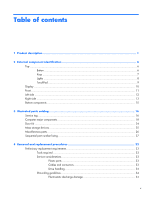
storage devices ...25 Miscellaneous parts ...26 Sequential part number listing 27 4 Removal and replacement procedures 33 Preliminary replacement requirements 33 Tools required ...33 Service considerations 33 Plastic parts 33 Cables and connectors 33 Drive handling 34 Grounding guidelines 34 - HP ENVY 14-1210nr | HP ENVY 14 Notebook PC - Maintenance and Service Guide - Page 6
replacement procedures 38 Service tag ...38 Computer feet ...39 Battery ...39 SIM ...41 Mass storage device 41 WWAN module ...44 WLAN module ...47 RTC battery ...51 Memory module ...52 Battery 86 Computer specifications ...86 14.5-inch, SVA display specifications 87 Hard drive specifications ...88 - HP ENVY 14-1210nr | HP ENVY 14 Notebook PC - Maintenance and Service Guide - Page 7
partition 92 Recovering using the recovery discs 92 Backing up your information ...93 Using Windows Backup and Restore 93 Using system restore points 94 When to create restore points for specific countries and regions 99 10 Recycling ...100 Battery ...100 Display ...100 Index ...106 vii - HP ENVY 14-1210nr | HP ENVY 14 Notebook PC - Maintenance and Service Guide - Page 8
viii - HP ENVY 14-1210nr | HP ENVY 14 Notebook PC - Maintenance and Service Guide - Page 9
Category Product Name Processors Description HP ENVY 14 Notebook PC Intel Core i7-840QM 1.86- to 3.06-GHz, 45W turbo processor (1333-MHz FSB, 8-MB L3 cache, Quad Core) Intel Core i7-820QM 1.73- to 3.06-GHz, 45W turbo processor (1333-MHz FSB, 6-MB L3 cache, Quad Core) Intel Core i7-740QM 1.73- to - HP ENVY 14-1210nr | HP ENVY 14 Notebook PC - Maintenance and Service Guide - Page 10
Express chipset Platform controller hub (PCH): Ibex Peak-M Unified memory architecture (UMA, integrated) with shared video memory, memory size is dynamic change Intel HD Graphics Supports BD playback with HD decode, DX10.1 support and HDMI support 14.5-in, high-definition+ (HD+), radiance LED, WVA - HP ENVY 14-1210nr | HP ENVY 14 Notebook PC - Maintenance and Service Guide - Page 11
(WLAN) options by way of wireless module Two WLAN antennas built into display assembly Support for the following WLAN formats: ● Broadcom 43224 802.11a/b/g/n 2×2 WiFi Adapter ● Intel Centrino Advanced-N 6200 802.11a/b/g/n 2×2 WLAN module ● Intel Centrino Advanced-N 6200 802.11a/b/g 2x2 WLAN module - HP ENVY 14-1210nr | HP ENVY 14 Notebook PC - Maintenance and Service Guide - Page 12
-45 (Ethernet, includes link and activity lights) ● USB 2.0 (3) Keyboard/ Full-size (14.5 in), backlit, island-style keyboard pointing devices f5/f6 control for backlight brightness TouchPad with gesture support (HP-defined, scroll, pinch, zoom) Taps enabled by default Power requirements 90W - HP ENVY 14-1210nr | HP ENVY 14 Notebook PC - Maintenance and Service Guide - Page 13
system Serviceability Description Preinstalled: ● Windows® 7 Home Premium 64-bit ● Windows 7 Home Professional 64-bit ● Windows 7 Ultimate 64-bit ● Linux (configurable with embedded HP QuickWeb End-user replaceable parts: ● AC adapter ● Battery ● Hard drive ● Memory modules (2) ● RTC battery ● WLAN - HP ENVY 14-1210nr | HP ENVY 14 Notebook PC - Maintenance and Service Guide - Page 14
to exit Sleep. ● When the computer is in Hibernation, press the button briefly to exit Hibernation. If the computer has stopped responding and Windows shutdown procedures are ineffective, press and hold the power button for at least 5 seconds to turn off the computer. To learn more about your - HP ENVY 14-1210nr | HP ENVY 14 Notebook PC - Maintenance and Service Guide - Page 15
system information when pressed in combination with the fn key. Displays system information when pressed in combination with the esc key. Displays the Windows Start menu. Displays a shortcut menu for items beneath the pointer. Execute frequently used functions. Ejects the optical drive. Top 7 - HP ENVY 14-1210nr | HP ENVY 14 Notebook PC - Maintenance and Service Guide - Page 16
Lights Item (1) Component TouchPad off indicator (2) Power light (3) Mute light (4) Wireless light Description ● Amber: The TouchPad is off. ● Off: The TouchPad is on. ● White: The computer is on. ● Blinking white: The computer is in the Sleep state. ● Off: The computer is off or in - HP ENVY 14-1210nr | HP ENVY 14 Notebook PC - Maintenance and Service Guide - Page 17
off. Quickly double-tap the TouchPad off indicator to turn the TouchPad on and off. Moves the pointer and selects or activates items on the screen. Functions like the left button on an external mouse. Functions like the right button on an external mouse. Top 9 - HP ENVY 14-1210nr | HP ENVY 14 Notebook PC - Maintenance and Service Guide - Page 18
and captures still photographs. To access the webcam, select Start > All Programs > HP > HP MediaSmart > HP MediaSmart Webcam. (5) Webcam light On: The webcam is in use. *The antennas or region. These notices are located in Help and Support. 10 Chapter 2 External component identification - HP ENVY 14-1210nr | HP ENVY 14 Notebook PC - Maintenance and Service Guide - Page 19
(3) Component Speakers (2) Bluetooth compartment Digital Media Slot Description Produce sound. Contains a Bluetooth device. Supports the following digital card formats: ● MultiMediaCard ● Secure Digital (SD) Memory Card ● Secure Digital High Capacity Memory card ● Secure Digital Extended Capacity - HP ENVY 14-1210nr | HP ENVY 14 Notebook PC - Maintenance and Service Guide - Page 20
a device is connected to the jack, the computer speakers are disabled. NOTE: Be sure that the device cable has a 4conductor connector that supports both audio-out (headphone) and audio-in (microphone). Produces sound when connected to optional powered stereo speakers, headphones, ear buds, a headset - HP ENVY 14-1210nr | HP ENVY 14 Notebook PC - Maintenance and Service Guide - Page 21
Hard Drive Protection has temporarily parked the hard drive. NOTE: For information on HP ProtectSmart Hard Drive Protection, refer to the HP Notebook Reference Guide. Connects a high-performance eSATA component, such as an eSATA external hard drive, or connects an optional USB device. Connects - HP ENVY 14-1210nr | HP ENVY 14 Notebook PC - Maintenance and Service Guide - Page 22
power. ● Blinking amber: The battery has reached a low battery level, a critical battery level, or there is a battery error. ● Amber: A battery is charging. ● White: The computer is connected to external power and the battery is fully charged. Connects an AC adapter. 14 Chapter 2 External component - HP ENVY 14-1210nr | HP ENVY 14 Notebook PC - Maintenance and Service Guide - Page 23
(3) SIM slot (select models only) (4) Accessory battery connector (5) Battery cover release latch (6) Battery bay Description Contains the memory module slots and a wireless WAN module. CAUTION: To prevent an unresponsive system, replace the wireless module with a wireless module authorized - HP ENVY 14-1210nr | HP ENVY 14 Notebook PC - Maintenance and Service Guide - Page 24
tag When ordering parts or requesting information, provide the computer serial number and model number provided on the service tag. Item (1) (2) (3) Component Product name Serial number (s/n) Part number/Product number (p/n) 16 Chapter 3 Illustrated parts catalog Description This is the product - HP ENVY 14-1210nr | HP ENVY 14 Notebook PC - Maintenance and Service Guide - Page 25
Item (4) (5) Component Warranty period Model description Description This number describes the duration of the warranty period for the computer. This is the alphanumeric identifier used to locate documents, drivers, and support for the computer. Service tag 17 - HP ENVY 14-1210nr | HP ENVY 14 Notebook PC - Maintenance and Service Guide - Page 26
Computer major components 18 Chapter 3 Illustrated parts catalog - HP ENVY 14-1210nr | HP ENVY 14 Notebook PC - Maintenance and Service Guide - Page 27
Item (1) (2) Description Spare part number 14.5-in, LED, HD, AntiGlare, flush glass display assembly (includes display panel cable, webcam/ microphone module and cable, 2 WLAN antenna cables and transceivers, and 2 WWAN antenna - HP ENVY 14-1210nr | HP ENVY 14 Notebook PC - Maintenance and Service Guide - Page 28
cable 608380-001 Door Kit: For use only with Beats Edition computer models: 629879-001 For use only with standard computer models: 608384-001 Includes: Battery cover Memory module/wireless module compartment cover 20 Chapter 3 Illustrated parts catalog - HP ENVY 14-1210nr | HP ENVY 14 Notebook PC - Maintenance and Service Guide - Page 29
MHz FSB, 3-MB L3 625824-001 cache, Dual Core) Intel Core i5-540M 2.53-GHz, 35W turbo processor (1066-MHz FSB, 3-MB L3 cache, Dual Core) 594188-001 Intel Core i5-520M 2.40-GHz, 35W turbo processor (1066-MHz FSB, 3-MB L3 cache, Dual Core) 594187-001 Intel Core i5-480M 2.66- to 2.93-GHz, 35W turbo - HP ENVY 14-1210nr | HP ENVY 14 Notebook PC - Maintenance and Service Guide - Page 30
Item (13) (14) (15) (16) (17) (18) (19) (20) Description Intel Core i3-350M 2.26-GHz, 25W processor (1066-MHz FSB, 3-MB L3 cache, Dual Core) Intel Pentium P6200 2.13-GHz processor (1066-MHz FSB, 3-MB L3 cache) Intel Pentium P6100 2.00-GHz processor (1066-MHz FSB, 3-MB L3 cache) Intel Pentium P6000 - HP ENVY 14-1210nr | HP ENVY 14 Notebook PC - Maintenance and Service Guide - Page 31
-MB 598859-001 RTC battery (includes cable and double , Honduras, Hong Kong, Hungary, Iceland, India, Indonesia, Ireland, Italy, the Ivory Coast Intel Centrino Advanced-N 6200 802.11a/b/g/n 2×2 WLAN module 572509-001 Intel Centrino Advanced-N 6200 802.11a/b/g 2×2 WLAN module 572510-001 Intel - HP ENVY 14-1210nr | HP ENVY 14 Notebook PC - Maintenance and Service Guide - Page 32
Door Kit Item (1) (2) Description Door Kit: For use only with Beats Edition computer models: For use only with standard computer models: Includes: Battery cover Memory module/wireless module compartment cover Spare part number 629879-001 608384-001 24 Chapter 3 Illustrated parts catalog - HP ENVY 14-1210nr | HP ENVY 14 Notebook PC - Maintenance and Service Guide - Page 33
Mass storage devices Item (1) (2) Description Spare part number Hard drive (includes hard drive bracket and screws): 750-GB, 7200-rpm 633252-001 640-GB, 7200-rpm 621046-001 640-GB, 5400-rpm 631161-001 500-GB, 7200-rpm 634919-001 320-GB, 7200-rpm 603783-001 250-GB, 7200-rpm 608369-001 - HP ENVY 14-1210nr | HP ENVY 14 Notebook PC - Maintenance and Service Guide - Page 34
RC/V HP Smart AC adapter 90W PFC RC/V EM HP Smart AC adapter 90W PFC RC/V EM 3W HDMI to VGA adapter Power cord: For use in Argentina For use in Italy For use in Australia For use in Thailand For use in Brazil For use in Denmark For use in Europe, the Middle East, and Africa For use in India - HP ENVY 14-1210nr | HP ENVY 14 Notebook PC - Maintenance and Service Guide - Page 35
Power cord for use in Argentina Power cord for use in India HDMI to VGA adapter HSPA EV-DO WWAN module Intel Centrino Advanced-N 6200 802.11a/b/g/n 2×2 WLAN module Intel Centrino Advanced-N 6200 802.11a/b/g 2×2 WLAN module RTC battery (includes cable and double-sided tape) Broadcom 43224 802.11a - HP ENVY 14-1210nr | HP ENVY 14 Notebook PC - Maintenance and Service Guide - Page 36
Hungary, Iceland, India, Indonesia, Ireland memory module (PC3, 10600, 1333-MHz) 6-cell, 62-Wh, 2.80-Ah, Li-ion battery 320-GB, 7200-rpm hard drive (includes hard drive bracket) System board for use only on computer models equipped with an Intel Core i5, i3, or Pentium processor (includes replacement - HP ENVY 14-1210nr | HP ENVY 14 Notebook PC - Maintenance and Service Guide - Page 37
-051 608375-061 608375-071 608375-121 608375-131 608375-141 608375-161 608375-171 608375-201 608375-251 608375-281 608375-291 Description 14.5-in, LED, HD+, AntiGlare, flush glass WVA display assembly for use only on standard computer models (includes display panel cable, webcam/microphone module - HP ENVY 14-1210nr | HP ENVY 14 Notebook PC - Maintenance and Service Guide - Page 38
(includes the battery cover and the memory module/ wireless module compartment cover) NOTE: See Door Kit on page 24 for more Door Kit component information. Cable Kit (includes the Bluetooth module cable) 90W PFC RC/V HP Smart AC adapter 90W PFC RC/V EM HP Smart AC adapter Intel Core i7-740QM 1.73 - HP ENVY 14-1210nr | HP ENVY 14 Notebook PC - Maintenance and Service Guide - Page 39
AD1 Description Intel Pentium P6100 20-GHz processor (1066-MHz, 3-MB L3 cache; includes replacement thermal material) Power cord for use in North America 14.5-in, , and 2 WWAN antenna cables and transceivers) Battery connector board (includes cable) 14.5-in, LED, HD, AntiGlare, flush glass SVA - HP ENVY 14-1210nr | HP ENVY 14 Notebook PC - Maintenance and Service Guide - Page 40
L3 cache; includes replacement thermal material) Intel Core i5-460M 2.53-GHz, 35W turbo processor (1066-MHz FSB, 3-MB L3 cache, Dual Core; includes replacement thermal material) Door Kit for use only with Beats Edition computer models (includes the battery cover and the memory module/wireless module - HP ENVY 14-1210nr | HP ENVY 14 Notebook PC - Maintenance and Service Guide - Page 41
removal and replacement procedures: ● Flat-bladed screwdriver ● Magnetic screwdriver ● Phillips P0 and P1 screwdrivers Service considerations The only at the points designated in the maintenance instructions. Cables and connectors CAUTION: When servicing the computer, be sure that cables are placed - HP ENVY 14-1210nr | HP ENVY 14 Notebook PC - Maintenance and Service Guide - Page 42
at all and can work perfectly throughout a normal cycle. Or the device may function normally for a while, then degrade in the internal layers, reducing its life expectancy. 34 Chapter 4 Removal and replacement procedures - HP ENVY 14-1210nr | HP ENVY 14 Notebook PC - Maintenance and Service Guide - Page 43
box Typical electrostatic voltage levels Relative humidity 10% 40% 35,000 V 15,000 V 12,000 V 5,000 V 6,000 V 800 V 2,000 V 700 V 11,500 V 4,000 V 14,500 V 5,000 V 26,500 V 20,000 V 21,000 V 11,000 V 55% 7,500 V 3,000 V 400 V 400 V 2,000 V 3,500 V 7,000 V 5,000 V Preliminary - HP ENVY 14-1210nr | HP ENVY 14 Notebook PC - Maintenance and Service Guide - Page 44
properly grounded work surface and use properly grounded tools and equipment. ● Use conductive field service tools, such as cutters, screwdrivers, and vacuums. ● When fixtures must directly contact inserting or removing connectors or test equipment. 36 Chapter 4 Removal and replacement procedures - HP ENVY 14-1210nr | HP ENVY 14 Notebook PC - Maintenance and Service Guide - Page 45
resistance ● Static-dissipative tables or floor mats with hard ties to the ground ● Field service kits ● Static awareness labels ● Material-handling packages ● Nonconductive plastic bags, tubes, or Floor mats Voltage protection level 1,500 V 7,500 V 5,000 V Preliminary replacement requirements 37 - HP ENVY 14-1210nr | HP ENVY 14 Notebook PC - Maintenance and Service Guide - Page 46
product's hardware components. The part number helps a service technician determine what components and parts are needed. This number describes the duration of the warranty period for the computer. This is the alphanumeric identifier used to locate documents, drivers, and support for the computer. - HP ENVY 14-1210nr | HP ENVY 14 Notebook PC - Maintenance and Service Guide - Page 47
power from the computer by first unplugging the power cord from the AC outlet and then unplugging the AC adapter from the computer. Remove the battery: 1. Slide the battery cover release latch (1). (The battery cover releases forward (2)). Component replacement procedures 39 - HP ENVY 14-1210nr | HP ENVY 14 Notebook PC - Maintenance and Service Guide - Page 48
the rear edge of the battery down into the battery bay until it is seated. 3. Slide the right battery release latch to lock the battery into place. (The left battery release latch will automatically lock into place.) 4. Replace the battery cover, and then slide the battery cover back until it is - HP ENVY 14-1210nr | HP ENVY 14 Notebook PC - Maintenance and Service Guide - Page 49
by first unplugging the power cord from the AC outlet and then unplugging the AC adapter from the computer. 4. Remove the battery cover and battery (see Battery on page 39). Remove the memory module: 1. Press in on the SIM (1) to release it from the SIM slot. 2. Remove the SIM (2) from the SIM slot - HP ENVY 14-1210nr | HP ENVY 14 Notebook PC - Maintenance and Service Guide - Page 50
power from the computer by first unplugging the power cord from the AC outlet and then unplugging the AC adapter from the computer. 4. Remove the battery cover and battery (see Battery on page 39). 42 Chapter 4 Removal and replacement procedures - HP ENVY 14-1210nr | HP ENVY 14 Notebook PC - Maintenance and Service Guide - Page 51
disconnect it from the system board. 3. Lift the mass storage device (2) out of the mass storage device bay. 4. If it is necessary to replace the mass storage device bracket, remove the four Phillips PM3.0×3.0 screws (1) that secure the bracket to the mass storage device. 5. Remove the mass storage - HP ENVY 14-1210nr | HP ENVY 14 Notebook PC - Maintenance and Service Guide - Page 52
you replace the module and then receive a warning message, remove the module to restore device functionality, and then contact technical support. then unplugging the AC adapter from the computer. 4. Remove the battery cover and battery (see Battery on page 39). 5. Remove the hard drive (see Mass - HP ENVY 14-1210nr | HP ENVY 14 Notebook PC - Maintenance and Service Guide - Page 53
connected to the terminals on the WWAN module, the protective sleeves must be installed on the antenna connectors, as shown in the following illustration. Component replacement procedures 45 - HP ENVY 14-1210nr | HP ENVY 14 Notebook PC - Maintenance and Service Guide - Page 54
Reverse this procedure to install the WWAN module. 46 Chapter 4 Removal and replacement procedures - HP ENVY 14-1210nr | HP ENVY 14 Notebook PC - Maintenance and Service Guide - Page 55
Hungary, Iceland, India, Indonesia, Ireland, Intel Centrino Wireless-N + WiMAX 6150 WLAN module 619997-001 CAUTION: To prevent an unresponsive system, replace replace the module and then receive a warning message, remove the module to restore device functionality, and then contact technical support - HP ENVY 14-1210nr | HP ENVY 14 Notebook PC - Maintenance and Service Guide - Page 56
module compartment cover. The memory module/wireless module compartment cover is included in the Door Kit, spare part numbers 608384-001 (for use only with standard computer models) and 629879-001 (for use only with Beats Edition computer models). 48 Chapter 4 Removal and replacement procedures - HP ENVY 14-1210nr | HP ENVY 14 Notebook PC - Maintenance and Service Guide - Page 57
WLAN module 2/Aux terminal. 5. Remove the two Phillips PM2.0×3.0 screws that secure the WLAN module to the system board. (The WLAN module tilts up.) Component replacement procedures 49 - HP ENVY 14-1210nr | HP ENVY 14 Notebook PC - Maintenance and Service Guide - Page 58
must be installed on the antenna connectors, as shown in the following illustration. Reverse this procedure to install the WLAN module. 50 Chapter 4 Removal and replacement procedures - HP ENVY 14-1210nr | HP ENVY 14 Notebook PC - Maintenance and Service Guide - Page 59
from the computer. 4. Remove the battery cover and battery (see Battery on page 39). 5. Remove the memory module/wireless module compartment cover (see WLAN module on page 47). Remove the RTC battery: 1. Disconnect the RTC battery cable from the system board. Component replacement procedures 51 - HP ENVY 14-1210nr | HP ENVY 14 Notebook PC - Maintenance and Service Guide - Page 60
power from the computer by first unplugging the power cord from the AC outlet and then unplugging the AC adapter from the computer. 4. Remove the battery cover and battery (see Battery on page 39). 5. Remove the memory module/wireless module compartment cover (see WLAN module on page 47). Remove the - HP ENVY 14-1210nr | HP ENVY 14 Notebook PC - Maintenance and Service Guide - Page 61
2. Remove the memory module (2) by pulling it away from the slot at an angle. Reverse this procedure to install a memory module. Component replacement procedures 53 - HP ENVY 14-1210nr | HP ENVY 14 Notebook PC - Maintenance and Service Guide - Page 62
and then unplugging the AC adapter from the computer. 4. Remove the battery cover and battery (see Battery on page 39). 5. Remove the memory module/wireless module compartment cover (see WLAN module on page 47). Remove the battery connector board: 1. Remove the Mylar cover (1) located at the base of - HP ENVY 14-1210nr | HP ENVY 14 Notebook PC - Maintenance and Service Guide - Page 63
battery charger board (1) up and forward until it rests upside down in the battery bay. 6. Disconnect the power extension cable (2) from the battery charger board. 7. Remove the battery charger board (3). Reverse this procedure to install the battery charger board. Component replacement procedures - HP ENVY 14-1210nr | HP ENVY 14 Notebook PC - Maintenance and Service Guide - Page 64
cover and battery (see Battery on page 39). 5. Remove the memory module/wireless module compartment cover (see WLAN module on page 47). Remove the top cover: 1. Remove the eight Phillips PM2.5×7.0 screws that secure the top cover to the computer. 56 Chapter 4 Removal and replacement procedures - HP ENVY 14-1210nr | HP ENVY 14 Notebook PC - Maintenance and Service Guide - Page 65
2. Remove the three Phillips PM2.0×3.0 screws that secure the top cover to the computer in the battery bay. 3. Turn the computer right side up, with the front toward you. 4. Open the light cable is attached, and then disconnect the cable (4) from the system board. Component replacement procedures 57 - HP ENVY 14-1210nr | HP ENVY 14 Notebook PC - Maintenance and Service Guide - Page 66
-251 619400-171 619400-AD1 619400-071 619400-BG1 619400-AD1 619400-281 619400-031 619400-001 608375-131 608375-251 58 Chapter 4 Removal and replacement procedures - HP ENVY 14-1210nr | HP ENVY 14 Notebook PC - Maintenance and Service Guide - Page 67
and then unplugging the AC adapter from the computer. 4. Remove the battery cover and battery (see Battery on page 39). 5. Remove the memory module/wireless module compartment cover (see WLAN module on page 47). until the keyboard disengages from the top cover. Component replacement procedures 59 - HP ENVY 14-1210nr | HP ENVY 14 Notebook PC - Maintenance and Service Guide - Page 68
edge of keyboard disengage from the slots in the top cover. 7. Remove the keyboard. Reverse this procedure to install the keyboard. 60 Chapter 4 Removal and replacement procedures - HP ENVY 14-1210nr | HP ENVY 14 Notebook PC - Maintenance and Service Guide - Page 69
then unplugging the AC adapter from the computer. 4. Remove the battery cover and battery (see Battery on page 39). 5. Remove the memory module/wireless module compartment cover (see WLAN module on page 47). that secures the audio/USB board to the base enclosure. Component replacement procedures 61 - HP ENVY 14-1210nr | HP ENVY 14 Notebook PC - Maintenance and Service Guide - Page 70
unplugging the power cord from the AC outlet and then unplugging the AC adapter from the computer. 4. Remove the battery cover and battery (see Battery on page 39). 5. Remove the memory module/wireless module compartment cover (see WLAN module on page 47). 6. Remove the top cover (see Top cover on - HP ENVY 14-1210nr | HP ENVY 14 Notebook PC - Maintenance and Service Guide - Page 71
the computer by first unplugging the power cord from the AC outlet and then unplugging the AC adapter from the computer. 4. Remove the battery cover and battery (see Battery on page 39), and then remove the following components: a. SIM (see SIM on page 41) b. Hard drive (see Mass storage device on - HP ENVY 14-1210nr | HP ENVY 14 Notebook PC - Maintenance and Service Guide - Page 72
c. WWAN module (see WWAN module on page 44) d. Memory module/wireless module compartment cover (see WLAN module on page 47) e. Top cover (see Top cover on page 56) WWAN board (5) and cable. Reverse this procedure to install the SIM/WWAN board and cable. 64 Chapter 4 Removal and replacement procedures - HP ENVY 14-1210nr | HP ENVY 14 Notebook PC - Maintenance and Service Guide - Page 73
and then unplugging the AC adapter from the computer. 4. Remove the battery cover and battery (see Battery on page 39). 5. Remove the memory module/wireless module compartment cover (see WLAN module on page 47). computer right-side up, with the front toward you. Component replacement procedures 65 - HP ENVY 14-1210nr | HP ENVY 14 Notebook PC - Maintenance and Service Guide - Page 74
Phillips PM2.0×3.0 screws (1) that secure the optical drive to the base enclosure. 7. Remove the optical drive (2). 8. If it is necessary to replace the optical drive retention rails: a. Remove the four Philllips PM2.0×3.0 screws (1) that secure the retention rails to the optical drive. b. Remove - HP ENVY 14-1210nr | HP ENVY 14 Notebook PC - Maintenance and Service Guide - Page 75
9. If it is necessary to replace the optical drive connector board: a. Remove the Philllips PM2 then unplugging the AC adapter from the computer. 4. Remove the battery cover and battery (see Battery on page 39). 5. Remove the memory module/wireless module compartment cover (see WLAN module on page - HP ENVY 14-1210nr | HP ENVY 14 Notebook PC - Maintenance and Service Guide - Page 76
battery replacement thermal material. Replacement thermal material is also available in the Thermal Material Kit, spare part number 634366-001. Description For use only on computer models equipped with an Intel Core i7 processor For use only on computer models equipped with an Intel Core i5 - HP ENVY 14-1210nr | HP ENVY 14 Notebook PC - Maintenance and Service Guide - Page 77
components are removed from the defective system board and installed on the replacement system board: ● SIM (see SIM on page 41) ● WLAN module (see WLAN module on page 47) ● RTC battery (see RTC battery on page 51) ● Memory module (see Memory module on page 52) ● Fan/heat sink assembly (see Fan/heat - HP ENVY 14-1210nr | HP ENVY 14 Notebook PC - Maintenance and Service Guide - Page 78
. 3. Disconnect the display panel cable (1) from the system board. 4. Disconnect the power connector cable (2) from the system board. 5. Disconnect the power extension cable (3) from the battery connector board. 70 Chapter 4 Removal and replacement procedures - HP ENVY 14-1210nr | HP ENVY 14 Notebook PC - Maintenance and Service Guide - Page 79
.5×5.0 screws that secure the system board to the base enclosure. 8. Lift the left side of the system board (1) until it rests at an angle. Component replacement procedures 71 - HP ENVY 14-1210nr | HP ENVY 14 Notebook PC - Maintenance and Service Guide - Page 80
AC adapter from the computer. 4. Remove the battery cover and battery (see Battery on page 39). 5. Remove the hard drive (see Mass storage device on page 41). 6. Remove the memory module/wireless module compartment cover (see WLAN module on page 47). 72 Chapter 4 Removal and replacement procedures - HP ENVY 14-1210nr | HP ENVY 14 Notebook PC - Maintenance and Service Guide - Page 81
board ribbon cable from the system board (see Battery connector board on page 54). 8. Remove the top the heat sink section (4) that services it ● Thermal paste is used on the graphics subsystem chip (5) and the heat sink section (6) that services it Replacement thermal material is included with all - HP ENVY 14-1210nr | HP ENVY 14 Notebook PC - Maintenance and Service Guide - Page 82
-MHz FSB, 3-MB L3 cache, Dual Core) 594188-001 Intel Core i5-520M 2.40-GHz, 35W turbo processor (1066-MHz FSB, 3-MB L3 cache, Dual Core) 594187-001 Intel Core i5-480M 2.66-GHz, 35W turbo processor (1066-MHz FSB, 3-MB L3 cache, Dual Core) 634693-001 Intel Core i5-460M 2.53-GHz, 35W turbo processor - HP ENVY 14-1210nr | HP ENVY 14 Notebook PC - Maintenance and Service Guide - Page 83
AC outlet and then unplugging the AC adapter from the computer. 4. Remove the battery cover and battery (see Battery on page 39). 5. Remove the hard drive (see Mass storage device on page 41). 6. Remove the memory module/wireless module compartment cover (see WLAN module on page 47). 7. Disconnect - HP ENVY 14-1210nr | HP ENVY 14 Notebook PC - Maintenance and Service Guide - Page 84
with the triangle icon (4) embossed on the processor socket when you install the processor. Reverse this procedure to install the processor. 76 Chapter 4 Removal and replacement procedures - HP ENVY 14-1210nr | HP ENVY 14 Notebook PC - Maintenance and Service Guide - Page 85
computer. 4. Remove the battery cover and battery (see Battery on page 39). 5. Remove the hard drive (see Mass storage device on page 41). 6. Remove the memory module/wireless module compartment cover screws (2) that secure the speakers to the base enclosure. Component replacement procedures 77 - HP ENVY 14-1210nr | HP ENVY 14 Notebook PC - Maintenance and Service Guide - Page 86
and transceivers, and 2 WWAN antenna cables and transceivers. Description Spare part number 14.5-in, LED, HD, AntiGlare, flush glass SVA display assembly for use only the computer. 4. Remove the battery cover and battery (see Battery on page 39). 78 Chapter 4 Removal and replacement procedures - HP ENVY 14-1210nr | HP ENVY 14 Notebook PC - Maintenance and Service Guide - Page 87
5. Remove the memory module/wireless module compartment cover (see WLAN support the display assembly can result in damage to the display assembly and other computer components. 9. Remove the four Phillips PM2.5×4.0 screws (4) that secure the display assembly to the computer. Component replacement - HP ENVY 14-1210nr | HP ENVY 14 Notebook PC - Maintenance and Service Guide - Page 88
10. Remove the display assembly (5). Reverse this procedure to reassemble the display assembly. 80 Chapter 4 Removal and replacement procedures - HP ENVY 14-1210nr | HP ENVY 14 Notebook PC - Maintenance and Service Guide - Page 89
of the computer, and the amount of system and extended memory. CAUTION: Use extreme care when making changes in Setup Utility ESC key for Startup Menu" message is displayed in the lower-left corner of the screen, press esc. When the Startup Menu is displayed, press f10. Using Setup Utility Changing - HP ENVY 14-1210nr | HP ENVY 14 Notebook PC - Maintenance and Service Guide - Page 90
Navigating and selecting in Setup Utility Because Setup Utility is not Windows based, it does not support the TouchPad. Navigation and selection are by keystroke. ● To choose a menu or a menu item, use the arrow keys. ● To choose an item in a list or - HP ENVY 14-1210nr | HP ENVY 14 Notebook PC - Maintenance and Service Guide - Page 91
HP Web site. Most BIOS updates on the HP Web site are packaged in compressed files called SoftPaqs. Some download packages contain a file named Readme.txt, which contains information regarding installing and troubleshooting fn +esc (if you are already in Windows) or by using Setup Utility. 1. Start - HP ENVY 14-1210nr | HP ENVY 14 Notebook PC - Maintenance and Service Guide - Page 92
1. Access the page on the HP Web site that provides software for your computer: Windows 7-Select Start > Help and Support > Maintain. Windows XP-Select Start > Help and Support, and then select the software and drivers update. 2. Follow the on-screen instructions to identify your computer and access - HP ENVY 14-1210nr | HP ENVY 14 Notebook PC - Maintenance and Service Guide - Page 93
NOTE: After a message on the screen reports a successful installation, you can delete the downloaded file from your hard drive. Updating the BIOS 85 - HP ENVY 14-1210nr | HP ENVY 14 Notebook PC - Maintenance and Service Guide - Page 94
Nonoperating Maximum altitude (unpressurized) Operating (14.7 to 10.1 psia) Nonoperating (14.7 to 4.4 psia) Shock Operating Nonoperating Random vibration Operating Metric U.S. 35.6 cm 23.70 cm 2.77 cm to 2.82 cm 2.38 kg 14.02 in 9.33 in 1.09 in to 1.11 in 5.25 lbs 19.0 V dc @ 4.74 - HP ENVY 14-1210nr | HP ENVY 14 Notebook PC - Maintenance and Service Guide - Page 95
: Applicable product safety standards specify thermal limits for plastic surfaces. The computer operates well within this range of temperatures. 14.5-inch, SVA display specifications Dimensions Width Height Diagonal Number of colors Contrast ratio Brightness Backlight Character display Total power - HP ENVY 14-1210nr | HP ENVY 14 Notebook PC - Maintenance and Service Guide - Page 96
referring to hard drive storage capacity. Actual accessible capacity is less. Actual drive specifications may differ slightly. NOTE: Certain restrictions and exclusions apply. Contact technical support for details. 88 Chapter 6 Specifications - HP ENVY 14-1210nr | HP ENVY 14 Notebook PC - Maintenance and Service Guide - Page 97
DVD±RW and CD-RW Super Multi Double-Layer Combo Drive specifications Applicable disc Access time Random Cache buffer Data transfer rate 24X CD-ROM 8X DVD 24X CD-R 16X CD-RW 8X DVD+R 4X DVD+RW 8X DVD-R 4X DVD-RW 2.4X DVD+R(9) 5X DVD-RAM Transfer mode Read: Write: CD-DA, CD+(E)G, CD-MIDI, CD-TEXT, - HP ENVY 14-1210nr | HP ENVY 14 Notebook PC - Maintenance and Service Guide - Page 98
Backing up your information ● Creating system restore points ● Recovering a program or driver ● Performing a full system recovery (from the partition or recovery discs) NOTE: Disk Management. If the partition is present, an HP Recovery drive is listed in the window. 90 Chapter 7 Backup and recovery - HP ENVY 14-1210nr | HP ENVY 14 Notebook PC - Maintenance and Service Guide - Page 99
separately) to create recovery discs, or you can purchase recovery discs for your computer from the HP Web site. If you use an external optical drive, it must be connected directly to a USB Programs > Recovery Manager > Recovery Disc Creation. 2. Follow the on-screen instructions. Recovery discs 91 - HP ENVY 14-1210nr | HP ENVY 14 Notebook PC - Maintenance and Service Guide - Page 100
be downloaded from the manufacturer's Web site or reinstalled from the disc provided by the manufacturer. Recovering screen. Then, press f11 while the "F11 (HP Recovery)" message is displayed on the screen. 2. Click System Recovery in the Recovery Manager window. 3. Follow the on-screen instructions - HP ENVY 14-1210nr | HP ENVY 14 Notebook PC - Maintenance and Service Guide - Page 101
and Security > Backup and Restore. 2. Follow the on-screen instructions to schedule and create a backup. NOTE: Windows includes the User Account Control feature to improve the security of , or changing Windows settings. Refer to Help and Support for more information. Backing up your information 93 - HP ENVY 14-1210nr | HP ENVY 14 Notebook PC - Maintenance and Service Guide - Page 102
Start > Control Panel > System and Security > System. 2. In the left pane, click System Protection. 3. Click the System Protection tab. 4. Follow the on-screen instructions. Restore to a previous date and time To revert to a restore point (created at a previous date and time), when the computer was - HP ENVY 14-1210nr | HP ENVY 14 Notebook PC - Maintenance and Service Guide - Page 103
8 Connector pin assignments Audio-in (microphone) Pin 1 2 3 Audio-out (headphone) Signal Audio signal in Audio signal in Ground Pin Signal 1 Audio out, left channel 2 Audio out, right channel 3 Ground Audio-in (microphone) 95 - HP ENVY 14-1210nr | HP ENVY 14 Notebook PC - Maintenance and Service Guide - Page 104
HDMI Pin 1 2 3 4 5 6 7 8 9 10 11 12 13 14 15 16 17 18 19 20 Signal TMDS data 2+ TMDS data 2 shield TMDS data 2TMDS data 1+ TMDS data 1 shield TMDS data 1TMDS data 0+ TMDS data 0 - HP ENVY 14-1210nr | HP ENVY 14 Notebook PC - Maintenance and Service Guide - Page 105
RJ-45 (network) Pin 1 2 3 4 5 6 7 8 Universal Serial Bus Signal Transmit + Transmit Receive + Unused Unused Receive Unused Unused Pin Signal 1 +5 VDC 2 Data 3 Data + 4 Ground RJ-45 (network) 97 - HP ENVY 14-1210nr | HP ENVY 14 Notebook PC - Maintenance and Service Guide - Page 106
9 Power cord set requirements The wide-range input feature of the computer permits it to operate from any line voltage from 100 to 120 volts AC, or from 220 to 240 volts AC The 3-conductor power cord set included with the computer meets the requirements for use in the country or region where the - HP ENVY 14-1210nr | HP ENVY 14 Notebook PC - Maintenance and Service Guide - Page 107
Requirements for specific countries and regions Country/region Accredited agency Applicable note number Australia EANSW 1 Austria OVE 1 Belgium CEBC 1 Canada CSA 2 Denmark DEMKO 1 Finland FIMKO 1 France UTE 1 Germany VDE 1 Italy IMQ 1 Japan METI 3 The Netherlands - HP ENVY 14-1210nr | HP ENVY 14 Notebook PC - Maintenance and Service Guide - Page 108
life, do not dispose of the battery in general household waste. Follow the local laws and regulations in your area for computer battery HP product contains mercury in the backlight in the display assembly that might require special handling at end-of-life general disassembly instructions. Specific - HP ENVY 14-1210nr | HP ENVY 14 Notebook PC - Maintenance and Service Guide - Page 109
Perform the following steps: 1. Remove all screw covers (1) and screws (2) that secure the display bezel to the display assembly. 2. Lift up and out on the left and right inside edges (1) and the top and bottom inside edges (2) of the display bezel until the bezel disengages from the display - HP ENVY 14-1210nr | HP ENVY 14 Notebook PC - Maintenance and Service Guide - Page 110
4. Disconnect all display panel cables (1) from the display inverter and remove the inverter (2). 5. Remove all screws (1) that secure the display panel assembly to the display enclosure. 6. Remove the display panel assembly (2) from the display enclosure. 7. Turn the display panel assembly upside - HP ENVY 14-1210nr | HP ENVY 14 Notebook PC - Maintenance and Service Guide - Page 111
10. Remove the display panel frame (2) from the display panel. 11. Remove the screws (1) that secure the backlight cover to the display panel. 12. Lift the top edge of the backlight cover (2) and swing it outward. 13. Remove the backlight cover. 14. Turn the display panel right-side up. Display 103 - HP ENVY 14-1210nr | HP ENVY 14 Notebook PC - Maintenance and Service Guide - Page 112
15. Remove the backlight cables (1) from the clip (2) in the display panel. 16. Turn the display panel upside down. 17. Remove the backlight frame from the display panel. WARNING! The backlight contains mercury. Exercise caution when removing and handling the backlight to avoid damaging this - HP ENVY 14-1210nr | HP ENVY 14 Notebook PC - Maintenance and Service Guide - Page 113
18. Remove the backlight from the backlight frame. 19. Disconnect the display cable (1) from the LCD panel. 20. Remove the screws (2) that secure the LCD panel to the display rear panel. 21. Release the LCD panel (3) from the display rear panel. 22. Release the tape (4) that secures the LCD panel to - HP ENVY 14-1210nr | HP ENVY 14 Notebook PC - Maintenance and Service Guide - Page 114
part numbers 40 battery light 14 battery release latch 15 Bluetooth compartment 11 Bluetooth module removal 62 spare part number 20, 32, 62 bottom components 15 button component 6 buttons power 6 TouchPad 9 C Cable Kit, spare part number 20, 30 cables, service considerations 33 chipset, product - HP ENVY 14-1210nr | HP ENVY 14 Notebook PC - Maintenance and Service Guide - Page 115
Windows logo 7 L left-side components 12 light components 8 lights battery 14 drive 13 mute 8 power 8, 13 webcam 10 wireless 8 M mass storage device removal 41 spare part numbers 22, 25, 28, 29, 32, 41 memory module product description 2 removal 52 spare part numbers 22, 28, 52 memory service - HP ENVY 14-1210nr | HP ENVY 14 Notebook PC - Maintenance and Service Guide - Page 116
serviceability 5 video 3 wireless 3 product name 1, 16, 38 product number 16, 38 protective cover, spare part numbers 26, 32 R removal/replacement preliminaries 33 procedures 38 right-side components 13 RJ-45 jack connector pinout 97 location 13 RTC battery 10 Windows applications key 7 Windows logo
-
 1
1 -
 2
2 -
 3
3 -
 4
4 -
 5
5 -
 6
6 -
 7
7 -
8
-
9
-
10
-
11
-
12
-
13
-
14
-
15
-
16
-
17
-
18
-
19
-
20
-
21
-
22
-
23
-
24
-
25
-
26
-
27
-
28
-
29
-
30
-
31
-
32
-
33
-
34
-
35
-
36
-
37
-
38
-
39
-
40
-
41
-
42
-
43
-
44
-
45
-
46
-
47
-
48
-
49
-
50
-
51
-
52
-
53
-
54
-
55
-
56
-
57
-
58
-
59
-
60
-
61
-
62
-
63
-
64
-
65
-
66
-
67
-
68
-
69
-
70
-
71
-
72
-
73
-
74
-
75
-
76
-
77
-
78
-
79
-
80
-
81
-
82
-
83
-
84
-
85
-
86
-
87
-
88
-
89
-
90
-
91
-
92
-
93
-
94
-
95
-
96
-
97
-
98
-
99
-
100
-
101
-
102
-
103
-
104
-
105
-
106
-
107
-
108
-
109
-
110
-
111
-
112
-
113
-
114
-
115
-
116
 |
 |

HP ENVY 14 Notebook PC
Maintenance and Service Guide