HP EVA P6000 HP Controller Enclosure Riser Assembly Replacement Instructions (
HP EVA P6000 Manual
 |
View all HP EVA P6000 manuals
Add to My Manuals
Save this manual to your list of manuals |
HP EVA P6000 manual content summary:
- HP EVA P6000 | HP Controller Enclosure Riser Assembly Replacement Instructions ( - Page 1
this document For the latest documentation, go to http://www.hp.com/support/ manuals, and select your product. The information contained herein is subject to change without notice. The only warranties for HP products and services are set forth in the express warranty statements accompanying such - HP EVA P6000 | HP Controller Enclosure Riser Assembly Replacement Instructions ( - Page 2
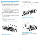
assembly 1. Power down the controller enclosure with HP P6000 Command View or the HP P6000 web-based operator control panel (WOCP). Powering down the controller enclosure also removes power from the disk enclosures. From HP P6000 Command View: a. In the navigation pane, select your storage system - HP EVA P6000 | HP Controller Enclosure Riser Assembly Replacement Instructions ( - Page 3
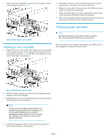
disk enclosures by pressing the power button on the rear power UID bezel of each disk enclosure. 8. Power up the controller enclosure by pressing the power button on the rear power UID bezel of the controller enclosure. Verifying proper operation Figure 4 Removing the riser assembly . Installing
-
 1
1 -
 2
2 -
 3
3
 |
 |

HP Controller Enclosure Riser
Assembly Replacement
Instructions
© Copyright 2009 Hewlett-Packard Development Company, L.P.
Second edition: May 2011
The information in this document is subject to change without notice.
Printed in Puerto Rico
www.hp.com
*593097-001*
About this document
For the latest documentation, go to
h
t
tp://w
w
w
.hp
.co
m/su
ppo
r
t/
man
uals
, and select your product.
The information contained herein is subject to change without notice.
The only warranties for HP products and services are set forth in the
express warranty statements accompanying such products and services.
Nothing herein should be construed as constituting an additional
warranty. HP shall not be liable for technical or editorial errors or
omissions contained herein.
WARRANTY STATEMENT:
To obtain a copy of the warranty for this product, see the warranty
information website:
h
t
tp://w
w
w
.hp
.co
m/go/s
t
o
r
age
w
ar
r
an
t
y
Before you begin
Observe the following precaution when replacing the riser assembly.
CAUTION:
Parts can be damaged by electrostatic discharge. Use proper
anti-static protection. Refer to the documentation that shipped
with your system for additional information.
Your controller enclosure model may vary slightly from what is illustrated
in this document.
Verifying component failure
Use the following method to verify component failure:
Check to see if there is power to the management module or power UID.
If the amber LEDs on the management module or power UID indicate a
failure, the riser assembly may have failed.
NOTE:
An indicated failure of the management module can also be
an indication of failure of the power supply or midplane board.
Page 1