HP EVA P6550 HP StorageWorks disk enclosure fan interconnect board replacement
HP EVA P6550 Manual
 |
View all HP EVA P6550 manuals
Add to My Manuals
Save this manual to your list of manuals |
HP EVA P6550 manual content summary:
- HP EVA P6550 | HP StorageWorks disk enclosure fan interconnect board replacement - Page 1
fan interconnect board replacement instructions About this document For the latest documentation, go to http://www.hp.com/support/ manuals, and select your product. The information contained herein is subject to change without notice. The only warranties for HP products and services are set forth - HP EVA P6550 | HP StorageWorks disk enclosure fan interconnect board replacement - Page 2
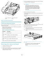
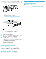
, pull the disk drive out of the drive bays (3), leaving it in the enclosure. Verifying component failure Before replacing the module, check the following and confirm with HP support that it has failed: • Analyze any failure messages received. HP fault monitoring software provides a recommended - HP EVA P6550 | HP StorageWorks disk enclosure fan interconnect board replacement - Page 3
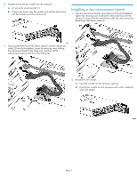
out of the enclosure (2). Installing a fan interconnect board 1. Seat the interconnect board in the chassis (1) from the backplane, tighten the retaining screw holding the interconnect board to the chassis (2) connect the fan interconnect cable (3), and connect the Read Power UID ribbon cable - HP EVA P6550 | HP StorageWorks disk enclosure fan interconnect board replacement - Page 4
each bay, pressing on the lever to secure each drive, remove any labels added to mark the drives. Additional information HP support: http://www.hp.com/support HP support documentation: http://www.hp.com/support/manuals NOTE: Reinstall drives in the same slot locations. 4. Secure the top access
-
 1
1 -
 2
2 -
 3
3 -
 4
4
 |
 |
HP StorageWorks
Disk enclosure fan interconnect
board replacement instructions
This document details the procedures for replacing a
failed fan interconnect board in an HP storage enclos-
ure.
© Copyright 2009 Hewlett-Packard Development Company, L.P.
First edition: June 2009
The information in this document is subject to change without notice.
Printed in the US
www.hp.com
*504222-001*
About this document
For the latest documentation, go to
h
t
tp://w
w
w
.hp
.co
m/su
ppo
r
t/
man
uals
, and select your product.
The information contained herein is subject to change without notice.
The only warranties for HP products and services are set forth in the
express warranty statements accompanying such products and services.
Nothing herein should be construed as constituting an additional
warranty. HP shall not be liable for technical or editorial errors or
omissions contained herein.
WARRANTY STATEMENT: To obtain a copy of the warranty for this
product, see the warranty information website:
h
t
tp://w
w
w
.hp
.co
m/
go/s
t
o
r
age
w
ar
r
an
t
y
Before you begin
Observe the following precautions when replacing a module.
CAUTION:
•
Parts can be damaged by electrostatic discharge. Use proper
anti-static protection. Refer to the documentation that shipped
with your system for additional information.
NOTE:
Illustrations in this document may show modules or a chassis
that differ from your device. However, replacement procedures
are the same for all chassis that use this component.
The interconnect board for each fan is located on the base of the disk
enclosure chassis. See
Figure 1
for the locations.
Page 1