HP EVA6400 HP Enterprise Virtual Array 6400/8400 Expansion Rack Reference Guid
HP EVA6400 Manual
 |
View all HP EVA6400 manuals
Add to My Manuals
Save this manual to your list of manuals |
HP EVA6400 manual content summary:
- HP EVA6400 | HP Enterprise Virtual Array 6400/8400 Expansion Rack Reference Guid - Page 1
HP 6400/8400 Enterprise Virtual Array Expansion Rack Reference Guide Abstract This guide describes how to add an expansion rack to an EVA6400/8400 main rack and is intended for HP-authorized service personnel only. HP Part Number: 5697-1818 Published: March 2012 Edition: 2 - HP EVA6400 | HP Enterprise Virtual Array 6400/8400 Expansion Rack Reference Guid - Page 2
to change without notice. The only warranties for HP products and services are set forth in the express warranty statements accompanying such products and services. Nothing herein should be construed as constituting an additional warranty. HP shall not be liable for technical or editorial errors - HP EVA6400 | HP Enterprise Virtual Array 6400/8400 Expansion Rack Reference Guid - Page 3
...21 Inspect the disk enclosure fan modules 21 3 Connecting the main rack to the expansion rack 23 Routing cables in the expansion rack 23 Online expansion...23 Connecting an EVA6400 multi-product rack to a 0C6D expansion rack 23 General EVA6400 expansion cabling guidelines 25 Connecting an - HP EVA6400 | HP Enterprise Virtual Array 6400/8400 Expansion Rack Reference Guid - Page 4
To add disk enclosures to an EVA6400/8400 in the main rack, see the HP StorageWorks 6400/8400 Enterprise Virtual Array installation guide or the HP Storage EVA6400/8400 M6412A disk enclosure installation instructions for more information. The installation guide contains cabling diagrams for various - HP EVA6400 | HP Enterprise Virtual Array 6400/8400 Expansion Rack Reference Guid - Page 5
per each of the first 3 disk enclosures. Description EVA 42U HP 10000 Intelligent Series rack Power distribution unit (country specific) M6412-A FC disk enclosure HP EVA6400/8400 expansion rack accessory kit, which contains: • HP 5m Multi-mode OM3 LC/LC FC Cable (4) • 4Gb Short Wave FC SFP+ 1 Pack - HP EVA6400 | HP Enterprise Virtual Array 6400/8400 Expansion Rack Reference Guid - Page 6
Figure 1 Rear view of a 2C6D main rack 1. Non-EVA hardware 3. Controllers 2. Disk enclosures 4. Power distribution units 6 Getting started - HP EVA6400 | HP Enterprise Virtual Array 6400/8400 Expansion Rack Reference Guid - Page 7
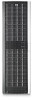
view of a 0C6D expansion rack 1. Disk enclosures 2. Power distribution units 0C9D Expansion rack requirements • One existing 2C18D main rack containing a properly wired controller pair and disk enclosures (see Figure 3 (page 8)). The controllers may be above or in the middle of the disk enclosures - HP EVA6400 | HP Enterprise Virtual Array 6400/8400 Expansion Rack Reference Guid - Page 8
Figure 3 Rear view of a 2C18D main rack 1. Disk enclosures 2. Controllers 3. Power distribution units 8 Getting started - HP EVA6400 | HP Enterprise Virtual Array 6400/8400 Expansion Rack Reference Guid - Page 9
Figure 4 Rear view of a 0C9D expansion rack 1. Disk enclosures 2. Power distribution units 0C9D Expansion rack requirements 9 - HP EVA6400 | HP Enterprise Virtual Array 6400/8400 Expansion Rack Reference Guid - Page 10
a round-hole racks, perform the following steps: IMPORTANT: Do not remove the pins from the ends of the rails unless you are converting the rails for use in round-hole racks. These load-bearing pins are designed to fit through the holes without being removed. 10 Installing disk enclosures into the - HP EVA6400 | HP Enterprise Virtual Array 6400/8400 Expansion Rack Reference Guid - Page 11
) and L (left) stamped into the metal on the front of the rack. Consider the following when installing the rails: • Installing the rails does not require any tools for assembly. • HP recommends you install all the rail kits before installing any other components. • Ensure the rails are level before - HP EVA6400 | HP Enterprise Virtual Array 6400/8400 Expansion Rack Reference Guid - Page 12
12)) and then squeeze the scissor latch together to insert the rail and pins through the rack upright holes until the latch engages (3). Figure 8 Attaching the front rail 3. Loosen the of the way to let you install the chassis in the rails. 12 Installing disk enclosures into the expansion rack - HP EVA6400 | HP Enterprise Virtual Array 6400/8400 Expansion Rack Reference Guid - Page 13
rail gently to be sure it is firmly engaged in the rack and that all latches are engaged in the rack holes. 5. Repeat Step 1 through Step 4 for the other rail. Installing the disk enclosure 1. Remove the bezel covers from each side of the enclosure (see Figure 10 (page 13)). CAUTION: Be careful when - HP EVA6400 | HP Enterprise Virtual Array 6400/8400 Expansion Rack Reference Guid - Page 14
. 5. At the rear of the rack, loosen the thumbscrew on the shipping retaining bracket (1, Figure 15 (page 15)) and slide the bracket forward (2, Figure 15 (page 15)) until the tab engages the slot in the chassis. Tighten the thumbscrew on the bracket. 14 Installing disk enclosures into the expansion - HP EVA6400 | HP Enterprise Virtual Array 6400/8400 Expansion Rack Reference Guid - Page 15
13 Secure rear of enclosure 6. To install disk drives: a. Insert the disk drive into the drive bay (1, Figure 14 (page 15)) until it clicks, locking the drive. b. Rotate the drive lever to the right (2, Figure 14 (page 15)) until it locks. c. Ensure the drives are installed in the proper sequence - HP EVA6400 | HP Enterprise Virtual Array 6400/8400 Expansion Rack Reference Guid - Page 16
for connecting to the controllers and disk enclosures in the main rack. Consider the following: • In these cabling procedures, the left side of the disk enclosure (I/O module A) is cabled and then the right side (I/O module B) is cabled. However, because this cabling is completed before power - HP EVA6400 | HP Enterprise Virtual Array 6400/8400 Expansion Rack Reference Guid - Page 17
in your kit, plug one end into a disk enclosure power supply and the other end into a rack power distribution module. Plug the left power supply into the left module and the right power supply into the right module. 5. Repeat Step 4 for each disk enclosure in the expansion rack. 6. Power on the - HP EVA6400 | HP Enterprise Virtual Array 6400/8400 Expansion Rack Reference Guid - Page 18
one end into a disk enclosure power supply and the other end into a rack power distribution module. Plug the left power supply into the left module and the right power supply into the right module. 6. Repeat Step 5 for each disk enclosure in the expansion rack. 18 Installing disk enclosures into - HP EVA6400 | HP Enterprise Virtual Array 6400/8400 Expansion Rack Reference Guid - Page 19
Step 8 for each disk enclosure in the expansion rack. Figure 19 0C9D expansion rack for the EVA8400 1. Loop 1 2. Loop 2 3. Loop 3 For nine disk enclosures in the expansion rack, complete the following steps: 1. Using 0.41m Fiber Channel copper cables, connect the disk enclosures in the first loop - HP EVA6400 | HP Enterprise Virtual Array 6400/8400 Expansion Rack Reference Guid - Page 20
following conditions: • All enclosures and enclosure modules are properly installed and seated. • Each power supply is connected to one of the electrical outlets in the rack. • The end connector of each cable is plugged into a disk enclosure I/O module. Inspect expansion rack disk drives After the - HP EVA6400 | HP Enterprise Virtual Array 6400/8400 Expansion Rack Reference Guid - Page 21
Solid green - Normal operation Off - Firmware malfunction Flashing amber - Warning condition (not visible when solid amber is displaying) Solid amber - Replace component Off - Normal operation Inspect the disk enclosure fan modules Observe the disk enclosure fan modules (1 and 2, Figure 21 (page 22 - HP EVA6400 | HP Enterprise Virtual Array 6400/8400 Expansion Rack Reference Guid - Page 22
Figure 21 Fan module location 1. Fan 1 2. Fan 2 22 Installing disk enclosures into the expansion rack - HP EVA6400 | HP Enterprise Virtual Array 6400/8400 Expansion Rack Reference Guid - Page 23
an EVA6400 multi-product rack to a 0C6D expansion rack For reference, Figure 22 (page 24) shows a fully cabled EVA6400 2C6D main rack configuration. The multi-product rack example assumes that there is non-EVA hardware in the rack above the controllers. Routing cables in the expansion rack 23 - HP EVA6400 | HP Enterprise Virtual Array 6400/8400 Expansion Rack Reference Guid - Page 24
an index number of the next highest enclosure number. b. In HP Command View EVA, verify that the newly added disk enclosure is listed under the array hardware in the Navigation pane and the I/O module displays a good operational status. 3. Unplug DP2-A on controller A from P1 (I/O-A) on disk - HP EVA6400 | HP Enterprise Virtual Array 6400/8400 Expansion Rack Reference Guid - Page 25
EVA6400 expansion cabling guidelines To adapt the cabling used in Figure 23 (page 25) to different configurations, follow these cabling guidelines: • Controller A ◦ DP1-A on controller A connects to P1 (I/O-A) on the top disk enclosure in the first loop (expansion rack). ◦ DP2-A on controller - HP EVA6400 | HP Enterprise Virtual Array 6400/8400 Expansion Rack Reference Guid - Page 26
rack). Connecting an EVA8400 multi-product rack to a 0C6D expansion rack For reference, Figure 24 (page 27) shows a fully cabled EVA8400 2C6D main rack configuration. The multi-product rack example assumes that there is non-EVA hardware in the rack above the controllers. 26 Connecting the main rack - HP EVA6400 | HP Enterprise Virtual Array 6400/8400 Expansion Rack Reference Guid - Page 27
an index number of the next highest enclosure number. b. In HP Command View EVA, verify that the newly added disk enclosure is listed under the array hardware in the Navigation pane and the I/O module displays a good operational status. 3. Unplug DP2-A on controller A from P1 (I/O-A) on disk - HP EVA6400 | HP Enterprise Virtual Array 6400/8400 Expansion Rack Reference Guid - Page 28
from P1 (I/O-B) on disk enclosure 5 (S-5) and: a. Connect DP3-B on controller B to P1 (I/O-B) on disk enclosure 11 (S-11). b. Connect P1 (I/O-B) on disk enclosure 5 (S-5) to P2 (I/O-B) on disk enclosure 12 (S-12). c. Repeat Step 2. Figure 25 (page 28) shows the completed cabling for an EVA8400 2C6D - HP EVA6400 | HP Enterprise Virtual Array 6400/8400 Expansion Rack Reference Guid - Page 29
follow these cabling guidelines: • Controller A ◦ DP1-A on controller A connects to P1 (I/O-A) on the top disk enclosure in the first loop (expansion rack). ◦ DP2-A on controller A connects to P1 (I/O-A) on the top disk enclosure in the second loop (expansion rack). ◦ DP3-A on controller A connects - HP EVA6400 | HP Enterprise Virtual Array 6400/8400 Expansion Rack Reference Guid - Page 30
EVA8400 2C18D configuration In an EVA8400 2C18D configuration, the disk enclosures are balanced above and below the controllers and there are six disk enclosures per loop. In the EVA8400 0C9D expansion rack, there are three disk enclosures per loop. Figure 27 (page 31) shows the loop 1 connections - HP EVA6400 | HP Enterprise Virtual Array 6400/8400 Expansion Rack Reference Guid - Page 31
assigned an index number of the next higher enclosure number. b. In HP Command View EVA, verify that the newly added disk enclosure is listed under the array hardware in the Navigation pane and the I/O module displays a good operational status. 3. Unplug DP1-B on controller B from P1 (I/O-B) on disk - HP EVA6400 | HP Enterprise Virtual Array 6400/8400 Expansion Rack Reference Guid - Page 32
an index number of the next highest enclosure number. b. In HP Command View EVA, verify that the newly added disk enclosure is listed under the array hardware in the Navigation pane and the I/O module displays a good operational status. 3. Unplug DP2-B on controller B from P1 (I/O-B) on disk - HP EVA6400 | HP Enterprise Virtual Array 6400/8400 Expansion Rack Reference Guid - Page 33
of the next highest enclosure number. b. In HP Command View EVA, verify that the newly added disk enclosure is listed under the array hardware in the Navigation pane and the I/O module displays a good operational status. 3. Unplug DP3-B on controller B from P1 (I/O-B) on disk enclosure 13 (S-13) and - HP EVA6400 | HP Enterprise Virtual Array 6400/8400 Expansion Rack Reference Guid - Page 34
Shutting down the main rack controllers To shut the storage system down, perform the following steps: 1. Start HP Command View EVA. 2. Select the appropriate storage system in the Navigation pane. The Initialized Storage System Properties window for the selected storage system opens. 3. Click Shut - HP EVA6400 | HP Enterprise Virtual Array 6400/8400 Expansion Rack Reference Guid - Page 35
each controller displays the storage system name and the EVA WWN. 7. Start HP Command View EVA and verify connection to the storage system. If the storage system is not visible, click HSV Storage Network in the Navigation pane, and then click Discover in the Content pane to discover the array. NOTE - HP EVA6400 | HP Enterprise Virtual Array 6400/8400 Expansion Rack Reference Guid - Page 36
• HP StorageWorks 6400/8400 Enterprise Virtual Array user guide • HP StorageWorks EVA6400/8400 M6412A disk enclosure installation instructions You can find these documents on the Storage Access Workbench (SAW) website: http://saw.cce.hp.com/km/saw/home.do From the SAW website, select Products. Then - HP EVA6400 | HP Enterprise Virtual Array 6400/8400 Expansion Rack Reference Guid - Page 37
/storage • HP Partner Locator: http://www.hp.com/service_locator • HP Software Downloads: http://www.hp.com/support/manuals • HP Software Depot: http://h20293.www2.hp.com • HP Single Point of Connectivity Knowledge (SPOCK): http://www.hp.com/storage/spock • HP StorageWorks SAN manuals: http://www.hp - HP EVA6400 | HP Enterprise Virtual Array 6400/8400 Expansion Rack Reference Guid - Page 38
(CSR) programs allow you to repair your StorageWorks product. If a CSR part needs replacing, HP ships the part directly to you so that you can install it at your convenience. Some parts do not qualify for CSR. Your HP-authorized service provider will determine whether a repair can be accomplished
-
 1
1 -
 2
2 -
 3
3 -
 4
4 -
 5
5 -
 6
6 -
 7
7 -
8
-
9
-
10
-
11
-
12
-
13
-
14
-
15
-
16
-
17
-
18
-
19
-
20
-
21
-
22
-
23
-
24
-
25
-
26
-
27
-
28
-
29
-
30
-
31
-
32
-
33
-
34
-
35
-
36
-
37
-
38
 |
 |

HP 6400/8400 Enterprise Virtual Array
Expansion Rack Reference Guide
Abstract
This guide describes how to add an expansion rack to an EVA6400/8400 main rack and is intended for HP-authorized service
personnel only.
HP Part Number: 5697-1818
Published: March 2012
Edition: 2