HP HDX18-1020US HP HDX 18 Entertainment PC - Maintenance and Service Guide - Page 138
Universal Serial Bus USB board
 |
UPC - 884420403616
View all HP HDX18-1020US manuals
Add to My Manuals
Save this manual to your list of manuals |
Page 138 highlights
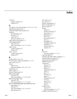
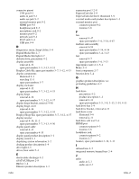
subwoofer location 2-9 removal 4-48 spare part number 3-4, 3-13, 4-48 switch cover removal 4-18 spare part number 3-3, 3-13, 4-18 system board removal 4-44 spare part numbers 3-4, 3-12, 3-14, 4-44 System Configuration menu, Setup Utility 5-4 system DMA specifications 6-5 system I/O address specifications 6-7 system information 5-3 backing up 8-2 performing a recovery 8-4 recovering 8-1 system interrupt specifications 6-6 system memory map specifications 6-6 T tools required 4-1 top components 2-1 top cover removal 4-38 spare part number 3-4, 3-13, 4-38 TouchPad 2-6 TouchPad button 2-6 TouchPad light 2-6 TouchPad on/off button 2-6 TouchPad on/off button board removal 4-42 spare part number 3-4, 3-13, 4-42 TouchPad scroll zone 2-6 treble scroll zone 2-3 treble/bass button 2-3 treble/bass down light 2-5 treble/bass up light 2-5 TV antenna/cable jack 2-7 TV tuner external antenna cable, spare part numbers 3-6, 3-11 TV tuner module removal 4-13 spare part numbers 3-6, 3-11, 4-13 TV tuner module cable, removal 4-53 TV tuner product description 1-3 U Universal Serial Bus (USB) board removal 4-51 spare part number 3-4, 3-13, 4-51 Universal Serial Bus (USB) port connector pinout 9-4 location 2-7, 2-8 unknown password 4-5 Index V vent 2-8, 2-9 volume down light 2-5 volume mute button 2-2 volume mute light 2-5 volume scroll zone 2-3 volume up light 2-5 W warranty period 3-1, 4-6 webcam location 2-1 product description 1-3 webcam light 2-1 webcam/microphone module removal 4-34 spare part number 3-7, 3-13, 4-34 webcam/microphone module cable, removal 4-35 Windows applications key 2-4 Windows logo key 2-4 wireless antennae disconnecting 4-17 locations 2-1 removal 4-33 spare part number 4-33 wireless button 2-3 wireless light 2-5 wireless product description 1-3 WLAN module removal 4-16 spare part numbers 3-6, 3-11, 4-16 WLAN module compartment 2-9 WLAN module compartment cover illustrated 3-9 removal 4-17 Index-5
-
 1
1 -
2
-
3
-
4
-
5
-
6
-
7
-
8
-
9
-
10
-
11
-
12
-
13
-
14
-
15
-
16
-
17
-
18
-
19
-
20
-
21
-
22
-
23
-
24
-
25
-
26
-
27
-
28
-
29
-
30
-
31
-
32
-
33
-
34
-
35
-
36
-
37
-
38
-
39
-
40
-
41
-
42
-
43
-
44
-
45
-
46
-
47
-
48
-
49
-
50
-
51
-
52
-
53
-
54
-
55
-
56
-
57
-
58
-
59
-
60
-
61
-
62
-
63
-
64
-
65
-
66
-
67
-
68
-
69
-
70
-
71
-
72
-
73
-
74
-
75
-
76
-
77
-
78
-
79
-
80
-
81
-
82
-
83
-
84
-
85
-
86
-
87
-
88
-
89
-
90
-
91
-
92
-
93
-
94
-
95
-
96
-
97
-
98
-
99
-
100
-
101
-
102
-
103
-
104
-
105
-
106
-
107
-
108
-
109
-
110
-
111
-
112
-
113
-
114
-
115
-
116
-
117
-
118
-
119
-
120
-
121
-
122
-
123
-
124
-
125
-
126
-
127
-
128
-
129
-
130
-
131
-
132
-
 133
133 -
 134
134 -
 135
135 -
 136
136 -
 137
137 -
 138
138
 |
 |