HP HDX18-1020US HP HDX 18 Entertainment PC - Maintenance and Service Guide - Page 64
Display assembly, Remove the display assembly
 |
UPC - 884420403616
View all HP HDX18-1020US manuals
Add to My Manuals
Save this manual to your list of manuals |
Page 64 highlights
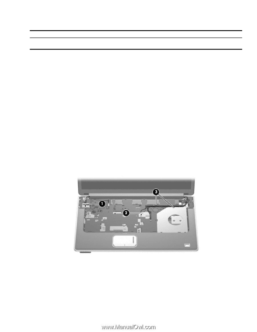
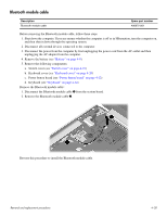
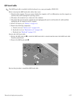
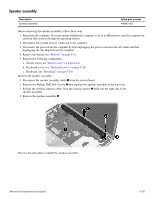
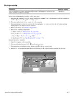
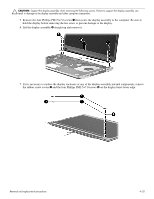
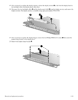
Display assembly Description 18.4-inch, AntiGlare, dual-lamp, display assembly (includes 2 WLAN antenna transceivers and cables, webcam, microphones, and logo) Spare part number 498166-001 Before removing the display assembly, follow these steps: 1. Shut down the computer. If you are unsure whether the computer is off or in Hibernation, turn the computer on, and then shut it down through the operating system. 2. Disconnect all external devices connected to the computer. 3. Disconnect the power from the computer by first unplugging the power cord from the AC outlet and then unplugging the AC adapter from the computer. 4. Remove the battery (see "Battery" on page 4-8). 5. Remove the following components: a. Switch cover (see "Switch cover" on page 4-18) b. Keyboard cover (see "Keyboard cover" on page 4-20) c. Keyboard (see "Keyboard" on page 4-24) d. Speaker assembly (see "Speaker assembly" on page 4-30) Remove the display assembly: 1. Open the computer as far as possible. 2. Disconnect the display panel cable 1 from the system board. 3. Disconnect the webcam/microphone module cable 2 from the system board. 4. Remove the WLAN antenna cable 3 from the opening and the routing channel built into the top cover. Removal and replacement procedures 4-31
-
 1
1 -
2
-
3
-
4
-
5
-
6
-
7
-
8
-
9
-
10
-
11
-
12
-
13
-
14
-
15
-
16
-
17
-
18
-
19
-
20
-
21
-
22
-
23
-
24
-
25
-
26
-
27
-
28
-
29
-
30
-
31
-
32
-
33
-
34
-
35
-
36
-
37
-
38
-
39
-
40
-
41
-
42
-
43
-
44
-
45
-
46
-
47
-
48
-
49
-
50
-
51
-
52
-
53
-
54
-
55
-
56
-
57
-
58
-
 59
59 -
 60
60 -
 61
61 -
 62
62 -
 63
63 -
 64
64 -
 65
65 -
 66
66 -
 67
67 -
 68
68 -
 69
69 -
70
-
71
-
72
-
73
-
74
-
75
-
76
-
77
-
78
-
79
-
80
-
81
-
82
-
83
-
84
-
85
-
86
-
87
-
88
-
89
-
90
-
91
-
92
-
93
-
94
-
95
-
96
-
97
-
98
-
99
-
100
-
101
-
102
-
103
-
104
-
105
-
106
-
107
-
108
-
109
-
110
-
111
-
112
-
113
-
114
-
115
-
116
-
117
-
118
-
119
-
120
-
121
-
122
-
123
-
124
-
125
-
126
-
127
-
128
-
129
-
130
-
131
-
132
-
133
-
134
-
135
-
136
-
137
-
138
 |
 |