HP J9028B User Manual - Page 13
Prepare the Installation Site, Cautions
 |
View all HP J9028B manuals
Add to My Manuals
Save this manual to your list of manuals |
Page 13 highlights
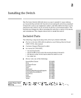
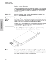
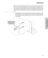
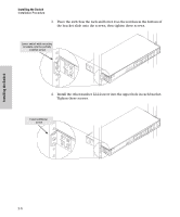
Installing the Switch Cautions Installing the Switch Installation Procedure Installation Precautions (Continued) ■ Ensure the power source circuits are properly grounded, then use the power cord supplied with the switch to connect it to the power source. ■ If your installation requires a different power cord than the one supplied with the switch, be sure to use a power cord displaying the mark of the safety agency that defines the regulations for power cords in your country. The mark is your assurance that the power cord can be used safely with the switch. ■ When installing the switch, the AC outlet should be near the switch and should be easily accessible in case the switch must be powered off. ■ Ensure the switch does not overload the power circuits, wiring, and overcurrent protection. To determine the possibility of overloading the supply circuits, add together the ampere ratings of all devices installed on the same circuit as the switch and compare the total with the rating limit for the circuit. The maximum ampere ratings are usually printed on the devices near the AC power connectors. ■ Do not install the switch in an environment where the operating ambient temperature might exceed 40 °C (104 °F). ■ Ensure the air flow around the sides and back of the switch is not restricted. 1. Prepare the Installation Site Be sure to follow the guidelines below to ensure proper operation when installing the switch into a network: ■ Ethernet cable type: Unshielded twisted pair (UTP) or shielded twisted pair (STP) cables with RJ-45 connectors, maximum length 100 meters (328 ft); Category 3 or better for 10Base-T, Category 5 or better for 100Base-TX, and Category 5, 5e, or 6 for 1000Base-T. ■ Fiber cable type: For 1000Base-SX mini-GBIC, 62.5/125 µm or 50/125 µm core/cladding diameter, graded-index, multimode fiber-optic cables that are fitted with LC connectors. For 1000Base-LX and 1000Base-LH miniGBICs, single-mode cables fitted with LC connectors. ■ Protect the switch from radio frequency interference emissions. ■ Use electrical surge suppression. ■ Use safe connections with no damaged cables, connectors or shields. 2-3
-
 1
1 -
2
-
3
-
4
-
5
-
6
-
7
-
 8
8 -
 9
9 -
 10
10 -
 11
11 -
 12
12 -
 13
13 -
 14
14 -
 15
15 -
 16
16 -
 17
17 -
 18
18 -
19
-
20
-
21
-
22
-
23
-
24
-
25
-
26
-
27
-
28
-
29
-
30
-
31
-
32
-
33
-
34
-
35
-
36
-
37
-
38
-
39
-
40
-
41
-
42
-
43
-
44
-
45
-
46
-
47
-
48
-
49
-
50
 |
 |