HP J9028B User Manual - Page 14
Installation Space Requirements, 2. Verify the Switch Passes Self Test
 |
View all HP J9028B manuals
Add to My Manuals
Save this manual to your list of manuals |
Page 14 highlights
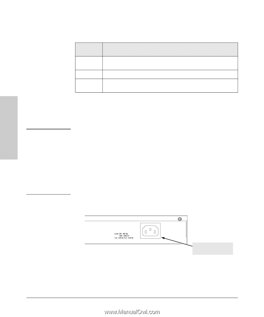
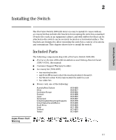
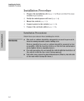
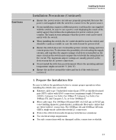
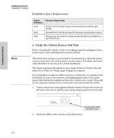
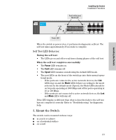
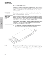
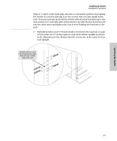
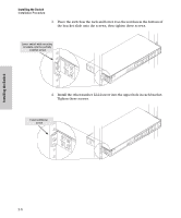
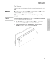
Installing the Switch Installing the Switch Installation Procedure Installation Space Requirements Switch Orientation Front Back Sides Clearance Requirements At least 7.6 cm (3 inches) of space for the twisted-pair and fiber-optic cabling. At least 3.8 cm (1 1/2 inches) of space for the power cord and switch cooling. At least 7.6 cm (3 inches) for cooling, except if the switch is installed in an open EIA/TIA rack. Note 2. Verify the Switch Passes Self Test Before mounting the switch, verify it is working properly by plugging it into a power source and confirming that it passes self test. The switch does not have a power switch. It is powered on when the power cord is connected to the switch and to a power source. For safety, the power outlet should be located near the switch installation. The switch automatically adjusts to any voltage between 100-240 volts and either 50 or 60 Hz. No voltage range settings are required. If your installation requires a different power cord than the one supplied with the switch, be sure to use a power cord displaying the mark of the safety agency that defines the regulations for power cords in your country. The mark is your assurance that the power cord can be used safely with the switch. 1. Connect the power cord supplied with the switch to the power socket on the back of the switch, and then into a properly grounded electrical outlet. Connect power cord to the power socket 2. Check the LEDs on the switch as described below. 2-4
-
 1
1 -
2
-
3
-
4
-
5
-
6
-
7
-
8
-
 9
9 -
 10
10 -
 11
11 -
 12
12 -
 13
13 -
 14
14 -
 15
15 -
 16
16 -
 17
17 -
 18
18 -
 19
19 -
20
-
21
-
22
-
23
-
24
-
25
-
26
-
27
-
28
-
29
-
30
-
31
-
32
-
33
-
34
-
35
-
36
-
37
-
38
-
39
-
40
-
41
-
42
-
43
-
44
-
45
-
46
-
47
-
48
-
49
-
50
 |
 |