HP J9028B User Manual - Page 19
Wall Mounting, WARNING, Caution
 |
View all HP J9028B manuals
Add to My Manuals
Save this manual to your list of manuals |
Page 19 highlights
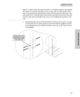
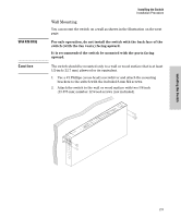
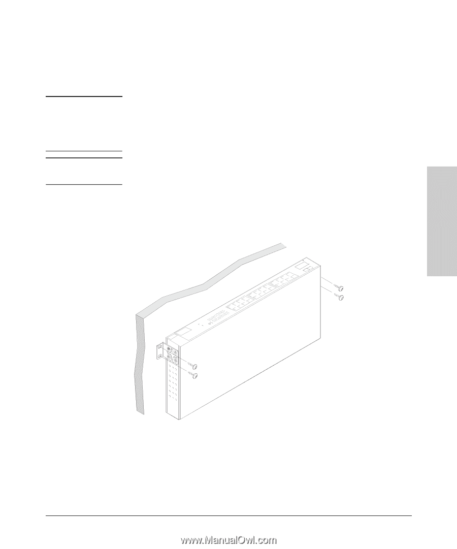
WARNING Caution Installing the Switch Installation Procedure Wall Mounting You can mount the switch on a wall as shown in the illustration on the next page. For safe operation, do not install the switch with the back face of the switch (with the fan vents) facing upward. It is recommended the switch be mounted with the ports facing upward. The switch should be mounted only to a wall or wood surface that is at least 1/2-inch (12.7 mm) plywood or its equivalent. 1. Use a #1 Phillips (cross-head) screwdriver and attach the mounting brackets to the switch with the included 8-mm M4 screws. 2. Attach the switch to the wall or wood surface with two 5/8-inch (15.875 mm) number 12 wood screws (not included). Installing the Switch 2-9
-
 1
1 -
2
-
3
-
4
-
5
-
6
-
7
-
8
-
9
-
10
-
11
-
12
-
13
-
 14
14 -
 15
15 -
 16
16 -
 17
17 -
 18
18 -
 19
19 -
 20
20 -
 21
21 -
 22
22 -
 23
23 -
 24
24 -
25
-
26
-
27
-
28
-
29
-
30
-
31
-
32
-
33
-
34
-
35
-
36
-
37
-
38
-
39
-
40
-
41
-
42
-
43
-
44
-
45
-
46
-
47
-
48
-
49
-
50
 |
 |
2-9
Installing the Switch
Installation Procedure
Installing the Switch
Wall Mounting
You can mount the switch on a wall as shown in the illustration on the next
page.
WARNING
For safe operation, do not install the switch with the back face of the
switch (with the fan vents) facing upward.
It is recommended the switch be mounted with the ports facing
upward.
Caution
The switch should be mounted only to a wall or wood surface that is at least
1/2-inch (12.7 mm) plywood or its equivalent.
1.
Use a #1 Phillips (cross-head) screwdriver and attach the mounting
brackets to the switch with the included 8-mm M4 screws.
2.
Attach the switch to the wall or wood surface with two 5/8-inch
(15.875 mm) number 12 wood screws (not included).