HP J9028B User Manual - Page 20
Horizontal Surface Mounting, 4. Connect the Switch to a Power Source, 5. Connect the Network Cables
 |
View all HP J9028B manuals
Add to My Manuals
Save this manual to your list of manuals |
Page 20 highlights
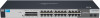
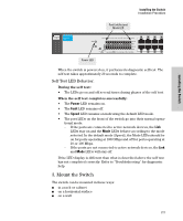
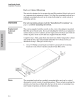
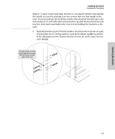
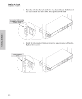
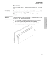
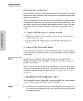
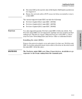
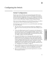
Installing the Switch Installing the Switch Installation Procedure Horizontal Surface Mounting Place the switch on a table or other horizontal surface. The switch comes with rubber feet in the accessory kit that can be used to help keep the switch from sliding on the surface. Attach the rubber feet to the four corners on the bottom of the switch within the embossed angled lines. Use a sturdy surface in an uncluttered area. You may want to secure the networking cables and switch power cord to the table leg or other part of the surface structure to help prevent tripping over the cords. 4. Connect the Switch to a Power Source 1.) Plug the included power cord into the switch's power socket and into a nearby AC power source. 2.) Re-check the LEDs during self test. See "Self Test LED Behavior" on page 2-5. 5. Connect the Network Cables Connect the network cables, from the network devices or your patch panels, to the fixed RJ-45 ports on the switch or to any mini-GBICs you have installed in the switch. Note Each of the two mini-GBIC slots is shared with the associated 10/100/ 1000Base-T RJ-45 port. If a mini-GBIC is installed in a slot, the associated RJ-45 port is disabled. When a network cable from an active network device is connected to the port, the port LED for that port should go on. If the port LED does not go on when the network cable is connected to the port, see "Diagnosing with the LEDs" on page 4-2. 6. Installing or Removing mini-GBICs You can install or remove a mini-GBIC from a mini-GBIC slot without having to power off the switch. Use only ProCurve mini-GBICs. Note ■ The mini-GBIC slots are shared with 10/100/1000Base-T RJ-45 ports 23 and 24. If a mini-GBIC is installed in a slot, the associated RJ-45 port is disabled and cannot be used. 2-10
-
 1
1 -
2
-
3
-
4
-
5
-
6
-
7
-
8
-
9
-
10
-
11
-
12
-
13
-
14
-
 15
15 -
 16
16 -
 17
17 -
 18
18 -
 19
19 -
 20
20 -
 21
21 -
 22
22 -
 23
23 -
 24
24 -
 25
25 -
26
-
27
-
28
-
29
-
30
-
31
-
32
-
33
-
34
-
35
-
36
-
37
-
38
-
39
-
40
-
41
-
42
-
43
-
44
-
45
-
46
-
47
-
48
-
49
-
50
 |
 |