HP J9028B User Manual - Page 8
LEDs, LED Mode Select Button and Indicator LEDs, switch panel - reset
 |
View all HP J9028B manuals
Add to My Manuals
Save this manual to your list of manuals |
Page 8 highlights
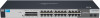
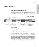
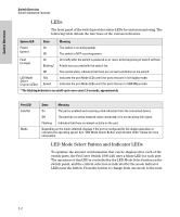
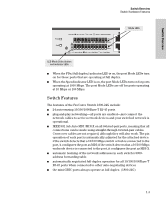
Switch Overview Switch Overview Switch Hardware Features LEDs The front panel of the switch provides status LEDs for system monitoring. The following table details the functions of the various indicators. System LED State Meaning Power (green) On The switch is receiving power. Off The switch is NOT receiving power. Fault (orange) On Blinking* On briefly after the switch is powered on or reset, at the beginning of switch self test. A fault has occurred with the switch fan. Off The normal state; indicates that there are no fault conditions on the switch. LED Mode Select (2 green LEDs) FDx Speed Indicates the port Mode LEDs are lit for ports that are in full-duplex mode. Indicates the port Mode LEDs are lit for ports that are in 1000 Mbps mode. * The blinking behavior is an on/off cycle once every 1.6 seconds, approximately. Port LED Link/Act Mode State Meaning On The port is enabled and receiving a link indication from the connected device. Off The port has no active network cable connected, or is not receiving link signal. Flashing Indicates that there is network activity on the port. Depending on the mode selected, displays if the port is configured for full-duplex operation or indicates the operating speed. See "LED Mode Select Button and Indicator LEDs" below for more information. LED Mode Select Button and Indicator LEDs To optimize the amount of information that can be displayed for each of the switch ports, the ProCurve Switch 1800-24G uses a Mode LED for each port. The operation of this LED is controlled by the LED Mode Select button on the switch panel, and the current selection is indicated by the mode indicator LEDs near the button. Press the button to change from one mode to the next. 1-2
-
 1
1 -
2
-
 3
3 -
 4
4 -
 5
5 -
 6
6 -
 7
7 -
 8
8 -
 9
9 -
 10
10 -
 11
11 -
 12
12 -
 13
13 -
14
-
15
-
16
-
17
-
18
-
19
-
20
-
21
-
22
-
23
-
24
-
25
-
26
-
27
-
28
-
29
-
30
-
31
-
32
-
33
-
34
-
35
-
36
-
37
-
38
-
39
-
40
-
41
-
42
-
43
-
44
-
45
-
46
-
47
-
48
-
49
-
50
 |
 |
