HP J9650A User Manual - Page 3
Installation - power injector
 |
View all HP J9650A manuals
Add to My Manuals
Save this manual to your list of manuals |
Page 3 highlights
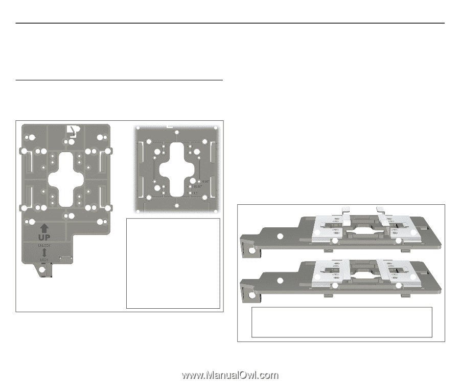
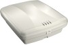
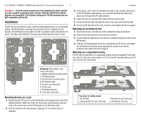
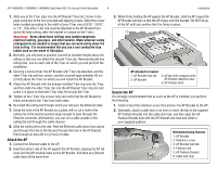
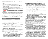
HP E-MSM430, E-MSM460, E-MSM466 Dual Radio 802.11n Access Points Quickstart 3 Installation Caution: If the AP will be powered by a user-supplied PoE power injector, use only a gigabit-compatible power injector. Although 10/100 PoE-enabled switches are compatible, PoE injectors designed for 10/100 networks only are NOT compatible with the AP. Installation The AP can be mounted on a wall, a wall-mounted electrical box, or a suspended ceiling. The AP Bracket is mounted first and then the AP is attached to the bracket. The AP Bracket is two-sided: The AP is installed on the side with the UP arrow. The other side with the T-bar clip screw holes faces the wall or T-bar. ➀ ➃➄ ➁ ➂ ➀ ➄➃ ➇ ➇ ➅ ➅ ➇ ➇ ➃➄ ➀ ➆ ➄➃ ➂ ➀ AP Bracket (AP side left, wall/ ceiling side right) 1: Adapter Bracket mounting holes 2: AP Bracket latch 3: Electrical box mounting holes 4: AP retention tabs 5: Drywall mounting holes 6: Cutout area 7: AP Bracket lock tab 8: T-bar clip screw holes Mounting directly on a wall 1. Respecting the UP arrow on the AP Bracket, hold it against the wall at the desired position. Mark two holes for the screws (wall anchors) and one hole in the cutout area of the AP Bracket for the Ethernet cable. 2. Drill two holes for the wall anchors, typically 4.7 mm (3/16 inch) in diameter. 3. If necessary, drill a hole for the Ethernet cable in the marked cutout area of the AP Bracket. Alternatively, you can feed the Ethernet cable from above and through the AP cable channel. 4. Insert the anchors and tap them flush with the wall surface. 5. Pull the Ethernet cable through the hole in the wall and the AP Bracket. 6. Screw the AP Bracket to the wall. Continue with Attach the AP on page 4. Mounting on an electrical box 1. Disconnect power and take any other needed security precautions. 2. Remove the electrical box cover and any contents. 3. Pull the Ethernet cable down into the box and then through the hole in the AP Bracket. 4. Hold the AP Bracket against the box respecting the UP arrow, and attach the AP Bracket to the box using appropriate countersunk screws. Continue with Attach the AP on page 4. Mounting on a suspended ceiling The AP can be mounted on a suspended ceiling using the supplied T-bar clips. Two sets of T-bar clips are provided, a 12.5 mm set for recessed tiles and a 4.5 mm set for flush-mount tiles. ➀ ➁ ➃ ➁ ➃ ➀ ➂ ➃ ➂ ➃ T-bar clips for ceiling mount 1: AP Bracket 2: Recessed tile 12.5 mm T-bar clip 3: Flat tile 4.5 mm T-bar clip 4: AP Bracket T-bar slot
-
 1
1 -
 2
2 -
 3
3 -
 4
4 -
 5
5 -
 6
6 -
 7
7 -
 8
8
 |
 |