HP J9650A User Manual - Page 4
Attach the AP, Secure the AP - access point
 |
View all HP J9650A manuals
Add to My Manuals
Save this manual to your list of manuals |
Page 4 highlights
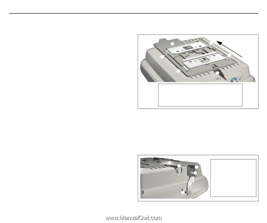
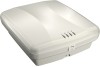
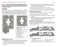
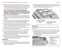
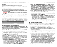
HP E-MSM430, E-MSM460, E-MSM466 Dual Radio 802.11n Access Points Quickstart 4 Installation 1. Slide one of the T-bar clips into the AP Bracket T-bar slot. Screw it into place using two of the four provided self-tapping screws. Select the screw holes marked according to the width of your T-bar, one of 9/16", 15/16", or 1.5". (The other T-bar clip must be attached to the AP Bracket from above the false ceiling, after the bracket is in place on the T-bar.) Warning: Areas above false ceilings may contain dangerous electrical cabling, gas pipes, and other hazards. Make whatever safety arrangements are needed to ensure that you can work safely above the false ceiling. It is recommended that you use a non-conductive step ladder such as one made of fiberglass. 2. Normally, you will need to position yourself at shoulder-height above the ceiling so that you can attach the second T-bar clip. Remove/relocate two ceiling tiles, one on each side of the T-bar on which you will perform the installation. 3. Carrying a screw driver, the AP Bracket with T-bar clip attached, and the other T-bar clip and two screws, position yourself approximately 60 cm (2 feet) above the T-bar on which you will install the AP Bracket. 4. Attach the AP Bracket with the already-installed T-bar clip onto the T-bar, and then slide the other T-bar clip into the AP Bracket T-bar clip slot and screw it in place so that both T-bar clips firmly grip the T-bar. 5. Tighten all four T-bar clip screws fully and verify that the AP Bracket is firmly anchored to the T-bar from both sides. 6. Re-install the ceiling tile through which you will pass the Ethernet cable. 7. Using the hole in the AP Bracket as a guide, drill or cut a hole in the ceiling tile at the desired position large enough to pass through the Ethernet connector. Alternatively, you can run a cable outside of the ceiling tile and through the cable channel. 8. Slide the ceiling tile to the side. Feed the Ethernet cable down from above and through the hole in the tile and through the hole in the AP Bracket. Pull through an extra 60 cm (2 feet) of cable. Attach the AP 1. Connect the Ethernet cable to the AP. 2. Hold the bottom side of the AP against the AP Bracket, aligning the AP tab slots with the AP retention tabs on the AP Bracket. Pull back any Ethernet cable slack at the same time. 3. While firmly holding the AP against the AP Bracket, slide the AP toward the AP Bracket lock tab so that the AP snaps onto the bracket. DO NOT let go of the AP until you confirm that it is firmly in place. ➀ ➁ ➂ ➂ ➂ ➂ ➃ AP attached to bracket 1: AP Bracket lock tab 2: AP Bracket 3: AP tab slots snapped onto AP Bracket retention tabs 4: AP Bracket latch Secure the AP It is strongly recommended that as soon as the AP is installed, you perform the following. 1. Install at least the retention screw that anchors the AP Bracket to the AP. 2. Optionally, attach a cable lock in its hole or Insert the tab of the supplied AP Padlock Bracket into the cable lock hole, and then align the AP Padlock Bracket hole with the AP Bracket lock hole and install a user-supplied padlock. ➀➁ ➂ ➃ ➄ ➅ Retention/locking features 1: AP Bracket 2: Retention screw 3: AP Bracket lock tab 4: Padlock hole 5: AP Padlock Bracket 6: Cable lock hole
-
 1
1 -
 2
2 -
 3
3 -
 4
4 -
 5
5 -
 6
6 -
 7
7 -
 8
8
 |
 |