HP LaserJet 9040/9050 Service Manual - Page 100
Image formation system, The eight processes of image formation
 |
View all HP LaserJet 9040/9050 manuals
Add to My Manuals
Save this manual to your list of manuals |
Page 100 highlights
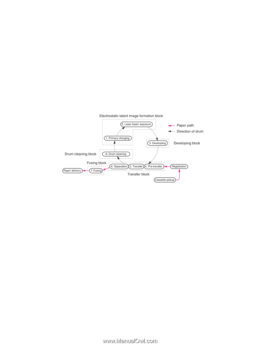
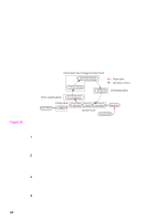
Image formation system The image formation system consists of the cartridge, transfer charging roller, and fuser. When a print command is sent from the formatter, the engine controller drives the main motor to rotate the photosensitive drum, primary charging roller, developing cylinder, transfer charging roller, and pressure roller. The primary charging roller applies a uniform negative charge to the photosensitive drum surface. Laser beams, modulated by the signals from the formatter, focus on the photosensitive drum surface to form a latent image on the photosensitive drum. Toner on the developing cylinder develops the latent image formed on the photosensitive drum into a visible image, which is transferred onto media by the transfer charging roller. The toner transferred is changed to a permanent image by heat and pressure in the fuser. The cleaning blade scrapes residual toner from the photosensitive drum, and the primary charging roller applies a uniform negative charge to the photosensitive drum surface in preparation for the next latent image. Figure 29. Image formation The eight processes of image formation 1 Conditioning (primary charging)-Consists of the application of a uniform negative charge to the surface of the drum with the primary charging roller located in the print cartridge. The primary charging roller is made of conductive rubber. An ac bias is applied to the roller to erase any residual charges from any previous image. A negative dc bias is applied by the charging roller to create a uniform negative potential on the drum surface. 2 Writing (laser beam exposure)-Two laser diodes project laser beams onto a rotating scanning mirror. As the mirror rotates, the beams reflect off the mirror, first through a set of focusing lenses, then off a mirror, and finally through a slot in the top of the print cartridge, and onto the photosensitive drum. The twin beams sweep the drum from left to right, discharging the negative potential wherever the beams strike the surface. This creates a latent electrostatic image, which later is developed into a visible image. 3 Developing-At this stage of the process, the latent electrostatic image is present on the drum. The toner particles obtain a negative surface charge by rubbing against the developing cylinder which is connected to a negative dc supply. The negatively charged toner is attracted to the discharged (exposed, grounded) areas of the drum, and is repelled from the negatively charged (unexposed) areas. 4 Pre-transfer-Applies bias to prevent toner on the photosensitive drum from adhering to the pre-transfer upper guide. 84 Chapter 5 Theory of operation
-
 1
1 -
2
-
3
-
4
-
5
-
6
-
7
-
8
-
9
-
10
-
11
-
12
-
13
-
14
-
15
-
16
-
17
-
18
-
19
-
20
-
21
-
22
-
23
-
24
-
25
-
26
-
27
-
28
-
29
-
30
-
31
-
32
-
33
-
34
-
35
-
36
-
37
-
38
-
39
-
40
-
41
-
42
-
43
-
44
-
45
-
46
-
47
-
48
-
49
-
50
-
51
-
52
-
53
-
54
-
55
-
56
-
57
-
58
-
59
-
60
-
61
-
62
-
63
-
64
-
65
-
66
-
67
-
68
-
69
-
70
-
71
-
72
-
73
-
74
-
75
-
76
-
77
-
78
-
79
-
80
-
81
-
82
-
83
-
84
-
85
-
86
-
87
-
88
-
89
-
90
-
91
-
92
-
93
-
94
-
 95
95 -
 96
96 -
 97
97 -
 98
98 -
 99
99 -
 100
100 -
 101
101 -
 102
102 -
 103
103 -
 104
104 -
 105
105 -
106
-
107
-
108
-
109
-
110
-
111
-
112
-
113
-
114
-
115
-
116
-
117
-
118
-
119
-
120
-
121
-
122
-
123
-
124
-
125
-
126
-
127
-
128
-
129
-
130
-
131
-
132
-
133
-
134
-
135
-
136
-
137
-
138
-
139
-
140
-
141
-
142
-
143
-
144
-
145
-
146
-
147
-
148
-
149
-
150
-
151
-
152
-
153
-
154
-
155
-
156
-
157
-
158
-
159
-
160
-
161
-
162
-
163
-
164
-
165
-
166
-
167
-
168
-
169
-
170
-
171
-
172
-
173
-
174
-
175
-
176
-
177
-
178
-
179
-
180
-
181
-
182
-
183
-
184
-
185
-
186
-
187
-
188
-
189
-
190
-
191
-
192
-
193
-
194
-
195
-
196
-
197
-
198
-
199
-
200
-
201
-
202
-
203
-
204
-
205
-
206
-
207
-
208
-
209
-
210
-
211
-
212
-
213
-
214
-
215
-
216
-
217
-
218
-
219
-
220
-
221
-
222
-
223
-
224
-
225
-
226
-
227
-
228
-
229
-
230
-
231
-
232
-
233
-
234
-
235
-
236
-
237
-
238
-
239
-
240
-
241
-
242
-
243
-
244
-
245
-
246
-
247
-
248
-
249
-
250
-
251
-
252
-
253
-
254
-
255
-
256
-
257
-
258
-
259
-
260
-
261
-
262
-
263
-
264
-
265
-
266
-
267
-
268
-
269
-
270
-
271
-
272
-
273
-
274
-
275
-
276
-
277
-
278
-
279
-
280
-
281
-
282
-
283
-
284
-
285
-
286
-
287
-
288
-
289
-
290
-
291
-
292
-
293
-
294
-
295
-
296
-
297
-
298
-
299
-
300
-
301
-
302
-
303
-
304
-
305
-
306
-
307
-
308
-
309
-
310
-
311
-
312
-
313
-
314
-
315
-
316
-
317
-
318
-
319
-
320
-
321
-
322
-
323
-
324
-
325
-
326
-
327
-
328
-
329
-
330
-
331
-
332
 |
 |