HP LaserJet 9040/9050 Service Manual - Page 101
Print cartridge, Cartridge design, No-shake toner
 |
View all HP LaserJet 9040/9050 manuals
Add to My Manuals
Save this manual to your list of manuals |
Page 101 highlights
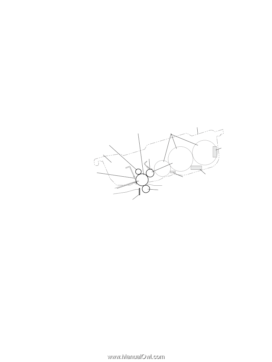
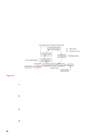
5 Transfer-During the transfer process, the toner image on the drum surface is transferred to the paper. The transfer charging roller applies a positive charge to the back of the paper and causes the negatively charged toner on the drum surface to be attracted to the paper. After separation, the drum is cleaned and conditioned for the next image. 6 Separation-During the separating process, the paper separates from the drum. To stabilize the feed system and to prevent dropouts on the printed image at low temperature and humidity, the charge on the back of the paper is reduced by the static charge eliminator. 7 Fusing-During the fusing process, the toner is fused to the paper by heat and pressure to produce a permanent image. The paper passes between a heated fuser element and a soft pressure roller. This melts the toner and presses it into the paper. 8 Drum cleaning-The cleaning blade is in contact with the surface of the drum at all times. As the drum rotates during printing, excess toner is scraped off and stored in the waste toner receptacle. Print cartridge Figure 30. Laser beams Cartridge Toner reservoirs Primary charging roller Waste toner reservoir Cleaner blade Photosensitive drum roller Blade Developing cylinder Cartridge memory Flat antenna Plate antenna Pre-transfer guide Transfer charging roller Static charge eliminator Print cartridge Cartridge design The design of the print cartridge incorporates dramatic changes in the toner hopper geometry and stirrer design. The cartridge contains three main interconnecting toner reservoir areas, each with a cylindrical shape. A cylindrically shaped hopper effectively eliminates the packing and accumulation of toner in areas where it will not reach the development area. Another key improvement was realized in the design of the toner stirrer, where stirrers rotating within each of the hopper cylinders unpack the toner, allowing it to be displaced easily into the cartridge development area. No-shake toner Shaking is not required at installation or at the end of cartridge life because the geometry of the hopper and stirrer design automatically redistributes and unpacks the toner. The overall design of the "no-shake" system is so efficient that when fading occurs for the first time, it is a sure indication that the cartridge is out of toner. Shaking the cartridge will not produce more toner for printing. Image formation system 85
-
 1
1 -
2
-
3
-
4
-
5
-
6
-
7
-
8
-
9
-
10
-
11
-
12
-
13
-
14
-
15
-
16
-
17
-
18
-
19
-
20
-
21
-
22
-
23
-
24
-
25
-
26
-
27
-
28
-
29
-
30
-
31
-
32
-
33
-
34
-
35
-
36
-
37
-
38
-
39
-
40
-
41
-
42
-
43
-
44
-
45
-
46
-
47
-
48
-
49
-
50
-
51
-
52
-
53
-
54
-
55
-
56
-
57
-
58
-
59
-
60
-
61
-
62
-
63
-
64
-
65
-
66
-
67
-
68
-
69
-
70
-
71
-
72
-
73
-
74
-
75
-
76
-
77
-
78
-
79
-
80
-
81
-
82
-
83
-
84
-
85
-
86
-
87
-
88
-
89
-
90
-
91
-
92
-
93
-
94
-
95
-
 96
96 -
 97
97 -
 98
98 -
 99
99 -
 100
100 -
 101
101 -
 102
102 -
 103
103 -
 104
104 -
 105
105 -
 106
106 -
107
-
108
-
109
-
110
-
111
-
112
-
113
-
114
-
115
-
116
-
117
-
118
-
119
-
120
-
121
-
122
-
123
-
124
-
125
-
126
-
127
-
128
-
129
-
130
-
131
-
132
-
133
-
134
-
135
-
136
-
137
-
138
-
139
-
140
-
141
-
142
-
143
-
144
-
145
-
146
-
147
-
148
-
149
-
150
-
151
-
152
-
153
-
154
-
155
-
156
-
157
-
158
-
159
-
160
-
161
-
162
-
163
-
164
-
165
-
166
-
167
-
168
-
169
-
170
-
171
-
172
-
173
-
174
-
175
-
176
-
177
-
178
-
179
-
180
-
181
-
182
-
183
-
184
-
185
-
186
-
187
-
188
-
189
-
190
-
191
-
192
-
193
-
194
-
195
-
196
-
197
-
198
-
199
-
200
-
201
-
202
-
203
-
204
-
205
-
206
-
207
-
208
-
209
-
210
-
211
-
212
-
213
-
214
-
215
-
216
-
217
-
218
-
219
-
220
-
221
-
222
-
223
-
224
-
225
-
226
-
227
-
228
-
229
-
230
-
231
-
232
-
233
-
234
-
235
-
236
-
237
-
238
-
239
-
240
-
241
-
242
-
243
-
244
-
245
-
246
-
247
-
248
-
249
-
250
-
251
-
252
-
253
-
254
-
255
-
256
-
257
-
258
-
259
-
260
-
261
-
262
-
263
-
264
-
265
-
266
-
267
-
268
-
269
-
270
-
271
-
272
-
273
-
274
-
275
-
276
-
277
-
278
-
279
-
280
-
281
-
282
-
283
-
284
-
285
-
286
-
287
-
288
-
289
-
290
-
291
-
292
-
293
-
294
-
295
-
296
-
297
-
298
-
299
-
300
-
301
-
302
-
303
-
304
-
305
-
306
-
307
-
308
-
309
-
310
-
311
-
312
-
313
-
314
-
315
-
316
-
317
-
318
-
319
-
320
-
321
-
322
-
323
-
324
-
325
-
326
-
327
-
328
-
329
-
330
-
331
-
332
 |
 |