HP LaserJet 9040/9050 Service Manual - Page 167
Orientation, Left side cover,
 |
View all HP LaserJet 9040/9050 manuals
Add to My Manuals
Save this manual to your list of manuals |
Page 167 highlights
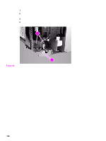
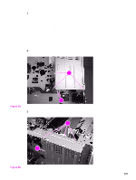
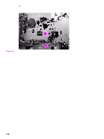
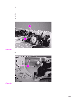
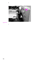
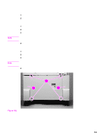
Tray 4 The following covers and assemblies can be removed from tray 4: z Left side cover z Right side cover z Back covers z Tray assembly z Tray 4 rollers (pickup, feed, and separation) z Registration assembly z Drive motor z Drive assembly z Controller board z Paper-size detection switch PCB z Power supply z Pickup assembly z Paper connecting unit Orientation See "Orientation of the printer (with tray 4)" on page 100. Left side cover 1 Remove two screws (callout 1) from the left side cover. 2 Pull the top edge of the cover outward. 3 Lift the left side cover up and outward to remove it from tray 4. 21 2 Figure 101. Left side cover To reinstall Make sure that the hook (callout 2) on the inside of the cover connects correctly. Tray 4 151
-
 1
1 -
2
-
3
-
4
-
5
-
6
-
7
-
8
-
9
-
10
-
11
-
12
-
13
-
14
-
15
-
16
-
17
-
18
-
19
-
20
-
21
-
22
-
23
-
24
-
25
-
26
-
27
-
28
-
29
-
30
-
31
-
32
-
33
-
34
-
35
-
36
-
37
-
38
-
39
-
40
-
41
-
42
-
43
-
44
-
45
-
46
-
47
-
48
-
49
-
50
-
51
-
52
-
53
-
54
-
55
-
56
-
57
-
58
-
59
-
60
-
61
-
62
-
63
-
64
-
65
-
66
-
67
-
68
-
69
-
70
-
71
-
72
-
73
-
74
-
75
-
76
-
77
-
78
-
79
-
80
-
81
-
82
-
83
-
84
-
85
-
86
-
87
-
88
-
89
-
90
-
91
-
92
-
93
-
94
-
95
-
96
-
97
-
98
-
99
-
100
-
101
-
102
-
103
-
104
-
105
-
106
-
107
-
108
-
109
-
110
-
111
-
112
-
113
-
114
-
115
-
116
-
117
-
118
-
119
-
120
-
121
-
122
-
123
-
124
-
125
-
126
-
127
-
128
-
129
-
130
-
131
-
132
-
133
-
134
-
135
-
136
-
137
-
138
-
139
-
140
-
141
-
142
-
143
-
144
-
145
-
146
-
147
-
148
-
149
-
150
-
151
-
152
-
153
-
154
-
155
-
156
-
157
-
158
-
159
-
160
-
161
-
 162
162 -
 163
163 -
 164
164 -
 165
165 -
 166
166 -
 167
167 -
 168
168 -
 169
169 -
 170
170 -
 171
171 -
 172
172 -
173
-
174
-
175
-
176
-
177
-
178
-
179
-
180
-
181
-
182
-
183
-
184
-
185
-
186
-
187
-
188
-
189
-
190
-
191
-
192
-
193
-
194
-
195
-
196
-
197
-
198
-
199
-
200
-
201
-
202
-
203
-
204
-
205
-
206
-
207
-
208
-
209
-
210
-
211
-
212
-
213
-
214
-
215
-
216
-
217
-
218
-
219
-
220
-
221
-
222
-
223
-
224
-
225
-
226
-
227
-
228
-
229
-
230
-
231
-
232
-
233
-
234
-
235
-
236
-
237
-
238
-
239
-
240
-
241
-
242
-
243
-
244
-
245
-
246
-
247
-
248
-
249
-
250
-
251
-
252
-
253
-
254
-
255
-
256
-
257
-
258
-
259
-
260
-
261
-
262
-
263
-
264
-
265
-
266
-
267
-
268
-
269
-
270
-
271
-
272
-
273
-
274
-
275
-
276
-
277
-
278
-
279
-
280
-
281
-
282
-
283
-
284
-
285
-
286
-
287
-
288
-
289
-
290
-
291
-
292
-
293
-
294
-
295
-
296
-
297
-
298
-
299
-
300
-
301
-
302
-
303
-
304
-
305
-
306
-
307
-
308
-
309
-
310
-
311
-
312
-
313
-
314
-
315
-
316
-
317
-
318
-
319
-
320
-
321
-
322
-
323
-
324
-
325
-
326
-
327
-
328
-
329
-
330
-
331
-
332
 |
 |
Tray 4
151
Tray 4
The following covers and assemblies can be removed from tray 4:
Orientation
See "Orientation of the printer (with tray 4)" on page 100.
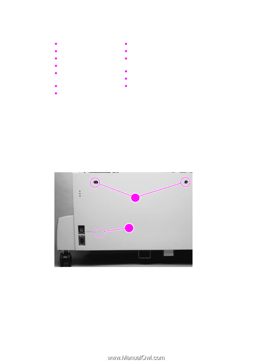
Left side cover
1
Remove two screws (callout 1) from the left side cover.
2
Pull the top edge of the cover outward.
3
Lift the left side cover up and outward to remove it from tray 4.
Figure 101.
Left side cover
To reinstall
Make sure that the hook (callout 2) on the inside of the cover connects correctly.
Left side cover
Right side cover
Back covers
Tray assembly
Tray 4 rollers (pickup, feed,
and separation)
Registration assembly
Drive motor
Drive assembly
Controller board
Paper-size detection switch
PCB
Power supply
Pickup assembly
Paper connecting unit
2
2
2
1