HP LaserJet 9040/9050 Service Manual - Page 172
CAUTION, If you cannot reach the three cable connectors
 |
View all HP LaserJet 9040/9050 manuals
Add to My Manuals
Save this manual to your list of manuals |
Page 172 highlights
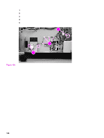
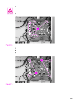
CAUTION Note Registration assembly 1 Remove the right side cover. See page 152. 2 Remove four screws (callout 1). Use care when following step 3. Three cables are connected to the registration assembly. 3 Gently lift the registration assembly off of tray 4, and unplug three connectors (callout 2) from the rear of the registration assembly. If you cannot reach the three cable connectors, remove the center back cover (page 153), remove the right back cover (page 153), and unplug the connectors (figure 107, callout 3) from the back of tray 4. 12 2 Figure 106. Registration assembly (1 of 2) 32 Figure 107. Registration assembly (2 of 2) 156 Chapter 6 Removal and replacement
-
 1
1 -
2
-
3
-
4
-
5
-
6
-
7
-
8
-
9
-
10
-
11
-
12
-
13
-
14
-
15
-
16
-
17
-
18
-
19
-
20
-
21
-
22
-
23
-
24
-
25
-
26
-
27
-
28
-
29
-
30
-
31
-
32
-
33
-
34
-
35
-
36
-
37
-
38
-
39
-
40
-
41
-
42
-
43
-
44
-
45
-
46
-
47
-
48
-
49
-
50
-
51
-
52
-
53
-
54
-
55
-
56
-
57
-
58
-
59
-
60
-
61
-
62
-
63
-
64
-
65
-
66
-
67
-
68
-
69
-
70
-
71
-
72
-
73
-
74
-
75
-
76
-
77
-
78
-
79
-
80
-
81
-
82
-
83
-
84
-
85
-
86
-
87
-
88
-
89
-
90
-
91
-
92
-
93
-
94
-
95
-
96
-
97
-
98
-
99
-
100
-
101
-
102
-
103
-
104
-
105
-
106
-
107
-
108
-
109
-
110
-
111
-
112
-
113
-
114
-
115
-
116
-
117
-
118
-
119
-
120
-
121
-
122
-
123
-
124
-
125
-
126
-
127
-
128
-
129
-
130
-
131
-
132
-
133
-
134
-
135
-
136
-
137
-
138
-
139
-
140
-
141
-
142
-
143
-
144
-
145
-
146
-
147
-
148
-
149
-
150
-
151
-
152
-
153
-
154
-
155
-
156
-
157
-
158
-
159
-
160
-
161
-
162
-
163
-
164
-
165
-
166
-
 167
167 -
 168
168 -
 169
169 -
 170
170 -
 171
171 -
 172
172 -
 173
173 -
 174
174 -
 175
175 -
 176
176 -
 177
177 -
178
-
179
-
180
-
181
-
182
-
183
-
184
-
185
-
186
-
187
-
188
-
189
-
190
-
191
-
192
-
193
-
194
-
195
-
196
-
197
-
198
-
199
-
200
-
201
-
202
-
203
-
204
-
205
-
206
-
207
-
208
-
209
-
210
-
211
-
212
-
213
-
214
-
215
-
216
-
217
-
218
-
219
-
220
-
221
-
222
-
223
-
224
-
225
-
226
-
227
-
228
-
229
-
230
-
231
-
232
-
233
-
234
-
235
-
236
-
237
-
238
-
239
-
240
-
241
-
242
-
243
-
244
-
245
-
246
-
247
-
248
-
249
-
250
-
251
-
252
-
253
-
254
-
255
-
256
-
257
-
258
-
259
-
260
-
261
-
262
-
263
-
264
-
265
-
266
-
267
-
268
-
269
-
270
-
271
-
272
-
273
-
274
-
275
-
276
-
277
-
278
-
279
-
280
-
281
-
282
-
283
-
284
-
285
-
286
-
287
-
288
-
289
-
290
-
291
-
292
-
293
-
294
-
295
-
296
-
297
-
298
-
299
-
300
-
301
-
302
-
303
-
304
-
305
-
306
-
307
-
308
-
309
-
310
-
311
-
312
-
313
-
314
-
315
-
316
-
317
-
318
-
319
-
320
-
321
-
322
-
323
-
324
-
325
-
326
-
327
-
328
-
329
-
330
-
331
-
332
 |
 |

156
Chapter 6 Removal and replacement
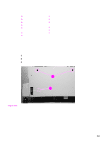
Registration assembly
1
Remove the right side cover. See page 152.
2
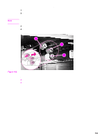
Remove four screws (callout 1).
CAUTION
Use care when following step 3. Three cables are connected to the registration assembly.
3
Gently lift the registration assembly off of tray 4, and unplug three connectors (callout 2) from the
rear of the registration assembly.
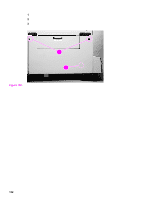
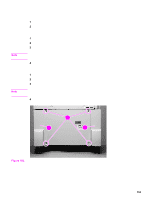
Note
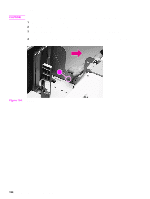
If you cannot reach the three cable connectors, remove the center back cover (page 153), remove the
right back cover (page 153), and unplug the connectors (figure 107, callout 3) from the back of tray 4.
Figure 106.
Registration assembly (1 of 2)
Figure 107.
Registration assembly (2 of 2)
2
2
2
1
2
3
2
3
2
3