HP LaserJet Pro 300 Service Manual
HP LaserJet Pro 300 Manual
 |
View all HP LaserJet Pro 300 manuals
Add to My Manuals
Save this manual to your list of manuals |
HP LaserJet Pro 300 manual content summary:
- HP LaserJet Pro 300 | Service Manual - Page 1
LASERJET PRO 300 COLOR LASERJET PRO 400 COLOR Service Manual M351 M451 - HP LaserJet Pro 300 | Service Manual - Page 2
- HP LaserJet Pro 300 | Service Manual - Page 3
HP LaserJet Pro 300 color M351 and HP LaserJet Pro 400 color M451 Printers Service Manual - HP LaserJet Pro 300 | Service Manual - Page 4
are set forth in the express warranty statements accompanying such products and services. Nothing herein should be construed as constituting an additional warranty. HP shall not be liable for technical or editorial errors or omissions contained herein. Part number: CE955-90964 Edition 1, 1/2012 - HP LaserJet Pro 300 | Service Manual - Page 5
Conventions used in this guide TIP: Tips provide helpful hints or shortcuts. NOTE: Notes provide important information to explain a concept or to complete a task. CAUTION: Cautions indicate procedures that you - HP LaserJet Pro 300 | Service Manual - Page 6
iv Conventions used in this guide ENWW - HP LaserJet Pro 300 | Service Manual - Page 7
screws ...5 Service approach ...6 Before performing service 6 After performing service 6 Post-service test ...6 and separation pad (Tray 1 15 Main assemblies ...18 Print-cartridge drawer 18 DIMM cover 20 Right cover 21 Reinstall the guide (simplex product 30 Remove the rear cover and feed - HP LaserJet Pro 300 | Service Manual - Page 8
duplex product 38 Remove the rear-door rib assembly (duplex product 38 Link guide 40 Upper-cover assembly 41 Reinstall the upper cover 43 Left cover 44 81 Color-misregistration sensor assembly PCA 84 Remove the color-misregistration sensor assembly PCA 84 Reinstall the color-misregistration - HP LaserJet Pro 300 | Service Manual - Page 9
assembly 98 2 Solve problems ...101 Solve problems checklist ...102 Menu map ...102 Troubleshooting process ...103 Pretroubleshooting Toner EMP diagram 118 Driver PCA diagram 119 Duplexer PCA diagram 120 FSR diagram 121 Internal print quality test pages 122 Print quality troubleshooting - HP LaserJet Pro 300 | Service Manual - Page 10
79 Service error Turn off then on 135 Black cartridge low 135 Black in wrong position 135 Black very low 135 Cleaning 136 Cyan cartridge low 136 Cyan in wrong position 136 Cyan very low 136 Device error Press [OK 137 Front door open 137 Genuine HP supply installed 137 Incompatible - HP LaserJet Pro 300 | Service Manual - Page 11
Manual feed Press [OK] for available media ....... 140 Memory is low Press [OK 140 Misprint Press [OK 141 Print failure, press OK. If error repeats, turn off then on 141 Rear door open 141 Remove shipping lock from cartridge problems 156 Print quality examples 156 Color - HP LaserJet Pro 300 | Service Manual - Page 12
be causing compatibility problems 168 The computer third-party firewall installed 170 The wireless Service mode functions ...173 Service menu ...173 Secondary service menu 174 Open the secondary service menu 174 Secondary service menu structure 174 Product resets ...175 Restore factory - HP LaserJet Pro 300 | Service Manual - Page 13
Service and support ...209 Hewlett-Packard limited warranty statement 210 HP's Premium Protection Warranty: LaserJet print cartridge limited warranty statement 212 Data stored on the print cartridge 213 End User production 225 Power consumption 225 Toner consumption 225 Paper use ...225 Plastics - HP LaserJet Pro 300 | Service Manual - Page 14
HP LaserJet print supplies 226 Return and recycling instructions 226 United States and Puerto Rico 226 Multiple returns (more than one cartridge 226 Single returns 226 Shipping 226 Non-U.S. returns 227 Paper ...227 Material restrictions 227 Disposal of waste equipment by users in private - HP LaserJet Pro 300 | Service Manual - Page 15
Vietnam Telecom wired/wireless marking for ICTQC Type approved products 240 Index ...241 ENWW xiii - HP LaserJet Pro 300 | Service Manual - Page 16
xiv ENWW - HP LaserJet Pro 300 | Service Manual - Page 17
Table 2-7 Event-log messages ...145 Table 2-8 2ndary Service menu ...174 Table 3-1 Order parts, accessories, and supplies 178 Table 3-2 Pro 300 Color M351a ...178 Table 3-3 Pro 400 Color MFP M451dn 178 Table 3-4 Pro 400 ColorMFP M451nw 178 Table 3-5 Pro 400 ColorMFP M451dw 178 Table 3-6 Related - HP LaserJet Pro 300 | Service Manual - Page 18
xvi ENWW - HP LaserJet Pro 300 | Service Manual - Page 19
of 3 17 Figure 1-14 Remove the Tray 1 separation pad 17 Figure 1-15 Remove the print-cartridge drawer (1 of 3 18 Figure 1-16 Remove the print-cartridge drawer (2 of 3 18 Figure 1-17 Remove the print-cartridge drawer (3 of 3 19 Figure 1-18 Remove the DIMM cover ...20 Figure 1-19 Remove the right - HP LaserJet Pro 300 | Service Manual - Page 20
(2 of 3 39 Figure 1-51 Remove the rear-door rib assembly (duplex product) (3 of 3 39 Figure 1-52 Replace the link guide (simplex products 40 Figure 1-53 Replace the link guide (duplex products 40 Figure 1-54 Remove the upper-cover assembly (1 of 4 41 Figure 1-55 Remove the upper-cover assembly - HP LaserJet Pro 300 | Service Manual - Page 21
Figure 1-76 Remove the right panel (5 of 8 54 Figure 1-77 Remove the right panel (6 of 8 55 Figure 1-78 Remove the right panel (7 of 8 55 Figure 1-79 Remove the right panel (8 of 8 56 Figure 1-80 Remove the front-door assembly (1 of 10 57 Figure 1-81 Remove the front-door assembly (2 of 10 - HP LaserJet Pro 300 | Service Manual - Page 22
high-voltage power-supply PCA (5 of 5 83 Figure 1-121 Remove the color-misregistration sensor assembly PCA (1 of 4 84 Figure 1-122 Remove the color-misregistration sensor assembly PCA (2 of 4 85 Figure 1-123 Remove the color-misregistration sensor assembly PCA (3 of 4 85 Figure 1-124 Remove the - HP LaserJet Pro 300 | Service Manual - Page 23
Figure 2-11 ASIC diagram ...117 Figure 2-12 HVT/Toner EMP diagram 118 Figure 2-13 Driver PCA diagram ...119 Figure 2-14 Duplexer PCA diagram ...120 Figure 2-15 FSR diagram ...121 Figure 3-1 Covers, panels, and doors 182 Figure 3-2 Internal assemblies (1 of 7 184 - HP LaserJet Pro 300 | Service Manual - Page 24
xxii ENWW - HP LaserJet Pro 300 | Service Manual - Page 25
1 Removal and replacement ● Removal and replacement strategy ● Service approach ● Removal and replacement procedures ENWW 1 - HP LaserJet Pro 300 | Service Manual - Page 26
HP does not support repairing individual subassemblies or troubleshooting to the component level. Note the length, diameter, color harness guides. troubleshooting. However, disconnect the power supply during parts removal. Never operate or service FFCs) during removal or installation. Also, do not - HP LaserJet Pro 300 | Service Manual - Page 27
. Electrostatic discharge CAUTION: Some parts are sensitive to electrostatic discharge (ESD). Look for the ESD reminder when removing product parts. Always perform service work at an ESD-protected workstation or mat, or use an ESD strap. If an ESD workstation, mat, or strap is not available - HP LaserJet Pro 300 | Service Manual - Page 28
be able to push the door pins out of the mounting holes. ● Small, slotted screwdriver ● Needle-nose pliers ● ESD mat (if one is available) ● Penlight (optional) CAUTION: Always use a Phillips screwdriver (callout 1). Do not use a pozidrive screwdriver (callout 2) or any motorized screwdriver. These - HP LaserJet Pro 300 | Service Manual - Page 29
for the correct shorter screw) can cause damage to the product or interfere with product operation. Do not intermix screws that are removed from one component with the screws that are removed from another component. NOTE: The screw illustrations in the following table are for reference only. Screws - HP LaserJet Pro 300 | Service Manual - Page 30
● Connect the interface cables, and then plug in the power cable. ● Reinstall the toner cartridges. ● Reinstall the Tray 2 cassette. Post-service test After service has been completed, perform the following test to verify that the repair or replacement was successful. Print-quality test 1. Verify - HP LaserJet Pro 300 | Service Manual - Page 31
Parts removal order Figure 1-2 Parts removal order (1 of 2) Figure 1-3 Parts removal order (2 of 2) ENWW Service approach 7 - HP LaserJet Pro 300 | Service Manual - Page 32
Removal and replacement procedures Tray 2 cassette Pull the tray straight out of the product to remove it. Figure 1-4 Remove the Tray 2 cassette 8 Chapter 1 Removal and replacement ENWW - HP LaserJet Pro 300 | Service Manual - Page 33
roller The transfer roller is a component of the paper-feed assembly and not available as an individual part. To remove and replace the transfer roller, install a replacement paper-feed assembly. See Paper-feed guide assembly on page 48. ENWW Removal and replacement procedures 9 - HP LaserJet Pro 300 | Service Manual - Page 34
Skin oils on the roller can cause paper-pickup problems. 1. Turn the product on, and wait for it to reach the Ready state. Perform the following steps to rotate the roller to the service position. NOTE: If you have removed Tray 2 to service the product, reinstall the tray before turning the product - HP LaserJet Pro 300 | Service Manual - Page 35
. WARNING! Do not place the product face-up resting on the rear cover and rear door. Excess toner might enter the laser/scanner assembly and contaminate the mirrors, causing print-quality problems. The laser/scanner is not a FRU. If the laser/scanner mirrors are contaminated, the entire product must - HP LaserJet Pro 300 | Service Manual - Page 36
1. Remove Tray 2 (if installed), and then carefully raise the front of the product. WARNING! Do not place the product face-up resting on the rear cover and rear door. Excess toner might enter the laser/scanner assembly and contaminate the mirrors, causing print-quality problems. The laser/scanner is - HP LaserJet Pro 300 | Service Manual - Page 37
2. Release the two roller-cover locking pins, and then remove the cover. Figure 1-8 Remove the separation roller (2 of 3) 3. Release the roller holder to release the roller-locking pins. Remove the separation roller. Figure 1-9 Remove the separation roller (3 of 3) ENWW Removal and replacement - HP LaserJet Pro 300 | Service Manual - Page 38
Reinstall the separation roller 1. Install the replacement separation roller. 2. Reinstall the separation roller cover on the locking pins, and then rotate it toward the roller until you hear it snap into place. Figure 1-10 Reinstall the separation roller 14 Chapter 1 Removal and replacement ENWW - HP LaserJet Pro 300 | Service Manual - Page 39
pad (Tray 1) The roller must be rotated into the service position to remove it. CAUTION: Avoid touching the spongy roller surface unless you are going to replace the roller. Skin oils on the roller can cause paper pickup problems. NOTE: Always replace the separation pad when replacing the paper - HP LaserJet Pro 300 | Service Manual - Page 40
. WARNING! Do not place the product face-up resting on the rear cover and rear door. Excess toner might enter the laser/scanner assembly and contaminate the mirrors, causing print-quality problems. The laser/scanner is not a FRU. If the laser/scanner mirrors are contaminated, the entire product must - HP LaserJet Pro 300 | Service Manual - Page 41
4. Release two tabs, and then rotate the roller away from the product to remove it. Figure 1-13 Remove the Tray 1 paper-pickup roller (3 of 3) 5. Release the retainer tabs, and then remove the separation pad from the base. CAUTION: The Tray 1 separation-pad spring is not captive. Do not lose the - HP LaserJet Pro 300 | Service Manual - Page 42
drawer, and then use a small, flat-blade screwdriver to release one tab (callout 1) on the left side of the product. Figure 1-15 Remove the print-cartridge drawer (1 of 3) 1 3. Carefully rotate the print-cartridge drawer toward the right side of the product to release it. Figure 1-16 Remove - HP LaserJet Pro 300 | Service Manual - Page 43
4. Pull the print-cartridge drawer out of the product to remove it. Figure 1-17 Remove the print-cartridge drawer (3 of 3) ENWW Removal and replacement procedures 19 - HP LaserJet Pro 300 | Service Manual - Page 44
DIMM cover 1. Open the DIMM cover. 2. Lift the cover up to release it, and then remove the cover. Figure 1-18 Remove the DIMM cover 20 Chapter 1 Removal and replacement ENWW - HP LaserJet Pro 300 | Service Manual - Page 45
Right cover 1. Remove the DIMM cover. See DIMM cover on page 20. 2. Open the rear cover, and then remove three screws (callout 1). Figure 1-19 Remove the right cover (1 of 5) 1 3. Before you proceed, take note of the mounting tab locations on the back of the cover. Figure 1-20 Remove the right cover - HP LaserJet Pro 300 | Service Manual - Page 46
4. Slide the right cover toward the back of the product. Figure 1-21 Remove the right cover (3 of 5) 5. Release one tab (callout 1). Figure 1-22 Remove the right cover (4 of 5) 1 22 Chapter 1 Removal and replacement ENWW - HP LaserJet Pro 300 | Service Manual - Page 47
cover NOTE: Do not reinstall the DIMM cover before reinstalling the right cover. The cover will interfere with the product chassis and prevent the correct installation of the right cover. ● Before you reinstall the right cover, take note of the mounting tab locations on the back of the cover. Figure - HP LaserJet Pro 300 | Service Manual - Page 48
Rear-upper cover (duplex product) 1. Open the rear cover. 2. Remove two screws (callout 1). Figure 1-25 Remove the rear-upper cover (1 of 2) 1 3. Slightly separate the cover from the product, and rotate the cover down and then away from the product to remove it. Figure 1-26 Remove the rear-upper - HP LaserJet Pro 300 | Service Manual - Page 49
, and then remove the link cap. TIP: It might be easier to remove the link caps if you remove the feed assembly. See Paper-feed guide assembly on page 48. Figure 1-27 Remove the rear-door stopper and link caps (simplex product) (1 of 2) 3. Use a small, flat-blade screwdriver to carefully remove - HP LaserJet Pro 300 | Service Manual - Page 50
, and then remove the link cap. TIP: It might be easier to remove the link cap if you remove the feed assembly. See Paper-feed guide assembly on page 48. Figure 1-29 Remove the rear door (simplex product) (1 of 4) 3. Remove four screws (callout 1). Figure 1-30 Remove the rear door (simplex product - HP LaserJet Pro 300 | Service Manual - Page 51
4. Before you remove the rear door, take note of the alignment pins on the door. Figure 1-31 Remove the rear door (simplex product) (3 of 4) 5. Remove the rear door. Figure 1-32 Remove the rear door (simplex product) (4 of 4) ENWW Removal and replacement procedures 27 - HP LaserJet Pro 300 | Service Manual - Page 52
Rear door (duplex product) 1. Open the rear door. 2. Use the green handle to close the duplex-feed assembly. Figure 1-33 Remove the rear door (duplex product) (1 of 4) 3. Remove two screws (callout 1). Figure 1-34 Remove the rear door (duplex product) (2 of 4) 1 28 Chapter 1 Removal and - HP LaserJet Pro 300 | Service Manual - Page 53
4. Before you remove the rear door, take note of the mounting tabs on the door. Figure 1-35 Remove the rear door (duplex product) (3 of 4) 5. Slide the door away from the product to release two tabs, and then remove the door. Figure 1-36 Remove the rear door (duplex product) (4 of 4) ENWW Removal - HP LaserJet Pro 300 | Service Manual - Page 54
page 26. ● Right cover. See Right cover on page 21. Remove the rear cover and feed guide (simplex product) 1. Carefully release the link guide from the pivot pin on the feed guide. Figure 1-37 Remove the rear cover and feed guide (simplex product) (1 of 6) 30 Chapter 1 Removal and replacement ENWW - HP LaserJet Pro 300 | Service Manual - Page 55
2. Remove three screws (callout 1). Figure 1-38 Remove the rear cover and feed guide (simplex product) (2 of 6) 1 3. Release two tabs (callout 1). Figure 1-39 Remove the rear cover and feed guide (simplex product) (3 of 6) 1 ENWW Removal and replacement procedures 31 - HP LaserJet Pro 300 | Service Manual - Page 56
4. Carefully lift the cover up, and then rotate it away from the product to remove it. Figure 1-40 Remove the rear cover and feed guide (simplex product) (4 of 6) 2 2 1 Reinstallation tip Make sure that the wire harnesses at the top of the chassis near the left-side cover are correctly retained - HP LaserJet Pro 300 | Service Manual - Page 57
5. Carefully release a feed-guide hinge pin from the rear cover to release the feed guide. Figure 1-41 Remove the rear cover and feed guide (simplex product) (5 of 6) 6. Remove the feed guide. Figure 1-42 Remove the rear cover and feed guide (simplex product) (6 of 6) ENWW Removal and replacement - HP LaserJet Pro 300 | Service Manual - Page 58
Rear-lower cover and rear-door links (duplex product) Before proceeding, remove the following components: ● Right cover. See Right cover on page 21. ● Rear-upper cover. See Rear-upper cover (duplex product) on page 24. ● Rear door. See Rear door (duplex product) on page 28. Remove the rear-lower - HP LaserJet Pro 300 | Service Manual - Page 59
and then slightly separate the cover from the product. Figure 1-44 Remove the rear-lower cover and rear-door links (duplex product) (2 of 6) 1 3. Release one tab (callout 1) and slightly separate the cover from the product. Figure 1-45 Remove the rear-lower cover and rear-door links (duplex product - HP LaserJet Pro 300 | Service Manual - Page 60
4. Close the duplex assembly, lift up on one side of the cover, and then lift up the other side of the cover to release it. Figure 1-46 Remove the rear-lower cover and link-guides (duplex product) (4 of 6) 5. Slightly lift up the rear-door rib assembly, and then carefully slide the cover away - HP LaserJet Pro 300 | Service Manual - Page 61
the rear-door link. Repeat this step for the remaining rear-door link. NOTE: If you are installing a replacement rear-lower cover, remove the rear-door links from the discarded cover, and then install them on the replacement cover. Figure 1-48 Remove the rear-lower cover and rear-door links (duplex - HP LaserJet Pro 300 | Service Manual - Page 62
page 34. Remove the rear-door rib assembly (duplex product) NOTE: The duplex fan (FM2) is a component of the rear-door rib assembly. 1. Disconnect one connector (callout 1). TIP: The PCA can be dislodged when disconnecting the connector. To secure the PCA, carefully push it towards the inside of the - HP LaserJet Pro 300 | Service Manual - Page 63
2. Slide the assembly toward the power cord side of the product to release the hinge pin. Figure 1-50 Remove the rear-door rib assembly (duplex product) (2 of 3) 3. Remove the assembly. Figure 1-51 Remove the rear-door rib assembly (duplex product) (3 of 3) ENWW Removal and replacement procedures - HP LaserJet Pro 300 | Service Manual - Page 64
assembly (duplex products; callout 3). If the link-guide attachment at the rear door or duplexing feed guide assembly fails, replace the appropriate component. The interior paper guide is not replaceable. If the link guide to paper guide attachment fails, you must replace the entire product. Figure - HP LaserJet Pro 300 | Service Manual - Page 65
1. Remove the Rear-upper cover. See Rear-upper cover (duplex product) on page 24. 2. Remove one screw (callout 1). Figure 1-54 Remove the upper-cover assembly (1 of 4) 1 3. Release one tab (callout 1). Figure 1-55 Remove the upper-cover assembly (2 of 4) 1 ENWW Removal and replacement procedures - HP LaserJet Pro 300 | Service Manual - Page 66
4. Before you proceed, take note of location of the top cover tabs. Figure 1-56 Remove the upper-cover assembly (3 of 4) 5. Carefully rotate the back side of the top cover up and off of the product to release the tabs, and then remove the cover. NOTE: When you reinstall the upper cover, ensure that - HP LaserJet Pro 300 | Service Manual - Page 67
Reinstall the upper cover ● When you reinstall the upper cover, ensure that the two tabs in the paper delivery area are fully seated into the chassis. Figure 1-58 Upper-cover tabs correctly seated Figure 1-59 Upper-cover tabs not correctly seated ENWW Removal and replacement procedures 43 - HP LaserJet Pro 300 | Service Manual - Page 68
cover on page 21. ● Rear cover (simplex products). See Rear cover and feed guide (simplex product) on page 30. ● Rear-lower cover (duplex products). See Rear on page 41. Remove the left cover 1. Remove one screw (callout 1). Figure 1-60 Remove the left cover (1 of 3) 1 44 Chapter - HP LaserJet Pro 300 | Service Manual - Page 69
2. Slightly lift up on the cover, and then rotate the top of the cover away from the product. Figure 1-61 Remove the left cover (2 of 3) 3. Remove the cover. Figure 1-62 Remove the left cover (3 of 3) ENWW Removal and replacement procedures 45 - HP LaserJet Pro 300 | Service Manual - Page 70
Reinstall the left cover 1. When you reinstall the left cover, ensure that the slot in the cover (callout 1) aligns with the tab (callout 2) on the product. Figure 1-63 Reinstall the left cover (1 of 2) 2 1 2. When you reinstall the left cover, ensure that the pin on the cover (callout 1) aligns - HP LaserJet Pro 300 | Service Manual - Page 71
Control-panel assembly on page 50. ● Right panel. See Right panel on page 52. Remove the right-front cover and power button 1. Lift up on one tab (callout 1) and then slide the right-front cover toward the top edge of the right panel to separate the cover from the panel. Figure - HP LaserJet Pro 300 | Service Manual - Page 72
assembly NOTE: A simplex model is shown below. Duplex and simplex models use the same paper-feed guide assembly, and the removal and replacement processes are identical. 1. Remove one screw (callout 1). CAUTION: The bushing on this screw is not captive. Do not lose the bushing when the screw is - HP LaserJet Pro 300 | Service Manual - Page 73
2. Remove the feed assembly. CAUTION: Do not touch the black sponge portion of the roller. Skin oils on the roller can cause print-quality problems. Reinstallation tip When the feed assembly is correctly reinstalled, the assembly can move in relation to the door. It should not be secured firmly to - HP LaserJet Pro 300 | Service Manual - Page 74
not bend or fold the flat flexible cables (FFCs) during removal or installation. Also, do not straighten prefolds in the FFCs. You must ensure that can cause a short circuit in a PCA. 1. Disconnect one FFC (callout 1), and then remove one screw (callout 2). Figure 1-69 Remove the control-panel - HP LaserJet Pro 300 | Service Manual - Page 75
2. Open the front door, and then remove two screws (callout 1). Figure 1-70 Remove the control-panel assembly (2 of 3) 1 3. Remove the control-panel assembly. Figure 1-71 Remove the control-panel assembly (3 of 3) ENWW Removal and replacement procedures 51 - HP LaserJet Pro 300 | Service Manual - Page 76
-cover assembly. See Upper-cover assembly on page 41. ● Control-panel assembly. See Control-panel assembly on page 50. Remove the right panel 1. Disconnect one connector (callout 1; J206) on the DC controller. Figure 1-72 Remove the right panel (1 of 8) 1 52 Chapter 1 Removal and replacement ENWW - HP LaserJet Pro 300 | Service Manual - Page 77
2. Remove three screws (callout 1). Figure 1-73 Remove the right panel (2 of 8) 1 3. Remove three screws (callout 1). Figure 1-74 Remove the right panel (3 of 8) 3 ENWW Removal and replacement procedures 53 - HP LaserJet Pro 300 | Service Manual - Page 78
4. Disconnect two connectors (callout 1), release the fan wire harness from the guide (callout 2), and then remove three screws (callout 3). Figure 1-75 Remove the right panel (4 of 8) 1 3 2 5. Place the power button in the on position (callout 1). TIP: When - HP LaserJet Pro 300 | Service Manual - Page 79
6. Carefully rotate the back edge of the panel away from the product. Figure 1-77 Remove the right panel (6 of 8) 7. Carefully push the panel slightly toward the front of the product to release it. Figure 1-78 Remove the right panel (7 of 8) ENWW Removal and replacement procedures 55 - HP LaserJet Pro 300 | Service Manual - Page 80
cover includes the power button) from the right panel. See Fan on page 88 and Right-front cover and power button on page 47. Figure 1-79 Remove the right panel (8 of 8) 56 Chapter 1 Removal and replacement ENWW - HP LaserJet Pro 300 | Service Manual - Page 81
proceeding, remove the following components: ● Print-cartridge drawer. See Print-cartridge drawer on page 18 ● Right cover. simplex product) on page 26. ● Rear cover (simplex products). See Rear cover and feed guide (simplex product) on page 30. ● Rear-upper cover (duplex products). See Rear-upper - HP LaserJet Pro 300 | Service Manual - Page 82
2. Use a precision point screwdriver to push the left-side door pin out of the link. NOTE: A precision-point screwdriver is required to release the front door pins. The width of the blade must be 2 mm (0.08 in) or less to be able to push the door pins out of the mounting holes. Figure 1-81 Remove - HP LaserJet Pro 300 | Service Manual - Page 83
4. Remove two screws (callout 1) and separate the door bushing (callout 2) from the chassis. Figure 1-83 Remove the front-door assembly (4 of 10) 2 1 5. Release the bushing from the door-retainer link (callout 1). Figure 1-84 Remove the front-door assembly (5 of 10) 1 ENWW Removal and replacement - HP LaserJet Pro 300 | Service Manual - Page 84
the door assembly, and carefully release the pin on the right-side link. Figure 1-85 Remove the front-door assembly (6 of 10) 7. Support the door assembly, and carefully release the upper pin on the left-side link. Figure 1-86 Remove the front-door assembly (7 of 10) 60 Chapter 1 - HP LaserJet Pro 300 | Service Manual - Page 85
8. Push the black-plastic arm into the product. Figure 1-87 Remove the front-door assembly (8 of 10) 9. Support the door assembly, and carefully release the lower pin on the left-side link. Figure 1-88 Remove the front-door assembly (9 of 10) ENWW Removal and replacement procedures 61 - HP LaserJet Pro 300 | Service Manual - Page 86
the front-door assembly. Figure 1-89 Remove the front-door assembly (10 of 10) Reinstall the front-door assembly Use this procedure if you are installing a replacement front-door assembly. 1. Open Tray 1, and then rotate the retainer arm until the tabs on the arm-hinge pin align with the slots in - HP LaserJet Pro 300 | Service Manual - Page 87
2. Remove the retainer arm from the door assembly, and then install it on the replacement-door assembly. Figure 1-91 Reinstall the front-door assembly (2 of 2) ENWW Removal and replacement procedures 63 - HP LaserJet Pro 300 | Service Manual - Page 88
Intermediate transfer belt (ITB) 1. Remove the print-cartridge drawer. See Print-cartridge drawer on page 18. 2. Open the front door, and then remove two screws (callout 1). Figure 1-92 Remove the ITB (1 of 6) 1 3. Carefully rotate the color misregistration sensor away from the ITB. CAUTION: The - HP LaserJet Pro 300 | Service Manual - Page 89
4. Disconnect one connector (callout 1). Figure 1-94 Remove the ITB (3 of 6) 2 5. Carefully lift up on the front of the ITB to release it. CAUTION: Avoid touching the black plastic transfer belt. Skin oils on the belt might cause printquality problems. Lift the ITB as shown below by using the hard- - HP LaserJet Pro 300 | Service Manual - Page 90
portion (callout 1). CAUTION: Avoid touching the black plastic transfer belt. Skin oils on the belt might cause printquality problems. NOTE: You might need to reach in through the front door and support the front portion of the ITB to keep it from falling back into place as you perform this step - HP LaserJet Pro 300 | Service Manual - Page 91
page. See the complete version of the English service manual. 2. Verify that rows one through four, columns A through I (callout 1) installed. See Figure 1-93 Remove the ITB (2 of 6) on page 64 and Figure 1-92 Remove the ITB (1 of 6) on page 64. Figure 1-98 Reinstall the ITB HP Color LaserJet PRO - HP LaserJet Pro 300 | Service Manual - Page 92
procedure can be used to remove motor M1 or motor M2 separately. CAUTION: HP does not recommend that you remove or replace both motors at the same time. 1. Remove the right cover. See Right cover on page 21. 2. Disconnect one connector (callout 1) for motor M1 or motor M2. NOTE: The drum motor - HP LaserJet Pro 300 | Service Manual - Page 93
: Additional connectors might need to be disconnected to release the wire harnesses from the retainer. Figure 1-100 Remove motor M1 and motor M2 (2 of 5) 1 4. Release one tab (callout 1). Figure 1-101 Remove motor M1 and motor M2 (3 of 5) 1 ENWW Removal and replacement procedures 69 - HP LaserJet Pro 300 | Service Manual - Page 94
5. Rotate the top of the retainer away from the chassis, and then lift it up to remove it. Figure 1-102 Remove motor M1 and motor M2 (4 of 5) 6. Remove three screws (callout 1) to remove motor M1, or remove three screws (callout 2) to remove motor M2. Figure 1-103 Remove motor M1 and motor M2 (5 of - HP LaserJet Pro 300 | Service Manual - Page 95
Reinstall the drum motor (M1) and developer motor (M2) When the motor wire harness retainer is reinstalled, the two tabs at the bottom of the retainer must be positioned behind the retainer on the low-voltage power supply. The tab at the side of motor wire harness retainer must be positioned behind - HP LaserJet Pro 300 | Service Manual - Page 96
assembly on page 41. ● Right panel. See Right panel on page 52. Remove the intermediate PCA 1. Disconnect all the connectors (callout 1) on the PCA and one FFC (callout 2). Figure 1-105 Remove the Intermediate PCA (1 of 2) 1 2 72 Chapter 1 Removal and replacement ENWW - HP LaserJet Pro 300 | Service Manual - Page 97
2. Remove three screws (callout 1), and then remove the intermediate PCA. Figure 1-106 Remove the Intermediate PCA (2 of 2) 1 ENWW Removal and replacement procedures 73 - HP LaserJet Pro 300 | Service Manual - Page 98
print-quality problems. NOTE: The base model does not have a fax card installed. Replacing Install a replacement formatter PCA. 2. Turn the product on, and wait for the print-cartridge sensitive to electrostatic discharge (ESD). Always perform service work at an ESDprotected workstation or mat. If - HP LaserJet Pro 300 | Service Manual - Page 99
2. Disconnect all the connectors. Figure 1-107 Remove the formatter PCA (1 of 2) 3. Remove four screws (callout 1), and then remove the formatter PCA. Figure 1-108 Remove the formatter PCA (2 of 2) 1 ENWW Removal and replacement procedures 75 - HP LaserJet Pro 300 | Service Manual - Page 100
severe print-quality problems. Replacing the DC controller PCA before the formatter PCA Use the following procedure if you need to install a replacement DC on page 76. 1. Install a replacement DC controller PCA. 2. Turn the product on, and wait for the print-cartridge volume indicators to appear on - HP LaserJet Pro 300 | Service Manual - Page 101
fold the flat flexible cables (FFCs) during removal or installation. Also, do not straighten prefolds in the FFCs. You circuit in a PCA. Some parts are sensitive to electrostatic discharge (ESD). Always perform service work at an ESDprotected workstation or mat. If an ESD workstation or mat is not - HP LaserJet Pro 300 | Service Manual - Page 102
product) on page 26. ● Rear cover (simplex products). See Rear cover and feed guide (simplex product) on page 30. ● Upper-cover assembly. See Upper-cover assembly on plate. CAUTION: The four flat-head screws must be installed in the correct position to avoid damage to the formatter. Standard screws can - HP LaserJet Pro 300 | Service Manual - Page 103
2. Disconnect one connector (callout 1) and remove the wire from the retainer (callout 2). Figure 1-112 Remove the fuser motor assembly (2 of 4) 1 2 1), and then remove the fuser motor assembly. Figure 1-113 Remove the fuser motor assembly (3 of 4) 1 ENWW Removal and replacement procedures 79 - HP LaserJet Pro 300 | Service Manual - Page 104
and slot provided in the assembly mounting bracket. The assembly mounting bracket fits flat against the product chassis when the fuser motor assembly is correctly installed. Figure 1-115 Reinstall the fuser motor assembly 1 2 80 Chapter 1 Removal and replacement ENWW - HP LaserJet Pro 300 | Service Manual - Page 105
page 24. ● Rear door (simplex products). See Rear door (simplex product) on page 26. ● Rear cover (simplex products). See Rear cover and feed guide (simplex product) on page 30. Remove the high-voltage power-supply PCA 1. Remove two screws (callout 1), and then remove the sheet-metal plate (callout - HP LaserJet Pro 300 | Service Manual - Page 106
Release six tabs (callout 1), and then remove the black-plastic cover. Figure 1-117 Remove the high-voltage power-supply PCA (2 of 5) 1 3. Disconnect one FFC (callout 1) on the DC controller. Figure 1-118 Remove the high-voltage power-supply PCA (3 of 5) 1 82 Chapter 1 Removal and replacement ENWW - HP LaserJet Pro 300 | Service Manual - Page 107
4. Disconnect one connector (callout 1), and then remove six screws (callout 2). Figure 1-119 Remove the high-voltage power-supply PCA (4 of 5) 1 2 5. Release ten tabs (callout 1), and then remove - HP LaserJet Pro 300 | Service Manual - Page 108
Color-misregistration sensor assembly PCA Before proceeding, remove the following components: ● Print-cartridge drawer. See Print-cartridge drawer on page 18. one connector (callout 1), and then release the wire harness from the guide (callout 2). Figure 1-121 Remove the color-misregistration - HP LaserJet Pro 300 | Service Manual - Page 109
3. Release the wire harness from the guide (callout 1). NOTE: When you remove the sensor assembly later in this procedure, pass the connector and wire harness through the hole in the chassis (callout 2). Figure 1-122 Remove the color-misregistration sensor assembly PCA (2 of 4) 1 2 4. Remove two - HP LaserJet Pro 300 | Service Manual - Page 110
the assembly. NOTE: See callout 1 in Figure 1-122 Remove the color-misregistration sensor assembly PCA (2 of 4) on page 85. Figure 1-124 Remove the color-misregistration sensor assembly PCA (4 of 4) Reinstall the color-misregistration sensor assembly TIP: You might have to attempt this reinstall - HP LaserJet Pro 300 | Service Manual - Page 111
2. Use a small flat blade screwdriver to guide the connector through the hole. Figure 1-126 Reinstall the color-misregistration sensor assembly PCA (2 of 2) ENWW Removal and replacement procedures 87 - HP LaserJet Pro 300 | Service Manual - Page 112
(callout 1) and then release the wire harness from the retainer (callout 2). Figure 1-127 Remove the fan (1 of 2) 1 2 3. Release one tab (callout 1), push down on the fan to release it from the mounting points (callout 2), and then remove the fan. Figure 1-128 Remove the fan (2 - HP LaserJet Pro 300 | Service Manual - Page 113
) on page 26. ● Rear door (duplex products). See Rear door (duplex product) on page 28. ● Rear cover (simplex products). See Rear cover and feed guide (simplex product) on page 30. ● Rear-lower cover (duplex products). See Rear-lower cover and rear-door links (duplex product) on page 34. ● Upper - HP LaserJet Pro 300 | Service Manual - Page 114
2. Release the wire harnesses from the retainer (callout 1). Figure 1-130 Remove the duplex reverse-drive assembly (2 of 4) 1 3. Remove three screws (callout 1). Figure 1-131 Remove the duplex reverse-drive assembly (3 of 4) 1 90 Chapter 1 Removal and replacement ENWW - HP LaserJet Pro 300 | Service Manual - Page 115
4. Remove the duplex reverse-drive assembly. Figure 1-132 Remove the duplex reverse-drive assembly (4 of 4) ENWW Removal and replacement procedures 91 - HP LaserJet Pro 300 | Service Manual - Page 116
assembly. See Upper-cover assembly on page 41. ● Left cover. See Left cover on page 44. ● Rear cover (simplex products). See Rear cover and feed guide (simplex product) on page 30. ● Rear-lower cover (duplex products). See Rear-lower cover and rear-door links (duplex product) on page 34. Remove the - HP LaserJet Pro 300 | Service Manual - Page 117
the wire harnesses from the guide (callout 2). Reinstallation tip When the upper cover is reinstalled, make sure that these wire harnesses (near the connectors) are correctly routed under the cover. Figure 1-134 Remove the fuser (2 of 8) 1 2 3. Disconnect one connector (callout 1). Figure 1-135 - HP LaserJet Pro 300 | Service Manual - Page 118
much force and damage the lower portion of the guide. If the guide is damaged, the fuser must be replaced. Figure 1-136 Remove the fuser (4 of 8) 5. Carefully disconnect one connector and rotate the connector and the top portion of the guide away from the fuser (callout 1). WARNING! Do not separate - HP LaserJet Pro 300 | Service Manual - Page 119
6. Remove two screws (callout 6). Figure 1-138 Remove the fuser (6 of 8) 6 7. Remove the fuser. Figure 1-139 Remove the fuser (7 of 8) ENWW Removal and replacement procedures 95 - HP LaserJet Pro 300 | Service Manual - Page 120
8. Duplex models only: Remove two screws (callout 1) and remove the duplex-gear assembly (callout 2). Install the assembly on the replacement fuser. Figure 1-140 Remove the fuser (8 of 8) 2 1 96 Chapter 1 Removal and replacement ENWW - HP LaserJet Pro 300 | Service Manual - Page 121
1) on the fuser frame into the slots on the product chassis (callout 2). WARNING! The fuser frame must be flush against the product chassis before you install the two fuser mounting screws. Do not use the screws to pull the fuser frame against the chassis. Figure 1-141 Reinstall the fuser 2 1 ENWW - HP LaserJet Pro 300 | Service Manual - Page 122
product) on page 26. ● Rear door (duplex products). See Rear door (duplex product) on page 28. ● Rear cover (simplex products). See Rear cover and feed guide (simplex product) on page 30. ● Upper-cover assembly. See Upper-cover assembly on page 41. ● Left cover. See Left cover on page 44. ● Rear - HP LaserJet Pro 300 | Service Manual - Page 123
2. Disconnect two connectors (callout 1), and then release the wire harnesses from the wire clip (callout 2). Figure 1-143 Remove the paper-delivery assembly (2 of 4) 2 1 3. Remove three screws (callout 1). Figure 1-144 Remove the paper-delivery assembly (3 of 4) 1 ENWW Removal and replacement - HP LaserJet Pro 300 | Service Manual - Page 124
4. Remove the paper-delivery assembly. Figure 1-145 Remove the paper-delivery assembly (4 of 4) 100 Chapter 1 Removal and replacement ENWW - HP LaserJet Pro 300 | Service Manual - Page 125
the printer systems, and the basic theory of operation are contained in LASERJET PRO 300/400 COLOR Theory of Operation. Do not perform any of these troubleshooting processes unless you understand the function of each product component. ● Solve problems checklist ● Menu map ● Troubleshooting process - HP LaserJet Pro 300 | Service Manual - Page 126
toner cartridge installed correctly, and was the pull tab on the cartridge removed? For additional information about installation and setup, see the product getting started guide. If you cannot find solutions to problems in this guide, go to www.hp.com/support/LJColorM351 or www.hp.com/support - HP LaserJet Pro 300 | Service Manual - Page 127
problem and to reduce the number of steps that are required to fix the problem. ● Use the troubleshooting flowchart to pinpoint the root cause of hardware malfunctions. The flowchart guides problem. General topic Environment Media Input trays Questions ● Is the product installed only supported media - HP LaserJet Pro 300 | Service Manual - Page 128
temperature for 1 to 2 hours. ● Check for and remove any non-HP components (for example, toner cartridges or memory modules) from the product. ● Check to see whether the hardware or software configuration has changed or the problem is not associated with any specific software. ● Remove the product - HP LaserJet Pro 300 | Service Manual - Page 129
a surge protector or power strip. ● Verify that the power button is in the on position. ● Verify that the formatter is seated correctly. ● Remove any HP Jetdirect or other devices, and then try to turn the product on again. ● Ensure that the control-panel display is connected. ● Check the two fuses - HP LaserJet Pro 300 | Service Manual - Page 130
the toner cartridge colors) prints. Figure 2-1 Engine test button location Diagrams Plug/jack locations 1 Network port (HP LaserJet Pro 300 color M351a, HP LaserJet Pro 300 color M351dw, and HP LaserJet Pro 300 color M351dn models only) 2 Hi-Speed USB 2.0 port 106 Chapter 2 Solve problems ENWW - HP LaserJet Pro 300 | Service Manual - Page 131
controller connectors Item Description J130 Formatter J131 Laser-driver PCA J132 Scanner motor (M7) J133 High-voltage power supply J140 Motor-driver PCA J141 Relay PCA J150 Fuser J151 Low-voltage and fuser power supply J152 Duplex driver PCA (duplex models only) ENWW Tools for troubleshooting 107 - HP LaserJet Pro 300 | Service Manual - Page 132
Description 1 Dulpex feed assembly (duplex models only) 2 Rear-door rib assembly (duplex models only) 3 Power supply (low-voltage and fuser) Item Description 8 Fuser 9 Paper-feed guide assembly (includes the transfer roller) 10 Cassette pickup assembly 108 Chapter 2 Solve - HP LaserJet Pro 300 | Service Manual - Page 133
14 Description Duplex repick assembly (duplex models only) MP tray pickup assembly Drive assembly Color misregistration sensor Solenoids, clutches, and sensors Figure 2-4 Solenoid, clutches, and sensors SR15 solenoid (in the optional paper feeder; not shown) ENWW Tools for troubleshooting 109 - HP LaserJet Pro 300 | Service Manual - Page 134
Table 2-3 Solenoid, clutches, and sensors (continued) Item Description SR12 Pre-registration sensor SR13 Cassette media presence sensor Item Description CL1 MP tray feed clutch CL2 Duplex feed clutch (duplex models only) 110 Chapter 2 Solve problems ENWW - HP LaserJet Pro 300 | Service Manual - Page 135
Rollers Figure 2-5 Rollers 3 4 Table 2-4 Rollers Item Description 1 Cassette pickup roller 2 MP tray pickup roller 1 2 Item Description 3 MP tray separation pad 4 Cassette separation roller ENWW Tools for troubleshooting 111 - HP LaserJet Pro 300 | Service Manual - Page 136
illustration. Item Description 1 Fuser motor (M4) 2 Drum motor (M1) 3 Developing motor (M2) Item Description 4 Fan 1 5 Fan 2 (duplex models only) 6 Pickup motor (M5) 112 Chapter 2 Solve problems ENWW - HP LaserJet Pro 300 | Service Manual - Page 137
PCAs Figure 2-7 PCAs 6 1 5 2 3 4 Table 2-5 PCAs Item Description 1 DC controller PCA 2 Connector PCA (relay PCA) 3 Driver PCA Item Description 4 High-voltage power supply PCA 5 Formatter 6 Sub-power PCA ENWW Tools for troubleshooting 113 - HP LaserJet Pro 300 | Service Manual - Page 138
General timing charts Approximate timing in seconds. Figure 2-8 Timing diagram Fuser Fuser Fuser 114 Chapter 2 Solve problems ENWW - HP LaserJet Pro 300 | Service Manual - Page 139
General circuit diagram Figure 2-9 Circuit diagram PCA PCA Fuser PCA Fuser Fuser PCA PCA Fuser PCA PCA PCA PCA PCA PCA Fuser PCA PCA Fuser ENWW Tools for troubleshooting 115 - HP LaserJet Pro 300 | Service Manual - Page 140
85 84 83 82 81 3 2 1 (A503) 80 79 12 C11 0.1U,25V 78 77 N.C. 76 1 check VOUT 4 C9 0.1U,25V 12 RESET IC NJU7704F29A-@-#ZZZB C10 12 0.1U,25V/NOTMNT 75 RESET 74 WAKEENG (A503) 73 CCRT CPU 2: ASIC 3: VIF, LSR, SCN, HVT,TG 4: DRIVER PCA, SENSOR MODE0 MODE2 5: FSR, LVT, DUP , OPT - HP LaserJet Pro 300 | Service Manual - Page 141
0.1U,25V 96 95 94 93 92 91 90 89 88 87 86 85 84 83 82 81 80 79 78 77 76 75 74 73 72 71 70 69 68 67 66 65 12 12 IC2 C101 0.1U ) (A503) (A503) (A503) (A505) (A503) (A503) (A503) (A503) (A503) (A505) (A505) (A505) (A505) 2: ASIC A CD1-4 F E D C B ENWW Tools for troubleshooting 117 - HP LaserJet Pro 300 | Service Manual - Page 142
EMP diagram Figure 2-12 HVT/Toner EMP diagram 7 6 +3.3VB J130 1 J23P J130 2 J23P J130 3 J23P VDOEN Q7 3 2 1 R241 330,0.063W D1 2 1 RT1N436M-@111 CCRT (CPU 9615S-29A-PP-A C115 0.01U,50V 3: VIF, LSR, SCN, HVT,TG VDO4 A +3.3VB > CD1-5 118 Chapter 2 Solve problems ENWW - HP LaserJet Pro 300 | Service Manual - Page 143
DEVMDEC (ASIC-54p) J140 1 J29P DEVMACC (ASIC-55p) VS1-6849029 9615S-29A-PP-A 6 5 4 3 2 1 +3.3VB 4.7K,0.063W 2 R181 +3.3VB +3.3VB 50V/NOTMNT VS1-7145007 2-292207-7 4: DRIVER PCA, SENSOR A VS1-7327017 55447-1770 CD1-6 ENWW Tools for troubleshooting 119 - HP LaserJet Pro 300 | Service Manual - Page 144
-8 CP900 1 check Zebra pattern JNT4 1J 2 R903 0,1AW/NOTMNT 2 1 5: FSR, LVT, DUP , OPT, ENV, DEVSL A > for HVT VS1-7145010 3-292207-0 > 120 Chapter 2 Solve problems Duplexer PCA diagram Figure 2-14 Duplexer PCA diagram CD1-7 - HP LaserJet Pro 300 | Service Manual - Page 145
2 JNT5 1 2J 3 FSRRLD2 (A505) R863 1 2 3.3K,0.1W 3 R861 1 2 4.7K,0.1W 1 2 Q863 2SC3624-@-A 2 2 JP6 RK73Z1JT/NOTMNT 1 JP7 1 RK73Z1JT +3.3VD CP100 1 check 1 F E D C B 6: FSR A CD1-8 ENWW Tools for troubleshooting 121 - HP LaserJet Pro 300 | Service Manual - Page 146
print quality test pages Print quality troubleshooting page The print quality page helps solve problems with print quality. Print a this page to check for color-plane registration and cartridge half tones. Print a configuration page from the product or from one of the Toolbox software programs. - HP LaserJet Pro 300 | Service Manual - Page 147
roller (one rotation) HP ToolboxFX. This is now called "HP Device Toolbox?" 2. Click the System tab, and then click the Print Quality link. 3. In the area for Color Calibration, select the Calibrate Now check box. 4. Click Apply to calibrate the product immediately. ENWW Tools for troubleshooting - HP LaserJet Pro 300 | Service Manual - Page 148
all the PCL6 fonts that are installed Prints a report that shows the user name, application name, and color usage information on a job-by-job basis Prints the service report Prints the calibration and color diagnostics pages Prints a page that helps solve problems with print quality Sub-menu item - HP LaserJet Pro 300 | Service Manual - Page 149
for writing music System Setup menu In the following table, items that have asterisks (*) indicate the factory default setting. Menu item Language Paper Setup Sub-menu item Sub-menu item Sub-menu item Def. arrow buttons to increase or decrease the time. ENWW Tools for troubleshooting 125 - HP LaserJet Pro 300 | Service Manual - Page 150
Quality Sub-menu item Calibrate Color Sub-menu item After Power error first. Use this menu to shift the margin alignment to center the image on the page from top to bottom and from left to right. Before adjusting these values, print a test page. It provides alignment guides 2 Solve problems ENWW - HP LaserJet Pro 300 | Service Manual - Page 151
standard replacement black print cartridge, the default is 13%. For the high-capacity replacement black print cartridge, the default is 7%. The default values are intended to provide approximately two weeks of use before the cartridge reaches the very low state. ENWW Tools for troubleshooting 127 - HP LaserJet Pro 300 | Service Manual - Page 152
item Very Low Setting Sub-menu item Stop Prompt* Continue Print Black Low Threshold Cyan Magenta Yellow Description Set how the product behaves when the one of the color print cartridges reaches the very low threshold. ● Prompt: The product stops printing and prompts you to replace the print - HP LaserJet Pro 300 | Service Manual - Page 153
studied in order to improve future HP products. The data collected from the print cartridge memory chip does not contain information that can be used to identify a customer or user of the print cartridge or their product. Select a version of the Courier font. Service menu Use this menu to restore - HP LaserJet Pro 300 | Service Manual - Page 154
toner smearing and dusting. Displays the current firmware datecode. Sets all customized menu settings to the factory default values. Enable or disable the HP Smart Install IP Config Network Test Wireless Off/On Automatic* Manual Auto Crossover Network Services Show IP Address On* Off IPv4 IPv6 No - HP LaserJet Pro 300 | Service Manual - Page 155
Link Speed HTTPS Enforced Restore Defaults Sub-menu item Automatic* 10T Full 10T Half 100TX Full 100TX Half No* Yes Description Sets the link speed manually if needed. After setting the link speed, the product automatically restarts. Sets the product so it communicates only with Web sites that use - HP LaserJet Pro 300 | Service Manual - Page 156
. Turning off and then turning on the power might fix the problem. If a critical error persists, the product might require service. Control panel messages 10.XXXX Supply error Description The memory chip for one of the print cartridges cannot be read or is missing. ◦ 10.0000 = black memory chip - HP LaserJet Pro 300 | Service Manual - Page 157
Turn the product on. If the message persists, contact HP support. 54.XX Error Turn off then on Description The product has experienced an error with one of the internal sensors. Recommended action Turn the product power the wall socket. Turn the product power on. ENWW Tools for troubleshooting 133 - HP LaserJet Pro 300 | Service Manual - Page 158
the message persists, contact HP support. 59.X Error Turn off then on Description The product has experienced a problem with one of the motors. Recommended HP support. 79 Error Turn off then on Description The product has experienced an internal firmware error. 134 Chapter 2 Solve problems ENWW - HP LaserJet Pro 300 | Service Manual - Page 159
, contact HP support. 79 Service error Turn off then on Description An incompatible DIMM is installed. Recommended action 1. Turn the product power off. 2. Install a DIMM that the product supports. 3. Turn the product on. If the message persists, contact HP support. Black cartridge low Description - HP LaserJet Pro 300 | Service Manual - Page 160
to back, the print cartridges are installed in this order: black, cyan, magenta, and yellow. Cyan very low Description The print cartridge is at the end of its useful life. A customer configurable option on this product is "Prompt to Remind Me in 100 pages, 200 pages, 300 pages, or never." This - HP LaserJet Pro 300 | Service Manual - Page 161
supplies Description More than one print cartridge is installed in the incorrect slot. Recommended action Be sure that each print cartridge is in the correct slot. From front to back, the print cartridges are installed in this order: black, cyan, magenta, yellow. ENWW Tools for troubleshooting 137 - HP LaserJet Pro 300 | Service Manual - Page 162
Install cartridge Description The print cartridge is either not installed or not correctly installed in the product. Recommended action Install the print cartridge. Invalid driver Press [OK] Description You are using an incorrect printer driver. Recommended action Select the correct printer - HP LaserJet Pro 300 | Service Manual - Page 163
Description The print cartridge is installed in the incorrect slot. Recommended action Make sure that each print cartridge is installed in the correct slot. From front to back, the print cartridges are installed in this order: black, cyan, magenta, and yellow. ENWW Tools for troubleshooting 139 - HP LaserJet Pro 300 | Service Manual - Page 164
low mode will not be considered to be defects in materials or workmanship in the supply under the HP Print Cartridge Warranty Statement. Manual duplex Load tray Press [OK] Description The first side of a manual duplex job has printed, and the page needs to be loaded to process the second side - HP LaserJet Pro 300 | Service Manual - Page 165
A print cartridge shipping lock is installed. Recommended action Pull the orange tab to remove the shipping lock from the cartridge. Remove shipping locks from cartridges Description A print cartridge shipping lock is installed on one or more print cartridges. ENWW Tools for troubleshooting 141 - HP LaserJet Pro 300 | Service Manual - Page 166
have loaded. Unsupported Press [OK] to continue Description The product has detected a print cartridge that was not made by HP. Recommended action Press the OK button to continue printing. If you believe you purchased an HP supply, go to www.hp.com/go/anticounterfeit. Service or repairs that - HP LaserJet Pro 300 | Service Manual - Page 167
installed Press [OK] to continue Description You have installed a print cartridge that reached the default low threshold while it was installed in another product. Recommended action Press the OK button to continue. Used supplies in use Description You are using more than one print cartridge - HP LaserJet Pro 300 | Service Manual - Page 168
on that supply has ended. All print defects or cartridge failures incurred when an HP supply is used in continue at very low mode will not be considered to be defects in materials or workmanship in the supply under the HP Print Cartridge Warranty Statement. 144 Chapter 2 Solve problems ENWW - HP LaserJet Pro 300 | Service Manual - Page 169
Error log code error Fuser heater wire failure Fuser low temperature subtherm failure Fuser high temperature subtherm failure Scanner error, black laser failure Scanner error, cyan laser failure Scanner error, magenta laser failure Scanner error, yellow laser failure ENWW Tools for troubleshooting - HP LaserJet Pro 300 | Service Manual - Page 170
density contaminated Sensor color plane registration contaminated Engine comm fatal error Engine comm critical error DC controller memory error ITB rotation failure ITB ramp up failure Color-plane registration error DMAX calibration error DHALF calibration error 146 Chapter 2 Solve problems ENWW - HP LaserJet Pro 300 | Service Manual - Page 171
Use only paper that meets HP specifications for this product. guides so they are touching the paper stack without bending it. 6. Make sure that the tray is fully inserted in the product. 7. If you are printing on heavy, embossed, or perforated paper, use the manual feed feature and feed sheets one - HP LaserJet Pro 300 | Service Manual - Page 172
Clear jams in Tray 1 1. Pull the jammed sheet from Tray 1. NOTE: If the sheet tears, make sure that all of the fragments are removed before you resume printing. 2. Pull out Tray 2 and place it on a flat surface. 3. Lower the jam-access tray. 148 Chapter 2 Solve problems ENWW - HP LaserJet Pro 300 | Service Manual - Page 173
4. Remove the jammed sheet by pulling it straight out. 5. Push the jam-access tray up to close it, and then replace Tray 2. NOTE: To close the tray, push in the middle or with even pressure on both sides. Avoid pushing on one side only. Clear jams in Tray 2 1. Open Tray 2. ENWW Clear jams 149 - HP LaserJet Pro 300 | Service Manual - Page 174
pulling it straight out. 3. Close Tray 2. NOTE: To close the tray, push in the middle or with even pressure on both sides. Avoid pushing on one side only. Clear jams in the fuser area 1. Open the rear door. CAUTION: The fuser, located in the back of the product, is hot. Wait - HP LaserJet Pro 300 | Service Manual - Page 175
2. If necessary, push the guide (callout 1) and remove any visible paper (callout 2) from the bottom of the delivery area. NOTE: If the sheet tears, make sure that all fragments are - HP LaserJet Pro 300 | Service Manual - Page 176
rear door. CAUTION: The fuser, located in the back of the product, is hot. Wait for the fuser to cool before continuing. 152 Chapter 2 Solve problems ENWW - HP LaserJet Pro 300 | Service Manual - Page 177
2. If necessary, pull the guide (callout 1) and remove any visible paper (callout 2) from the bottom of the delivery area. 3. If necessary, remove any visible paper from bottom side of the - HP LaserJet Pro 300 | Service Manual - Page 178
6. If you can see the leading edge of the paper, remove it from the product. 7. Close the rear door. 154 Chapter 2 Solve problems ENWW - HP LaserJet Pro 300 | Service Manual - Page 179
paper that meets HP specifications for this guides with the paper-size markings in the bottom of the tray. 4. Check the product control panel to see if the product is waiting for you to acknowledge a prompt to feed the paper manually. Load paper, and continue. ENWW Solve paper-handling problems - HP LaserJet Pro 300 | Service Manual - Page 180
paper path. See the complete version of the English service manual. One or more of the cartridges might be Try to verify the color of the toner specks leaking. and check the cartridge for leaks. The cartridge waste tank might be overfilled. Check for error code 10.98.XX in the event log. The XX - HP LaserJet Pro 300 | Service Manual - Page 181
version of the English service manual. Aa BbC c Aa BbC c Aa BbC c Aa BbC c Aa BbC c The product is set to override the Replace Cartridge message and to continue printing. Use HP ToolboxFX. Replace any low toner cartridges. Replace any low toner cartridges. The amount of background - HP LaserJet Pro 300 | Service Manual - Page 182
on the unprinted side of the page. Clean the paper path. See the complete version of the English service manual. A toner cartridge might have a problem. To determine which cartridge has a problem, open HP ToolboxFX, and print the print-quality diagnostics page. Internal parts might have - HP LaserJet Pro 300 | Service Manual - Page 183
. See the complete version of the English service manual. The media might not meet HP specifications. Use a different paper, such as highquality paper that is intended for color laser printers. The printed page contains wrinkles or creases. Toner appears around the printed characters. The media - HP LaserJet Pro 300 | Service Manual - Page 184
. Solution Select color mode instead of grayscale mode. Select the correct printer driver. Print a configuration page (see the complete version of the English service manual.) to check whether color appears on the configuration page. Replace the color supply. 160 Chapter 2 Solve problems ENWW - HP LaserJet Pro 300 | Service Manual - Page 185
might not meet HP specifications. Use a different paper, such as highquality paper that is intended for color laser printers. The device might be operating in excessively humid conditions. Verify that the device environment is within humidity specifications. One or more toner cartridges might be - HP LaserJet Pro 300 | Service Manual - Page 186
this buildup can cause print-quality problems such as toner specks or smearing. This product has a cleaning mode that can correct and prevent these problems. 1. At the control panel, press the OK button to open the menus. 2. Open the following menus: ● Service ● Cleaning Page 3. Load plain paper in - HP LaserJet Pro 300 | Service Manual - Page 187
Factors affecting print performance Problem Cause Solution Pages print but, are totally blank. The sealing tape might still be in the toner cartridges. Verify that the sealing tape has been completely removed from the toner cartridges. The document might contain blank pages. Check the - HP LaserJet Pro 300 | Service Manual - Page 188
that print in one minute. Print speed on A4-size media). ● Color mode Monochrome printing (black only) provides the maximum print speed. Full color print jobs cause a reduction you select the correct media type in the print driver. ● Product temperature To prevent product damage, print problems ENWW - HP LaserJet Pro 300 | Service Manual - Page 189
indicates the product has an error, resolve the error and then try sending the Install the HP software from the CD that came with the product. Using generic printer drivers can cause delays clearing jobs from the print queue. 5. From the list of printers the source of the problem. 7. If your computer - HP LaserJet Pro 300 | Service Manual - Page 190
or www.hp.com/ support/LJColorM451. 2. When you configure the product to print on some paper types, such as heavy paper, the product prints more slowly so it can correctly fuse the toner to the paper. If signal quality or interference might be delaying print jobs. 166 Chapter 2 Solve problems ENWW - HP LaserJet Pro 300 | Service Manual - Page 191
it to another product. Replace the cable if necessary. Solve network problems Check the following items to verify that the product is communicating with page. 2. If you installed the product using the HP standard TCP/IP port, select the box labeled Always print to this printer, even if its IP - HP LaserJet Pro 300 | Service Manual - Page 192
settings, you must also change them for your network. New software programs might be causing compatibility problems Verify that any new software programs are correctly installed and that they use the correct printer driver. The computer or workstation might be set up incorrectly 1. Check the network - HP LaserJet Pro 300 | Service Manual - Page 193
wireless radio in the product is turned on. ● The service set identifier (SSID) is correct. Print a configuration page product. Make sure poles, walls, or support columns containing metal or concrete do not separate printer driver is installed on the computer. ● You have selected the correct printer - HP LaserJet Pro 300 | Service Manual - Page 194
a. From the list of printers on your computer, right next to Virtual printer port for USB. installed install the wireless product on the computer. Enable the firewall when you have completed the wireless installation service set identifier (SSID) on the configuration report to the SSID in the printer - HP LaserJet Pro 300 | Service Manual - Page 195
with the results. 5. Make sure that the correct port or product is selected. a. From the list of printers on your computer, right-click the name of this product, click Properties, and then open the Ports tab. , you can still connect to a hidden network. ENWW Solve product connectivity problems 171 - HP LaserJet Pro 300 | Service Manual - Page 196
Start, click Run, and then type cmd. b. Type ping followed by the service set identifier (SSID) for your network. c. If the window displays round-trip the report. b. Compare the service set identifier (SSID) on the configuration report to the SSID in the printer configuration for your computer. c. - HP LaserJet Pro 300 | Service Manual - Page 197
time, use this option to set the product to a mode that reduces toner smearing and dusting. Displays the current firmware datecode. Sets all customized menu settings to the factory default values. Enable or disable the HP Smart Install tool. Disable the tool if you want to connect to a network by - HP LaserJet Pro 300 | Service Manual - Page 198
menu. Secondary service menu structure Table 2-8 2ndary Service menu Menu item Sub-menu item Service Reports Cont. Self-Test Error report Location A list of available locations appears Display test Button test Show FW Version Color Cal. Enter MAC Addr. Adjust color Timing Description - HP LaserJet Pro 300 | Service Manual - Page 199
Product resets Restore factory-set defaults 1. Press the OK button to open the menus. 2. Use the Left arrow or the Right arrow button to select Service, and then press the OK button. 3. Use the Left arrow or the Right arrow button. The product automatically restarts. button to select Restore - HP LaserJet Pro 300 | Service Manual - Page 200
Software and firmware updates and installation instructions for this product are available at www.hp.com/support/LJColorM351 or www.hp.com/support/LJColorM451. Click Support & Drivers, click the operating system, and then select the download for the product. 176 Chapter 2 Solve problems ENWW - HP LaserJet Pro 300 | Service Manual - Page 201
3 Parts and diagrams ● Order parts by authorized service providers ● How to use the parts lists and diagrams ● Covers ● Internal assemblies ● Input device(s) ● Alphabetical parts list ● Numerical parts list ENWW 177 - HP LaserJet Pro 300 | Service Manual - Page 202
Contact an HP-authorized service or support provider. Whole unit replacement Table 3-2 Pro 300 Color M351a Part number CE955-69056 CE955-69001 CE955-67057 Description Prod-Exchange 220V M351nw WUR EMEA Prod-Exchange 220V M351nw WUR AP Prod-New 220V M351nw WUR CN Table 3-3 Pro 400 Color MFP M451dn - HP LaserJet Pro 300 | Service Manual - Page 203
Description HP LaserJet Pro 300 Color HP LaserJet Pro 400 Color User Guide Product user guide. HP LaserJet Pro 300 Color HP LaserJet Pro 400 Color Service English service manual (this Manual manual) Part number CE955-90907 CE955-90964 Supplies and accessories Item Print cartridges Part - HP LaserJet Pro 300 | Service Manual - Page 204
Service parts NOTE: The parts in the following table are not shown in the assembly illustrations in this chapter. Item Regulatory label Description Blank label Part number 5969-9497 180 Chapter 3 Parts and diagrams ENWW - HP LaserJet Pro 300 | Service Manual - Page 205
the voltage listed in the description column. Doing so ensures that the part number selected is correct for the product. NOTE: In this manual, the abbreviation "PCA" stands for "printed circuit board assembly." Components described as a PCA might consist of a single circuit board or a circuit board - HP LaserJet Pro 300 | Service Manual - Page 206
Covers Figure 3-1 Covers, panels, and doors Wireless Model 15 3 6 2 5 7 9 4 8 1 Base Model 10 14 12 13 11 8 Wireless Model 182 Chapter 3 Parts and diagrams ENWW - HP LaserJet Pro 300 | Service Manual - Page 207
right-front (base model) RC3-1692-000 1 10 Door, front assembly RM1-8604-000 1 11 Pipe, light (wireless models) RC3-0766-000 1 12 Guide, button (wireless models) RC3-1025-000 1 13 Base, button (wireless models) RC3-1684-000 1 15 Holder, wireless module (wireless models) RC3-1683 - HP LaserJet Pro 300 | Service Manual - Page 208
Internal assemblies Internal assemblies (1 of 5) Figure 3-2 Internal assemblies (1 of 7) 3 See PCAs (J153) (J167) (J4017) (J3006) (SR14) (J3006) (J3015) (J3015) 1 2 184 Chapter 3 Parts and diagrams ENWW - HP LaserJet Pro 300 | Service Manual - Page 209
Table 3-8 Internal assemblies (1 of 7) Ref Description 1 Cartridge-tray assembly Part number Qty RM1-8041-000 1 ENWW Internal assemblies 185 - HP LaserJet Pro 300 | Service Manual - Page 210
Internal assemblies (2 of 5) Figure 3-3 Internal assemblies (2 of 7) (J161) 2 3 4 (J209) 1 (SL1) 186 Chapter 3 Parts and diagrams ENWW - HP LaserJet Pro 300 | Service Manual - Page 211
Table 3-9 Internal assemblies (2 of 7) Ref Description 1 Solenoid, Tray 1 (SL1; MP tray) 2 Color misregistration sensor assembly 3 Intermediate transfer belt (ITB) 4 Roller, paper-pickup Tray 1 Part number Qty RM1-5420-000 1 RM1-8029-000 1 RM1-4852-000 1 RL1-1802- - HP LaserJet Pro 300 | Service Manual - Page 212
Internal components (3 of 5) Figure 3-4 Internal assemblies (3 of 7) 2 (CL1) (J208) (SR7) (J3010) (J162) (J3010) 4 6 (J164) (J163) (J165) (J203) (J207) 7 8 5 3 9 1 188 Chapter 3 Parts and diagrams ENWW - HP LaserJet Pro 300 | Service Manual - Page 213
Table 3-10 Internal assemblies (3 of 7) Ref Description 1 Cassette, Tray 2 2 Clutch assembly Tray 1 (MP tray) 3 Pad, separation Tray 1 4 Registration assembly 5 Pickup roller assembly 7 Separation roller assembly 9 Tray 1 assembly (MP tray) Part number Qty RM1-8056-000 1 RM1- - HP LaserJet Pro 300 | Service Manual - Page 214
Internal assemblies (4 of 5) Figure 3-5 Internal assemblies (4 of 7) Wireless model (J904) (J992) (Jxxx) (Jxxx) 1 (J902) 3 (J901) (J130) (J991) 2 (J501) (J131) See PCAs 9 See PCAs 10 (J140) (J166) (J3001) (J2001) (J204) (J2002) (J2003) (SW1) (J168) 7 (M1) (J2002) 6 (M2) (J2003) 4 ( - HP LaserJet Pro 300 | Service Manual - Page 215
Table 3-11 Internal assemblies (4 of 7) Ref Description 6 Motor, developerDC (M1) 7 Motor, drum DC (M2) 8 Fan Part number Qty RL1-3053-000 1 RL1-1800-000 1 RK2-3847-000 1 ENWW Internal assemblies 191 - HP LaserJet Pro 300 | Service Manual - Page 216
Internal assemblies (5 of 5) Figure 3-6 Internal assemblies (5 of 7) 6 (J706) (J202) (J157) (J2004) 1 (M5) (J2004) 2 3 (M4) (J2001) 4 (FM1) (J206) 192 Chapter 3 Parts and diagrams ENWW - HP LaserJet Pro 300 | Service Manual - Page 217
Table 3-12 Internal assemblies (5 of 7) Ref Description 1 Motor, feed assembly (M5) 2 Fuser assembly (110v) 2 Fuser assembly (220v) 3 Motor, fuser assembly (M4) 6 Paper delivery assembly Part number Qty RM1-5419-000 1 RM1-8054-000 1 RM1-8606-000 1 RM1-8609-000 1 RM1-8049-000 - HP LaserJet Pro 300 | Service Manual - Page 218
Internal assemblies (simplex models) Figure 3-7 Internal assemblies (simplex models) 2 *A10 *A12 *A03 *A03 *A08 *A09 *A11 A *A04 1 *A06 *A01 *A09 A 3 *A07 *A02 *A05 194 Chapter 3 Parts and diagrams ENWW - HP LaserJet Pro 300 | Service Manual - Page 219
Table 3-13 Internal assemblies (simplex models) Ref Description Part number Qty 1 Paper feed guide assembly (simplex; includes transfer roller) RM1-8043-000 1 2 Door, rear (simplex) RC3-1665-000 1 3 Cover, rear (simplex) RC3-1666-000 1 ENWW Internal assemblies 195 - HP LaserJet Pro 300 | Service Manual - Page 220
Internal assemblies (duplex models) Figure 3-8 Internal assemblies (duplex models) 3 1 7 8 (FM2) (J705) 2 5 6 4 9 (J701) (J152) (J704) (J703) 196 Chapter 3 Parts and diagrams ENWW - HP LaserJet Pro 300 | Service Manual - Page 221
3 Door, rear (duplex) RM1-8052-000 1 4 Reverse drive assembly (duplex) RM1-4880-000 1 5 Feed guide, duplex assembly (duplex; includes transfer roller)1 RM1-4879-000 1 6 Paper feed guide assembly (duplex; includes transfer roller) RM1-8043-000 1 7 Rib assembly, rear-door (duplex) RM1 - HP LaserJet Pro 300 | Service Manual - Page 222
PCAs Figure 3-9 PCAs 2 4 51 6 3 7 198 Chapter 3 Parts and diagrams ENWW - HP LaserJet Pro 300 | Service Manual - Page 223
Table 3-15 PCAs Ref Description 1 Driver PCA 2 High-voltage power supply 3 DC controller 4 Low-voltage power supply (110v-127v) 4 Low-voltage power supply (220v-240v) 5 Wireless controller PCA (wireless models) Not - HP LaserJet Pro 300 | Service Manual - Page 224
Input device(s) 250-sheet paper feeder (optional Tray 3) Figure 3-10 250-sheet paper feeder (optional Tray 3) 1 2 200 Chapter 3 Parts and diagrams ENWW - HP LaserJet Pro 300 | Service Manual - Page 225
Table 3-16 250-sheet paper feeder (optional Tray 3) Ref Description Part number Qty 1 250-sheet paper feeder (optional Tray 3; includes cassette) RM1-8063-000 1 2 Cassette (optional Tray 3) RM1-8544-000CN 1 ENWW Input device(s) 201 - HP LaserJet Pro 300 | Service Manual - Page 226
models) Cartridge-tray assembly Cassette (optional Tray 3) Cassette, Tray 2 Clutch assembly Tray 1 (MP tray) Color misregistration sensor duplex) DC controller Door, front assembly Door, rear (duplex) Door, rear (simplex) Driver PCA Fan Part number RM1-8063-000 RC3-1684-000 RM1-8041-000 RM1-8544- - HP LaserJet Pro 300 | Service Manual - Page 227
roller)1 Part number RM1-4879-000 Formatter PCA Fuser assembly (110v) CE794-60001 RM1-8054-000 Fuser assembly (220v) RM1-8606-000 Guide, button (wireless models) High-voltage power supply Holder, wireless module (wireless models) Intermediate transfer belt (ITB) RC3-1025-000 RM1-8031-000 - HP LaserJet Pro 300 | Service Manual - Page 228
Table 3-17 Alphabetical parts list (continued) Description Reverse drive assembly (duplex) Rib assembly, rear-door (duplex) Roller, paper-pickup Tray 1 Separation roller assembly Solenoid, Tray 1 (SL1; MP tray) Tray 1 assembly (MP tray) Wireless controller PCA (wireless models) Part number RM1-4880 - HP LaserJet Pro 300 | Service Manual - Page 229
parts list Table 3-18 Numerical parts list Part number Description CE794-60001 Formatter PCA RC3-0766-000 Pipe, light (wireless models) RC3-1025-000 Guide, button (wireless models) RC3-1665-000 Door, rear (simplex) RC3-1666-000 Cover, rear (simplex) RC3-1667-000 RC3-1671-000 RC3-1683 - HP LaserJet Pro 300 | Service Manual - Page 230
RM1-8029-000 Wireless controller PCA (wireless models) Color misregistration sensor assembly RM1-8031-000 RM1-8032-000 Driver PCA Low-voltage power supply (110v-127v) Low-voltage power supply (220v-240v) DC controller Control-panel assembly Cartridge-tray assembly RM1-8043-000 Paper feed guide - HP LaserJet Pro 300 | Service Manual - Page 231
Table 3-18 Numerical parts list (continued) Part number Description RM1-8063-000 250-sheet paper feeder (optional Tray 3; includes cassette) RM1-8318-000 Clutch assembly Tray 1 (MP tray) RM1-8544-000CN Cassette (optional Tray 3) RM1-8604-000 RM1-8606-000 Door, front assembly Fuser assembly - HP LaserJet Pro 300 | Service Manual - Page 232
208 Chapter 3 Parts and diagrams ENWW - HP LaserJet Pro 300 | Service Manual - Page 233
A Service and support ● Hewlett-Packard limited warranty statement ● HP's Premium Protection Warranty: LaserJet print cartridge limited warranty statement ● Data stored on the print cartridge ● End User License Agreement ● OpenSSL ● Customer support ● Repack the product ENWW 209 - HP LaserJet Pro 300 | Service Manual - Page 234
Hewlett-Packard limited warranty statement HP PRODUCT HP LaserJet 300 color M351a and HP LaserJet 400 color M451nw, M451dn, and M451dw DURATION OF LIMITED WARRANTY One-year product exchange HP warrants to you, the end-user customer, that HP hardware and accessories will be free from defects in - HP LaserJet Pro 300 | Service Manual - Page 235
THE WARRANTY TERMS CONTAINED IN THIS STATEMENT, EXCEPT TO THE EXTENT LAWFULLY PERMITTED, DO NOT EXCLUDE, RESTRICT OR MODIFY AND ARE IN ADDITION TO THE MANDATORY STATUTORY RIGHTS APPLICABLE TO THE SALE OF THIS PRODUCT TO YOU. ENWW Hewlett-Packard limited warranty statement 211 - HP LaserJet Pro 300 | Service Manual - Page 236
environmental specifications for the printer product or (c) exhibit wear from ordinary use. To obtain warranty service, please return the product to place of purchase (with a written description of the problem and print samples) or contact HP customer support. At HP's option, HP will either replace - HP LaserJet Pro 300 | Service Manual - Page 237
was first installed, the date when the print cartridge was last used, the number of pages printed using the print cartridge, the page coverage, the printing modes used, any printing errors that might have occurred, and the product model. This information helps HP design future products to meet - HP LaserJet Pro 300 | Service Manual - Page 238
the product support pages of HP's website (hp.com) to learn how to obtain such source code. 2. LICENSE RIGHTS. You will have the following rights provided you comply with all terms and conditions of this EULA: a. Use. HP grants you a license to Use one copy of the HP Software. "Use" means installing - HP LaserJet Pro 300 | Service Manual - Page 239
HP Product, or (ii) the provision of support services related to the Software or the HP Product. All such information will be subject to HP's privacy policy. HP solely to the terms and conditions set forth in this End User License Agreement, except for provisions which are contrary to applicable - HP LaserJet Pro 300 | Service Manual - Page 240
© 2009 Hewlett-Packard Development Company, L.P. Rev. 04/09 216 Appendix A Service and support ENWW - HP LaserJet Pro 300 | Service Manual - Page 241
LIABLE FOR ANY DIRECT, INDIRECT, INCIDENTAL, SPECIAL, EXEMPLARY, OR CONSEQUENTIAL DAMAGES (INCLUDING, BUT NOT LIMITED TO, PROCUREMENT OF SUBSTITUTE GOODS OR SERVICES; LOSS OF USE, DATA, OR PROFITS; OR BUSINESS INTERRUPTION) HOWEVER CAUSED AND ON ANY THEORY OF LIABILITY, WHETHER IN CONTRACT, STRICT - HP LaserJet Pro 300 | Service Manual - Page 242
or www.hp.com/ support/LJColorM451 Get support for products used with a Macintosh computer www.hp.com/go/macosx Download software utilities, drivers, and electronic information www.hp.com/go/LJColorM351_software or www.hp.com/ go/LJColorM451_software Order additional HP service or maintenance - HP LaserJet Pro 300 | Service Manual - Page 243
in the product during shipping can leak and cover the product engine and other parts with toner. To prevent damage to the print cartridges, avoid touching the rollers on them, and store the print cartridges so that they are not exposed to light. 2. Remove and retain the power cable, interface cable - HP LaserJet Pro 300 | Service Manual - Page 244
220 Appendix A Service and support ENWW - HP LaserJet Pro 300 | Service Manual - Page 245
B Product specifications ● Physical specifications ● Power consumption, electrical specifications, and acoustic emissions ● Environmental specifications ENWW 221 - HP LaserJet Pro 300 | Service Manual - Page 246
inches) 405 mm (15.9 inches) 23.9 kg (52.7 lb) Power consumption, electrical specifications, and acoustic emissions See www.hp.com/support/LJColorM351 or www.hp.com/support/LJColorM451 for current information. CAUTION: Power requirements are based on the country/region where the product is sold. Do - HP LaserJet Pro 300 | Service Manual - Page 247
C Regulatory information ● FCC regulations ● Environmental product stewardship program ● Declaration of conformity ● Declaration of conformity (wireless models) ● Certificate of volatility ● Safety statements ● Additional statements for wireless products ENWW 223 - HP LaserJet Pro 300 | Service Manual - Page 248
frequency energy. If this equipment is not installed and used in accordance with the instructions, it may cause harmful interference to radio . NOTE: Any changes or modifications to the printer that are not expressly approved by HP could void the user's authority to operate this equipment. Use of - HP LaserJet Pro 300 | Service Manual - Page 249
. HP does not recommend the full-time use of EconoMode. If EconoMode is used full-time, the toner supply might outlast the mechanical parts in the print cartridge. If print quality begins to degrade and is no longer acceptable, consider replacing the print cartridge. Paper use This product's manual - HP LaserJet Pro 300 | Service Manual - Page 250
The enclosed label in the HP LaserJet toner cartridge box is for the return and recycling of one or more HP LaserJet print cartridges after use. Please follow the applicable instructions below. Multiple returns (more than one cartridge) 1. Package each HP LaserJet print cartridge in its original box - HP LaserJet Pro 300 | Service Manual - Page 251
your country/region for information on how to return your HP LaserJet printing supplies. Paper This product is capable of using recycled papers when the paper meets the guidelines outlined in the HP LaserJet Printer Family Print Media Guide. This product is suitable for the use of recycled paper - HP LaserJet Pro 300 | Service Manual - Page 252
waste equipment by users in private , your household waste disposal service or the shop where you purchased the product. Chemical substances HP is committed to providing our (for example, toner) can be obtained by accessing the HP Web site at www.hp.com/go/msds or www.hp.com/hpinfo/ community - HP LaserJet Pro 300 | Service Manual - Page 253
obtain information about these environmental topics: ● Product environmental profile sheet for this and many related HP products ● HP's commitment to the environment ● HP's environmental management system ● HP's end-of-life product return and recycling program ● Material Safety Data Sheets Visit www - HP LaserJet Pro 300 | Service Manual - Page 254
Boise, Idaho 83714-1021, USA declares, that the product Product Name: HP LaserJet Pro 300 color M351a HP LaserJet Pro 400 color M451dn Regulatory Model:2) BOISB-1002-00 Product Options: ALL Print Cartridges: CE410A, CE410X, CE411A, CE412A, CE413A conforms to the following Product - HP LaserJet Pro 300 | Service Manual - Page 255
contact: European Contact Your Local Hewlett-Packard Sales and Service Office or Hewlett-Packard GmbH, Department HQTRE / Standards Europe, Herrenberger Straße 140, D-71034, Böblingen (FAX: +49-7031-14-3143) www.hp.eu/certificates USA Contact Product Regulations Manager, Hewlett-Packard Company - HP LaserJet Pro 300 | Service Manual - Page 256
HP LaserJet Pro 400 color M451nw HP LaserJet Pro 400 color M451dw Regulatory Model:2) Product Options: BOISB-1002-01 ALL Radio Module3) SDGOB-0892 Print Cartridges 489-1 v1.8.1 (2008-04) / EN 301 489-17 v2.1.1 (2009-05) EN 300 328 v1.7.1 (2006-10) FCC Title 47 CFR, Part 15 Subpart C (Section - HP LaserJet Pro 300 | Service Manual - Page 257
only, contact: European Contact Your Local Hewlett-Packard Sales and Service Office or Hewlett-Packard GmbH, Department HQTRE / Standards Europe, 140, D-71034, Böblingen (FAX: +49-7031-14-3143) www.hp.eu/certificates USA Contact Product Regulations Manager, Hewlett-Packard Company, PO - HP LaserJet Pro 300 | Service Manual - Page 258
and for applications running on the operating system. When the printer is powered off, the memory is erased. Non-volatile memory The product utilizes 1.1 GB of non-volatile memory (EEPROM, Flash) containing the boot code and factory product configuration data required for the device to function. No - HP LaserJet Pro 300 | Service Manual - Page 259
and Human Services (DHHS) user guide may result in exposure to hazardous radiation. Canadian DOC regulations Complies with Canadian EMC Class B requirements. « Conforme à la classe B des normes canadiennes de compatibilité électromagnétiques. « CEM ». » VCCI statement (Japan) Power cord instructions - HP LaserJet Pro 300 | Service Manual - Page 260
i bruksanvisning specificerats, kan användaren utsättas för osynlig laserstrålning, som överskrider gränsen för laserklass 1. HUOLTO HP LaserJet 300 color M351a, HP LaserJet 400 color M451nw, M451dn, M451dw - kirjoittimen sisällä ei ole käyttäjän huollettavissa olevia kohteita. Laitteen saa avata ja - HP LaserJet Pro 300 | Service Manual - Page 261
GS statement (Germany) Das Gerät ist nicht für die Benutzung im unmittelbaren Gesichtsfeld am Bildschirmarbeitsplatz vorgesehen. Um störende Reflexionen am Bildschirmarbeitsplatz zu vermeiden, darf dieses Produkt nicht im unmittelbaren Gesichtsfeld platziert warden. Substances Table (China) - HP LaserJet Pro 300 | Service Manual - Page 262
Additional statements for wireless products FCC compliance statement-United States Exposure to radio frequency radiation CAUTION: The radiated output power of this device is far below the FCC radio frequency exposure limits. Nevertheless, the device shall be used in such a manner that the potential - HP LaserJet Pro 300 | Service Manual - Page 263
Austria, Belgium, Bulgaria, Cyprus, Czech Republic, Denmark, Estonia, Finland, France, Germany, Greece, Hungary, Iceland, Ireland, Italy, Latvia, Liechtenstein, Lithuania, Luxembourg, Malta, Netherlands, Norway, Poland, Portugal, Romania, Slovak Republic, Slovenia, Spain, Sweden, Switzerland, and - HP LaserJet Pro 300 | Service Manual - Page 264
Taiwan statement Vietnam Telecom wired/wireless marking for ICTQC Type approved products 240 Appendix C Regulatory information ENWW - HP LaserJet Pro 300 | Service Manual - Page 265
regulations 235 cartridges recycling 226 supplies status page 124 warranty 212 cautions iii characters, troubleshooting 158 checklists after service 6 preservice 6 pretroubleshooting 103 checklists, printing 125 circuit diagram 115 cleaning 162 clutches location 109 cold reset 176 color calibrating - HP LaserJet Pro 300 | Service Manual - Page 266
174 loose toner, troubleshooting 157 M MAC address 174 Macintosh support 218 material restrictions 227 Material Safety Data Sheet (MSDS) 228 media curled, troubleshooting 159 default settings 125 wrinkled 159 memory NVRAM initialization 175 part number 179 memory chip, print cartridge description - HP LaserJet Pro 300 | Service Manual - Page 267
repacking product 219 repetitive defects, troubleshooting 123, 160 replacing parts 2 reports error 174 event log 145 print quality page 124 print quality test pages 122 service 174 Reports menu 124 resets cold 176 NVRAM initialization 175 restoring factory defaults 175 restoring default settings 129 - HP LaserJet Pro 300 | Service Manual - Page 268
156 toner cartridges. See print cartridges tools, required 4 Tray 1 jams, clearing 148 settings 125 Tray 2 jams, clearing 149 settings 125 Tray 3 part number 179 trays jams, clearing 149 settings 125 troubleshooting about 103 blank pages 163 calibration 123 checklist 102, 103 cold reset 176 color - HP LaserJet Pro 300 | Service Manual - Page 269
- HP LaserJet Pro 300 | Service Manual - Page 270
© 2012 Hewlett-Packard Development Company, L.P. www.hp.com *CE955-90964* *CE955-90964* CE955-90964
-
 1
1 -
 2
2 -
 3
3 -
 4
4 -
 5
5 -
 6
6 -
 7
7 -
8
-
9
-
10
-
11
-
12
-
13
-
14
-
15
-
16
-
17
-
18
-
19
-
20
-
21
-
22
-
23
-
24
-
25
-
26
-
27
-
28
-
29
-
30
-
31
-
32
-
33
-
34
-
35
-
36
-
37
-
38
-
39
-
40
-
41
-
42
-
43
-
44
-
45
-
46
-
47
-
48
-
49
-
50
-
51
-
52
-
53
-
54
-
55
-
56
-
57
-
58
-
59
-
60
-
61
-
62
-
63
-
64
-
65
-
66
-
67
-
68
-
69
-
70
-
71
-
72
-
73
-
74
-
75
-
76
-
77
-
78
-
79
-
80
-
81
-
82
-
83
-
84
-
85
-
86
-
87
-
88
-
89
-
90
-
91
-
92
-
93
-
94
-
95
-
96
-
97
-
98
-
99
-
100
-
101
-
102
-
103
-
104
-
105
-
106
-
107
-
108
-
109
-
110
-
111
-
112
-
113
-
114
-
115
-
116
-
117
-
118
-
119
-
120
-
121
-
122
-
123
-
124
-
125
-
126
-
127
-
128
-
129
-
130
-
131
-
132
-
133
-
134
-
135
-
136
-
137
-
138
-
139
-
140
-
141
-
142
-
143
-
144
-
145
-
146
-
147
-
148
-
149
-
150
-
151
-
152
-
153
-
154
-
155
-
156
-
157
-
158
-
159
-
160
-
161
-
162
-
163
-
164
-
165
-
166
-
167
-
168
-
169
-
170
-
171
-
172
-
173
-
174
-
175
-
176
-
177
-
178
-
179
-
180
-
181
-
182
-
183
-
184
-
185
-
186
-
187
-
188
-
189
-
190
-
191
-
192
-
193
-
194
-
195
-
196
-
197
-
198
-
199
-
200
-
201
-
202
-
203
-
204
-
205
-
206
-
207
-
208
-
209
-
210
-
211
-
212
-
213
-
214
-
215
-
216
-
217
-
218
-
219
-
220
-
221
-
222
-
223
-
224
-
225
-
226
-
227
-
228
-
229
-
230
-
231
-
232
-
233
-
234
-
235
-
236
-
237
-
238
-
239
-
240
-
241
-
242
-
243
-
244
-
245
-
246
-
247
-
248
-
249
-
250
-
251
-
252
-
253
-
254
-
255
-
256
-
257
-
258
-
259
-
260
-
261
-
262
-
263
-
264
-
265
-
266
-
267
-
268
-
269
-
270
 |
 |
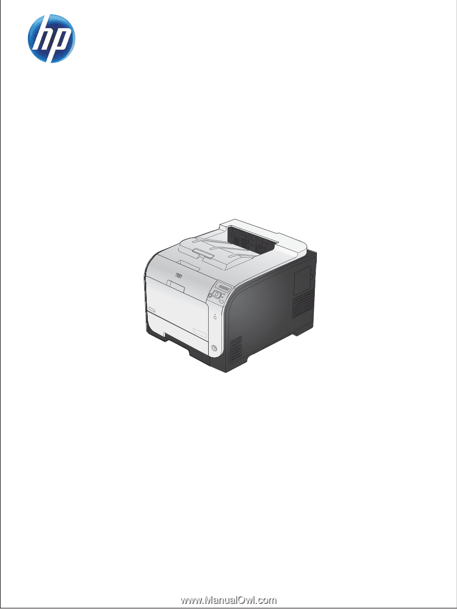
LASERJET PRO 300 COLOR
LASERJET PRO 400 COLOR
Service Manual
M351
M451