HP MSA70 HP StorageWorks 70 Modular Smart Array Enclosure maintenance and serv
HP MSA70 Manual
 |
View all HP MSA70 manuals
Add to My Manuals
Save this manual to your list of manuals |
HP MSA70 manual content summary:
- HP MSA70 | HP StorageWorks 70 Modular Smart Array Enclosure maintenance and serv - Page 1
HP StorageWorks 70 Modular Smart Array Enclosure maintenance and service guide This guide provides procedures and diagnostics needed for the maintenance and troubleshooting of the HP StorageWorks 70 Modular Smart Array Enclosure. March 2007 (Third Edition) Part Number 434895-003 - HP MSA70 | HP StorageWorks 70 Modular Smart Array Enclosure maintenance and serv - Page 2
to change without notice. The only warranties for HP products and services are set forth in the express warranty statements accompanying such products and services. Nothing herein should be construed as constituting an additional warranty. HP shall not be liable for technical or editorial errors - HP MSA70 | HP StorageWorks 70 Modular Smart Array Enclosure maintenance and serv - Page 3
Contents About this guide ...6 Intended audience...6 Prerequisites ...6 Document conventions and symbols ...6 HP technical support ...7 Product warranties...7 Subscription service ...8 HP websites...8 Documentation feedback ...8 Illustrated parts catalog ...9 System components ...9 Specifications - HP MSA70 | HP StorageWorks 70 Modular Smart Array Enclosure maintenance and serv - Page 4
Installing the access panel ...27 Hard drive blank ...27 Removing the hard drive blank ...27 Installing the hard drive blank ...27 Hot-plug hard drive ...28 Before you begin...28 Verifying component failure ...28 Removing the hard drive...29 Installing the hard drive ...30 Verifying component - HP MSA70 | HP StorageWorks 70 Modular Smart Array Enclosure maintenance and serv - Page 5
Riser board ...43 Before you begin...43 Verifying component failure ...43 Removing the riser board...43 Installing the riser board ...45 Verifying component replacement...45 Midplane ...45 Before you begin...45 Verifying component failure ...45 Removing the midplane ...46 Installing the midplane ... - HP MSA70 | HP StorageWorks 70 Modular Smart Array Enclosure maintenance and serv - Page 6
service guide provides information to help you: • Service the HP StorageWorks 70 Modular Smart Array Enclosure (MSA70) • Troubleshoot the MSA70 About this guide topics include: • Intended audience • Prerequisites • Document conventions and symbols • HP technical support • Subscription service • HP - HP MSA70 | HP StorageWorks 70 Modular Smart Array Enclosure maintenance and serv - Page 7
clarifying information or specific instructions. NOTE: Provides additional information. TIP: Provides helpful hints and shortcuts. HP technical support For worldwide technical support information, see the HP support website: http://www.hp.com/support. Before contacting HP, collect the following - HP MSA70 | HP StorageWorks 70 Modular Smart Array Enclosure maintenance and serv - Page 8
http://www.hp.com/support/manuals • http://www.hp.com/support/downloads Documentation feedback HP welcomes your feedback. To make comments and suggestions about product documentation, please send a message to [email protected]. All submissions become the property of HP. About this guide 8 - HP MSA70 | HP StorageWorks 70 Modular Smart Array Enclosure maintenance and serv - Page 9
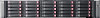
Illustrated parts catalog System components Item Description 1 Hard drives a) 36-GB SAS, 10,000 rpm b) 36-GB SAS, 15,000 rpm * c) 72-GB SAS, 10,000 rpm * d) 72-GB SAS, 15,000 rpm * e) 146-GB SAS 10,000 rpm * f) 60-GB SATA, 5,400 rpm * g) 80-GB SATA, 5,400 rpm * h) 160-GB SATA, 5,400 rpm * - HP MSA70 | HP StorageWorks 70 Modular Smart Array Enclosure maintenance and serv - Page 10
bezel N/A N/A *Not shown 1Mandatory-Parts for which customer self repair is mandatory. If you request HP to replace these parts, you will be charged for the travel and labor costs of this service. 2Optional-Parts for which customer self repair is optional. These parts are also designed for - HP MSA70 | HP StorageWorks 70 Modular Smart Array Enclosure maintenance and serv - Page 11
Specifications This chapter provides the environmental and enclosure specifications, and supported cable lengths for the MSA70. Environmental specifications Specification Value Temperature range Operating* 10°C to 35°C (50°F to 95°F) Maximum rate of change is 10º C/hr ( - HP MSA70 | HP StorageWorks 70 Modular Smart Array Enclosure maintenance and serv - Page 12
cables A 0.5-m (1.64-ft) SAS cable ships standard with the enclosure. HP recommends using the shortest cable possible, however, other supported cable lengths between SAS ports are 2 m (6.56 ft), 4 m (13.12 ft), and 6 m (19.69 ft). To acquire different lengths, contact the nearest authorized - HP MSA70 | HP StorageWorks 70 Modular Smart Array Enclosure maintenance and serv - Page 13
Identifying components This chapter identifies the components of the MSA70 and identifies and describes the status LEDs of the system: • Front panel components • Front panel LEDs • Rear panel components • Rear panel LEDs and buttons • Hard drive bay numbers • Hard drive LEDs • Hard drive LED - HP MSA70 | HP StorageWorks 70 Modular Smart Array Enclosure maintenance and serv - Page 14
Front panel LEDs Item Description Status 1 Heartbeat LED Green = System activity Off = No system activity 2 Fault LED Amber = Fault condition Off = No fault condition 3 UID button/LED Blue = Identified Blue flashing = Active remote management Off = No active remote management Rear - HP MSA70 | HP StorageWorks 70 Modular Smart Array Enclosure maintenance and serv - Page 15
Item Description 2 Fan 1 3 7-segment display board 4 SAS in connector 5 SAS out connector 6 I/O module 7 For future use 8 Fan 2 9 Power supply 2 Rear panel LEDs and buttons Item Description Status 1 I/O module LED Green = System activity Amber = Fault condition Off = No - HP MSA70 | HP StorageWorks 70 Modular Smart Array Enclosure maintenance and serv - Page 16
Item Description Status 7 Power supply LED Green = Power turned on and power supply functioning properly Amber = Standby (auxiliary power present) Blinking amber = Power to this power supply not present Off = One or more of the following conditions exists: • A/C power unavailable • Power - HP MSA70 | HP StorageWorks 70 Modular Smart Array Enclosure maintenance and serv - Page 17
Item Description 1 Fault/UID LED (amber/blue) 2 Online/activity LED (green) Hard drive LED combinations NOTE: Predictive failure alerts can occur only when the enclosure is connected to a Smart Array controller. Online/activity LED Fault/UID LED (green) (amber/blue) On, off, or flashing - HP MSA70 | HP StorageWorks 70 Modular Smart Array Enclosure maintenance and serv - Page 18
Diagnostics For more information, see the Management CD in the HP ProLiant Essentials Foundation Pack. Array Diagnostic Utility The Array Diagnostic Utility (ADU) collects information about array controllers and generates a list of detected problems. ADU can be accessed from the SmartStart CD or - HP MSA70 | HP StorageWorks 70 Modular Smart Array Enclosure maintenance and serv - Page 19
precautions or notices. Be sure to read and observe these statements. • Verifying component failure - Before replacing a component, confer with HP technical support to verify that the hardware component has failed and that you are authorized to replace it yourself. Verification procedures may - HP MSA70 | HP StorageWorks 70 Modular Smart Array Enclosure maintenance and serv - Page 20
day deliver options may be discussed with your support specialist. Replacement instructions are included in this document, in the spare kits,s and on the HP website. If further assistance is required, you can call the HP Technical Support Center and a support specialist will help you over the phone - HP MSA70 | HP StorageWorks 70 Modular Smart Array Enclosure maintenance and serv - Page 21
tools. • Use a portable field service kit with a folding static-dissipating work mat. If you do not have any of the suggested equipment for proper grounding, have an Authorized HP Reseller install the part. NOTE: For more information on static electricity or assistance with product installation - HP MSA70 | HP StorageWorks 70 Modular Smart Array Enclosure maintenance and serv - Page 22
Enclosed area contains no operator serviceable parts. To reduce the risk safety requirements and guidelines for manual material handling. • Get help in aligning the rails while the other two support the component. • Use caution when installing the instructions. Customer replaceable components 22 - HP MSA70 | HP StorageWorks 70 Modular Smart Array Enclosure maintenance and serv - Page 23
Fully extend the bottom stabilizers on the equipment. Ensure that the equipment is properly supported/braced when installing options and boards. • Be careful when sliding rack components health and safety requirements and guidelines for manually handling material. Customer replaceable components 23 - HP MSA70 | HP StorageWorks 70 Modular Smart Array Enclosure maintenance and serv - Page 24
be performed only by individuals who are qualified in servicing computer equipment, knowledgeable about the procedures and precautions, of repair specified in the procedures in the product documentation. All troubleshooting and repair procedures are detailed to allow only subassembly or module-level - HP MSA70 | HP StorageWorks 70 Modular Smart Array Enclosure maintenance and serv - Page 25
Removal and replacement procedures This chapter describes how to power up and power down the MSA70, and how to remove and replace the following MSA70 components: • Access panel • Hard drive blank • Hot-plug SAS or SATA hard drive • Hot-plug power supply • Hot-plug fan • I/O module • Front UID module - HP MSA70 | HP StorageWorks 70 Modular Smart Array Enclosure maintenance and serv - Page 26
1. Complete server hardware installation and cabling. See the server documentation. 2. Connect the SAS cables and power cords to the enclosure. 3. Press and hold the Power On/Standby button on the enclosure. Wait and observe the system power LED and fan modules. When the enclosure powers up, the - HP MSA70 | HP StorageWorks 70 Modular Smart Array Enclosure maintenance and serv - Page 27
WARNING! To reduce the risk of personal injury from hot surfaces, allow the drives and the internal system components to cool before touching them. CAUTION: To prevent damage to electrical components, properly ground the enclosure before beginning any installation procedure. Improper grounding can - HP MSA70 | HP StorageWorks 70 Modular Smart Array Enclosure maintenance and serv - Page 28
Hot-plug hard drive Before you begin CAUTION: • Before removing the failed component, make sure that you have the replacement part available. Removing a component impacts the airflow and cooling ability of the device. • Do not remove more than one component or blank from the enclosure at a time. - HP MSA70 | HP StorageWorks 70 Modular Smart Array Enclosure maintenance and serv - Page 29
spare, or not configured as part of an array. You can replace hard drives without powering down the system. However, before replacing a degraded drive: • Open HP SIM and inspect the Error Counter window for each physical drive in the same array to confirm that no other drives have any errors. (For - HP MSA70 | HP StorageWorks 70 Modular Smart Array Enclosure maintenance and serv - Page 30
2. Press the latch and slide it to the right to disengage the lever (1), and then open the lever (2). 3. Pull the hard drive out of the bay. Installing the hard drive To install the hard drive, reverse the removal procedure: 1. Slide the drive into the bay until it clicks, locking the drive into - HP MSA70 | HP StorageWorks 70 Modular Smart Array Enclosure maintenance and serv - Page 31
• Parts can be damaged by electrostatic discharge. Use proper anti-static protection. Verifying component failure Use the following methods to verify component failure: • Check the hot-plug power supply status LED: Green = Power turned on and power supply functioning properly Amber = Standby ( - HP MSA70 | HP StorageWorks 70 Modular Smart Array Enclosure maintenance and serv - Page 32
Hot-plug fan Before you begin CAUTION: • Before removing the failed component, make sure that you have the replacement part available. Removing a component impacts the airflow and cooling ability of the device. • Do not remove more than one component or blank from the enclosure at a time. Doing so - HP MSA70 | HP StorageWorks 70 Modular Smart Array Enclosure maintenance and serv - Page 33
Verifying component replacement After replacing the fan, check the fan status LED. I/O module Before you begin CAUTION: • Before removing the failed component, make sure that you have the replacement part available. Removing a component impacts the airflow and cooling ability of the device. • Do not - HP MSA70 | HP StorageWorks 70 Modular Smart Array Enclosure maintenance and serv - Page 34
3. Squeeze the lever (1) and pull it down (2). 4. Slide the I/O module out of the chassis (3). Installing the I/O module To install the I/O module: 1. Squeeze the lever and pull it down. 2. Slide the I/O module into the chassis until it clicks into place. 3. Connect SAS cables to the module. 4. - HP MSA70 | HP StorageWorks 70 Modular Smart Array Enclosure maintenance and serv - Page 35
Blue = Identified Blue flashing = Active remote management Off = No active remote management • Check the host log for errors. Removing the front UID module 1. Power down the enclosure: a. Power down any attached servers. See the server documentation. b. Press the Power On/Standby button on the - HP MSA70 | HP StorageWorks 70 Modular Smart Array Enclosure maintenance and serv - Page 36
Power on/off module Before you begin CAUTION: • Before removing the failed component, make sure that you have the replacement part available. Removing a component impacts the airflow and cooling ability of the device. • Do not remove more than one component or blank from the enclosure at a time. - HP MSA70 | HP StorageWorks 70 Modular Smart Array Enclosure maintenance and serv - Page 37
a. Loosen the front panel thumbscrews that secure the enclosure faceplate to the front of the rack. b. Disconnect the cabling and extend or remove the enclosure from the rack. 3. Remove the access panel: c. Lift the access panel latch (1). d. Slide the access panel to the rear (2). 4. Remove the - HP MSA70 | HP StorageWorks 70 Modular Smart Array Enclosure maintenance and serv - Page 38
6. Disconnect the cable from the power on/off module (1). 7. Loosen the thumbscrew on the module (2). 8. Slide the module back to remove it from the guide, and then lift it out of the chassis (3). Installing the power on/off module To install the power on/off module, reverse the removal procedure: - HP MSA70 | HP StorageWorks 70 Modular Smart Array Enclosure maintenance and serv - Page 39
Power UID module Before you begin CAUTION: • Before removing the failed component, make sure that you have the replacement part available. Removing a component impacts the airflow and cooling ability of the device. • Do not remove more than one component or blank from the enclosure at a time. Doing - HP MSA70 | HP StorageWorks 70 Modular Smart Array Enclosure maintenance and serv - Page 40
4. Disconnect the cable from the midplane (1). 5. Remove the T-15 screw securing the module to the chassis (2) and lift the module out of the chassis (3). CAUTION: Be careful not to accidentally drop the screw into the chassis when removing it from the module. Installing the power UID module To - HP MSA70 | HP StorageWorks 70 Modular Smart Array Enclosure maintenance and serv - Page 41
7-segment display board Before you begin CAUTION: • Before removing the failed component, make sure that you have the replacement part available. Removing a component impacts the airflow and cooling ability of the device. • Do not remove more than one component or blank from the enclosure at a time. - HP MSA70 | HP StorageWorks 70 Modular Smart Array Enclosure maintenance and serv - Page 42
4. Pull out the pin to release the board (1). 5. Put your finger inside the slot to slide the board out of the chassis (2). Installing the 7-segment display board To install the board, reverse the removal procedure: 1. Slide the board into the chassis and insert the pin to secure it. 2. Install the - HP MSA70 | HP StorageWorks 70 Modular Smart Array Enclosure maintenance and serv - Page 43
Riser board Before you begin CAUTION: • Before removing the failed component, make sure that you have the replacement part available. Removing a component impacts the airflow and cooling ability of the device. • Do not remove more than one component or blank from the enclosure at a time. Doing so - HP MSA70 | HP StorageWorks 70 Modular Smart Array Enclosure maintenance and serv - Page 44
4. Remove the 7-segment display board: a. Pull out the pin to release the board (1). b. Put your finger inside the slot to slide the board out of the chassis (2). 5. Loosen the thumbscrew (1) and lift the riser board out of the chassis (2). Removal and replacement procedures 44 - HP MSA70 | HP StorageWorks 70 Modular Smart Array Enclosure maintenance and serv - Page 45
Installing the riser board To install the riser board, reverse the removal procedure: 1. Attach the board to the chassis, securing it with the thumbscrew. 2. Install the access panel. 3. Insert the enclosure into the rack and power up the enclosure. Verifying component replacement After replacing - HP MSA70 | HP StorageWorks 70 Modular Smart Array Enclosure maintenance and serv - Page 46
Hard drive LED combinations Online/activity LED Fault/UID LED (green) (amber/blue) Flashing regularly Amber, flashing (1 Hz) regularly (1 Hz) Flashing regularly Off (1 Hz) Flashing irregularly Amber, flashing regularly (1 Hz) Flashing irregularly Off Off Steadily amber Off Amber, - HP MSA70 | HP StorageWorks 70 Modular Smart Array Enclosure maintenance and serv - Page 47
4. Remove the power supplies: a. Disconnect the power cord from the power supply. b. Press the latch inward (1) and pull the power supply out of the chassis (2). c. Repeat steps a and b for the redundant power supply. 5. Remove the fans: a. Press up on the lever (1). b. Slide the fan out of the - HP MSA70 | HP StorageWorks 70 Modular Smart Array Enclosure maintenance and serv - Page 48
6. Remove the I/O module: a. Disconnect any SAS cables connected to the I/O module. b. Squeeze the lever (1) and pull it down (2). c. Slide the I/O module out of the chassis (3). 7. Remove the I/O module blank: a. Squeeze the lever (1) and pull it down (2). b. Slide the I/O module blank out of the - HP MSA70 | HP StorageWorks 70 Modular Smart Array Enclosure maintenance and serv - Page 49
8. Remove the 7-segment display board: a. Pull out the pin to release the board (1). b. Put your finger inside the slot to slide the board out of the chassis (2). 9. Remove the riser board by loosening the thumbscrew (1) and lifting the board out of the chassis (2). Removal and replacement - HP MSA70 | HP StorageWorks 70 Modular Smart Array Enclosure maintenance and serv - Page 50
10. Disconnect the cables from the midplane. 11. Lift the lever up to disengage the midplane from the backplane (1). Removal and replacement procedures 50 - HP MSA70 | HP StorageWorks 70 Modular Smart Array Enclosure maintenance and serv - Page 51
12. Tilt the midplane up and remove it from the chassis (2). Installing the midplane To install the midplane, reverse the removal procedure: 1. Insert the midplane into the chassis, making sure that it is engaged with the backplane. Then press the lever down to secure it in the chassis and connect - HP MSA70 | HP StorageWorks 70 Modular Smart Array Enclosure maintenance and serv - Page 52
Verifying component failure Use the following methods to verify component failure: • Check the hard drive status LEDs as identified in the following table. Check with known good hard drives. • Check the host log for errors. Hard drive LED combinations Online/activity LED Fault/UID LED (green) ( - HP MSA70 | HP StorageWorks 70 Modular Smart Array Enclosure maintenance and serv - Page 53
b. Disconnect the cabling and extend or remove the enclosure from the rack. 3. Remove the access panel: a. Lift the access panel latch (1). b. Slide the access panel to the rear (2). 4. Remove the midplane: a. Remove the power supplies by disconnecting the power cords from the power supplies, - HP MSA70 | HP StorageWorks 70 Modular Smart Array Enclosure maintenance and serv - Page 54
c. Remove the I/O module by disconnecting any SAS cables connected to the I/O module, squeezing the lever (1), pulling the lever down (2), and then sliding the module out of the chassis. d. Remove the I/O module blank by squeezing the lever (1), pulling the lever down (2), and then sliding the blank - HP MSA70 | HP StorageWorks 70 Modular Smart Array Enclosure maintenance and serv - Page 55
e. Remove the 7-segment display board by pulling the pin out to release the board (1), and then putting your finger inside the slot to slide the board out of the chassis (2). f. Remove the riser board by loosening the thumbscrew (1) and lifting the board out of the chassis (2). Removal and - HP MSA70 | HP StorageWorks 70 Modular Smart Array Enclosure maintenance and serv - Page 56
g. Disconnect the cables from the midplane. h. Then lift the lever to disengage the midplane from the backplane (1), and then tilt the midplane up and remove it from the chassis (2). Removal and replacement procedures 56 - HP MSA70 | HP StorageWorks 70 Modular Smart Array Enclosure maintenance and serv - Page 57
5. Remove the screws on the backplane (1). 6. Tilt the backplane up from the bottom and lift it out of the chassis (2). Installing the backplane To install the backplane, reverse the removal procedure: 1. Insert the backplane into the chassis, securing it with the screw. 2. Install the midplane, - HP MSA70 | HP StorageWorks 70 Modular Smart Array Enclosure maintenance and serv - Page 58
"Smart Components for ROM Flash" in the MSA70 user guide. You can receive proactive support alerts, such as Customer Advisories, as well as updates on drivers, software, firmware, and customer replaceable components, via e-mail through HP Subscriber's Choice. Sign up for Subscriber's Choice at the - HP MSA70 | HP StorageWorks 70 Modular Smart Array Enclosure maintenance and serv - Page 59
Acronyms and abbreviations ACU Array Configuration Utility ADG Advanced Data Guarding (also known as RAID 6) ADU Array Diagnostics Utility IML Integrated Management Log MSA Modular Smart Array MSA70 Modular Smart Array 70 RAID redundant array of inexpensive (or independent) disks SAS serial attached - HP MSA70 | HP StorageWorks 70 Modular Smart Array Enclosure maintenance and serv - Page 60
UID unit identification WEBES Web-Based Enterprise Service Acronyms and abbreviations 60 - HP MSA70 | HP StorageWorks 70 Modular Smart Array Enclosure maintenance and serv - Page 61
Diagnostic Utility Array Diagnostic Utility 18 B backplane 51 installing 57 removing 52 buttons 13 C cables, supported 12 component failure, verifying 7-segment display board 41 backplane 52 front UID module 34 hard drive hot-plug fans 32 hot-plug power supplies 30 HP technical support 7 Index 61 - HP MSA70 | HP StorageWorks 70 Modular Smart Array Enclosure maintenance and serv - Page 62
39 riser board 43 riser board 43 installing 45 removing 43 S specifications 11 enclosure 11 environmental 11 subscription service 8 supported cables 12 system components 9 T technical support 7 tools 18 diagnostic 18 management 18 recommended 21 utilities 18 U utilities 18 W warnings 21 Index 62 - HP MSA70 | HP StorageWorks 70 Modular Smart Array Enclosure maintenance and serv - Page 63
warranties 7 warranty service, parts only 20 Index 63
-
 1
1 -
 2
2 -
 3
3 -
 4
4 -
 5
5 -
 6
6 -
 7
7 -
8
-
9
-
10
-
11
-
12
-
13
-
14
-
15
-
16
-
17
-
18
-
19
-
20
-
21
-
22
-
23
-
24
-
25
-
26
-
27
-
28
-
29
-
30
-
31
-
32
-
33
-
34
-
35
-
36
-
37
-
38
-
39
-
40
-
41
-
42
-
43
-
44
-
45
-
46
-
47
-
48
-
49
-
50
-
51
-
52
-
53
-
54
-
55
-
56
-
57
-
58
-
59
-
60
-
61
-
62
-
63
 |
 |

HP StorageWorks 70 Modular Smart Array
Enclosure
maintenance and service guide
This guide provides procedures and diagnostics needed for the maintenance and troubleshooting of the HP StorageWorks 70 Modular Smart
Array Enclosure.
March
2007 (
Third
Edition)
Part Number 434895-00
3