HP Mini 110-1001XX Service Guide
HP Mini 110-1001XX Manual
 |
View all HP Mini 110-1001XX manuals
Add to My Manuals
Save this manual to your list of manuals |
HP Mini 110-1001XX manual content summary:
- HP Mini 110-1001XX | Service Guide - Page 1
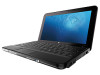
HP Mini 1101, HP Mini 110, HP Mini 110 by Studio Tord Boontje, and Compaq Mini 110 Maintenance and Service Guide - HP Mini 110-1001XX | Service Guide - Page 2
contained herein is subject to change without notice. The only warranties for HP products and services are set forth in the express warranty statements accompanying such products and services. Nothing herein should be construed as constituting an additional warranty. HP shall not be liable - HP Mini 110-1001XX | Service Guide - Page 3
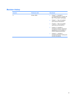
Revision history Revision A Publication date October 2009 Description ● Chapter 1 - Updated to incorporate Windows 7 and the HP Mini 110 by Studio Tord Boontje ● Chapter 3 - New and updated spare parts and descriptions ● Chapter 4 - New and updated spare parts and descriptions ● Chapter 6 - - HP Mini 110-1001XX | Service Guide - Page 4
iv Revision history - HP Mini 110-1001XX | Service Guide - Page 5
Safety warning notice WARNING! To reduce the possibility of heat-related injuries or of overheating the device, do not place the device directly on your lap or obstruct the device air vents. Use the device only on a hard, flat surface. Do not allow another hard surface, such as an adjoining optional - HP Mini 110-1001XX | Service Guide - Page 6
vi Safety warning notice - HP Mini 110-1001XX | Service Guide - Page 7
side components ...11 Left-side components ...12 Display components ...13 Bottom components ...14 Wireless antennas ...15 3 Illustrated parts catalog Service tag ...16 Device major components ...17 Display assembly components ...25 Mass storage devices ...27 Miscellaneous parts ...28 Sequential part - HP Mini 110-1001XX | Service Guide - Page 8
Equipment guidelines 41 Component replacement procedures 42 Service tag ...42 Device feet ...43 Battery ...44 SIM ...45 Memory module ...46 Keyboard ...48 RTC battery ...53 Mass storage devices ...54 Hard drive ...55 Solid- - HP Mini 110-1001XX | Service Guide - Page 9
System interrupt specifications ...93 System I/O address specifications ...94 System memory map specifications 96 7 Screw listing Phillips PM1.5×1.0 screw ...97 Phillips PM2.0×3.0 screw ...99 Phillips PM2.0×3.0 captive screw ...101 Phillips PM2.0×4.0 screw ...102 Phillips PM2.0×5.0 screw ...103 - HP Mini 110-1001XX | Service Guide - Page 10
Creating a set of recovery discs 119 Performing a recovery ...120 Recovering using the recovery discs 120 Recovering using the partition on the hard drive (select models only 120 Windows Vista backup and recovery 122 Backing up your information 122 Performing a recovery ...123 Using the Windows - HP Mini 110-1001XX | Service Guide - Page 11
1 Product description Category Description HP Mini 1101 Product name HP Mini 1101 √ HP Mini 110 HP Mini 110 by Studio Tord Boontje Compaq Mini 110 Processor Intel® Atom™ N280 1.66-GHz √ processor, 512-KB Level 2 cache, 533-MHz front-side bus (FSB) Intel Atom N270 1.6-GHz √ processor, - HP Mini 110-1001XX | Service Guide - Page 12
by computers with Windows® XP Home SP3, ultra low-cost personal computer (ULCPC) edition installed. 250-GB, 5400-RPM √ NOTE: Not supported by computers with Windows XP Home SP3, ultra low-cost personal computer (ULCPC) edition installed. 160-GB, 7200-RPM 160-GB, 5400-RPM √ Optical drive - HP Mini 110-1001XX | Service Guide - Page 13
installed. External media cards Digital Media Slot (consumer √ models) or Media Card Reader (commercial models) with push- push technology supporting: ● Memory Stick (MS) ● Memory Stick Pro (MSP) ● MultiMediaCard (MMC) ● Secure Digital (SDHC) Memory Card ● xD-Picture Card (XD) Internal - HP Mini 110-1001XX | Service Guide - Page 14
) √ battery (2.55-Ah, 28-Wh), 3-hour target life Security Supports HP Kensington √ Security Lock Operating system Preinstalled: Windows 7 Basic 32 Vista® Business 32 √ (with XP Pro image) HP Mobile Mi Serviceability End-user replaceable parts: AC adapter √ Battery (system) √ Hard - HP Mini 110-1001XX | Service Guide - Page 15
2 External component identification Components included with the device may vary by region and model. The illustrations in this chapter identify the standard features on most device models. Top components TouchPad Component (1) Left TouchPad button (2) TouchPad (3) TouchPad scroll zone (4) - HP Mini 110-1001XX | Service Guide - Page 16
Light Component Caps lock light Description On: Caps lock is on. 6 Chapter 2 External component identification - HP Mini 110-1001XX | Service Guide - Page 17
Keys NOTE: Refer to the illustration that most closely matches your computer. Component (1) (2) (3) (4) Function keys fn key Windows® logo key Windows applications key Description Execute frequently used system functions when pressed in combination with the fn key. Executes frequently used system - HP Mini 110-1001XX | Service Guide - Page 18
Component (1) (2) (3) (4) Function keys fn key Home key Program Switcher key Description Execute frequently used system functions when pressed in combination with the fn key. Executes frequently used system functions when pressed in combination with a function key. Returns to the Home Screen. - HP Mini 110-1001XX | Service Guide - Page 19
Front components Component (1) Power light (2) Power switch (3) Drive light (4) Battery light Description ● On: The device is on. ● Blinking: The device is in the Sleep state (Windows Vista) or Standby (Windows XP or Mobile Mi). ● Off: The device is off or in Hibernation. ● When the device - HP Mini 110-1001XX | Service Guide - Page 20
Component (5) Wireless light (6) Wireless switch Description ● Blue: An integrated wireless device, such as a wireless local area network (WLAN) device, is on. ● Amber: All wireless devices are off. Turns the wireless feature on or off, but does not establish a wireless connection. NOTE: A - HP Mini 110-1001XX | Service Guide - Page 21
-side components Component Description (1) USB ports (2) Connect optional USB devices. (2) Digital Media Slot (consumer models) or Media Card Supports the following optional digital card formats: Reader (commercial models) ● Memory Stick (MS) ● Memory Stick Pro (MSP) ● MultiMediaCard (MMC - HP Mini 110-1001XX | Service Guide - Page 22
Left-side components Component (1) Security cable slot (2) Power connector (3) AC adapter light (4) Vent (5) USB port (6) Audio-out (headphone) jack/Audio-in (microphone) jack Description Attaches an optional security cable to the device. NOTE: The security cable is designed to act as - HP Mini 110-1001XX | Service Guide - Page 23
Display components Component (1) Speakers (2) (2) Internal display switch (3) Webcam (4) Webcam light (5) Internal microphone Description Produce sound. Turns off the display if the display is closed while the power is on. NOTE: The display switch is not visible from the outside of the - HP Mini 110-1001XX | Service Guide - Page 24
Bottom components Component (1) Battery bay (2) Battery release latches (2) (3) Vent (4) Memory module compartment Description Holds the battery. Release the battery from the battery bay. Enables airflow to cool internal components. NOTE: The device fan starts up automatically to cool - HP Mini 110-1001XX | Service Guide - Page 25
Wireless antennas Component Description (1) WWAN antennas (2) (select models only)* Send and receive wireless signals to communicate with wireless wide-area networks (WWANs). (2) WLAN antennas (2)* NOTE: This option is not available on computers with Mobile Mi installed. Send and receive - HP Mini 110-1001XX | Service Guide - Page 26
about the product's hardware components. The part number helps a service technician to determine what components and parts are needed. (4) : This is the alphanumeric identifier used to locate documents, drivers, and support for the device. (5) Warranty period: This number describes the duration of - HP Mini 110-1001XX | Service Guide - Page 27
Device major components Item (1) Description Spare part number Display assembly (includes 1 webcam, 1 microphone, 1 speaker box, and 2 WLAN antenna transceivers/cables; WWAN on select models only) See Display assembly components on page 25 for a comprehensive list of display assembly spare - HP Mini 110-1001XX | Service Guide - Page 28
Item (2) Description ● 10.1-inch, standard-definition, AntiGlare display assembly (includes WWAN) ● 10.1-inch, standard-definition, AntiGlare display assembly ● 10.1-inch, WSVGA, AntiGlare display assembly (includes WWAN) For use with pink HP models only ● 10.1-inch, high-definition, AntiGlare - HP Mini 110-1001XX | Service Guide - Page 29
Item Description ● For use with international models ● For use only in Israel ● For use only in Italy ● For use only in Japan ● For use only in Latin America ● For use only in Portugal ● For use only in Russia ● For use only in Saudi Arabia ● For use only in South Korea ● For use only in Spain ● - HP Mini 110-1001XX | Service Guide - Page 30
Item Description ● For use only in Greece ● For use only in Hungary ● For use with international models ● For use only in Israel ● For use only in Italy ● For use only in Japan ● For use only in Latin America ● For use only in Portugal ● For use only in Russia ● For use only in Saudi Arabia ● For - HP Mini 110-1001XX | Service Guide - Page 31
Item (3) (4a) (4b) (5) (6) (7) (8) Description Spare part number ● For use only in Portugal ● For use only in Russia ● For use only in Saudi Arabia ● For use only in South Korea ● For use only in Spain ● For use only in Switzerland ● For use only in Taiwan ● For use only in Thailand ● For use - HP Mini 110-1001XX | Service Guide - Page 32
Item (9a) (9b) (9c) (10) Description Spare part number Power switch and wireless switch actuators Memory module compartment cover Bezel for Digital Media Slot (consumer models) or Media Card Reader (commercial models) Wireless modules WLAN module WLAN/Bluetooth combination module 575920-001 - HP Mini 110-1001XX | Service Guide - Page 33
Item (11) (12) (13) Description Spare part number ● For use in Afghanistan, Albania, Algeria, Andorra, Angola, Antigua and Barbuda, 504593-004 Argentina, Armenia, Aruba, Australia, Austria, Azerbaijan, the Bahamas, Bahrain, Bangladesh, Barbados, Belarus, Belgium, Belize, Benin, Bermuda, Bhutan - HP Mini 110-1001XX | Service Guide - Page 34
Item (14) (15) (16) Description Spare part number Includes Intel Atom N280 1.66-GHz processor, 512-KB Level 2 cache, 533-MHz front-side bus 579569-001 (FSB) For use on the following model numbers only: HP: 110-1100 - 110-1199 and Compaq: 110c-1100 - 110-1199 Includes Intel Atom N270 1.6-GHz - HP Mini 110-1001XX | Service Guide - Page 35
Display assembly components Item Description Spare part number (1) Hinge covers (2) Display bezel 537617-001 For use with HP Mini 1101 and HP Mini 110 only For use with HP Mini 110 by Studio Tord Boontje models only For use with Compaq Mini 110 only (3) Display Hinge Kit 537650-001 581324-001 - HP Mini 110-1001XX | Service Guide - Page 36
Item Description (7b) WLAN antennas ● For use with high-definition and standard-definition display panels only ● For use with WSVGA display panels only (8) Microphone assembly (9) WWAN antennas (not available on computers with Mobile Mi installed.) (10) Display enclosure (includes logo) For use with - HP Mini 110-1001XX | Service Guide - Page 37
Mass storage devices NOTE: Each hard drive spare part kit and solid-state drive spare part kit includes a cable and bracket. Item Description (1) Hard drive (select models only) 320-GB, 5400-RPM 250-GB, 5400-RPM 160-GB, 7200-RPM 160-GB, 5400-RPM Hard Drive Hardware Kit (not illustrated) (2) Solid- - HP Mini 110-1001XX | Service Guide - Page 38
Miscellaneous parts Description 30-W UMA AC adapter Bluetooth® adapter High-definition video decoder Power cords For use in Argentina For use in Australia For use in Brazil For use in Denmark For use in Europe For use in India For use in Israel For use in Italy For use in Japan For use in North - HP Mini 110-1001XX | Service Guide - Page 39
Sequential part number listing Spare part number Description 483377-002 HP un2400 Mobile Broadband Module (select models only) 483377-003 HP un2400 Mobile Broadband Module for use with Verizon Wireless only (select models only) 490371-001 Power cord for use in North America 490371-011 Power - HP Mini 110-1001XX | Service Guide - Page 40
Spare part number Description 518436-001 Broadcom 4312 802.11/b/g/n WLAN module for use in Canada, the Cayman Islands, Guam, Puerto Rico, the U.S. Virgin Islands, and the United States 518436-002 Broadcom 4312 802.11/b/g/n WLAN module for use in Afghanistan, Albania, Algeria, Andorra, Angola, - HP Mini 110-1001XX | Service Guide - Page 41
Spare part number Description 535689-A41 Keyboard for use only in Europe on black and blue models with Windows operating system installed 535689-AB1 Keyboard for use only in Taiwan on black and blue models with Windows operating system installed 535689-AD1 Keyboard for use only in South Korea on - HP Mini 110-1001XX | Service Guide - Page 42
Spare part number 537627-001 537634-001 537635-001 537637-001 537638-001 537639-001 537640-001 537641-001 537642-001 537643-001 537644-001 537645-001 537646-001 537650-001 537651-001 537653-001 537654-001 537655-001 537656-001 537657-001 537658-001 537660-001 537662-001 537663-001 537664-001 537665- - HP Mini 110-1001XX | Service Guide - Page 43
Spare part number Description 537953-061 Keyboard for use with white HP models only in Italy 537953-071 Keyboard for use with white HP models only in Spain 537953-121 Keyboard for use with white HP models only in French Canada 537953-131 Keyboard for use with white HP models only in Portugal - HP Mini 110-1001XX | Service Guide - Page 44
Spare part number Description 537954-201 Keyboard for use with pink HP models only in Brazil 537954-211 Keyboard for use with pink HP models only in Hungary 537954-221 Keyboard for use with pink HP models only in the Czech Republic 537954-251 Keyboard for use with pink HP models only in Russia - HP Mini 110-1001XX | Service Guide - Page 45
Spare part number 574246-001 574670-001 575920-001 578237-001 579568-001 579569-001 579570-001 579571-001 579576-001 579604-001 579606-001 579608-001 579610-001 579612-001 579614-001 579615-001 579626-001 581323-001 581324-001 581325-001 581326-001 590669-001 591398-001 591612-001 Description HP - HP Mini 110-1001XX | Service Guide - Page 46
Spare part number 591647-001 591648-001 591649-001 591650-001 592624-161 592625-161 Description 10.1-inch, high-definition, AntiGlare display assembly (includes WWAN) for use with blue HP models only (includes 1 webcam, 1 microphone, 1 speaker box, and 2 WLAN antenna transceivers/cables) 10.1-inch, - HP Mini 110-1001XX | Service Guide - Page 47
plastic parts. Use care when handling the plastic parts. Apply pressure only at the points designated in the maintenance instructions. Cables and connectors CAUTION: When servicing the device, be sure that cables are placed in their proper locations during the reassembly process. Improper cable - HP Mini 110-1001XX | Service Guide - Page 48
Drive handling CAUTION: Drives are fragile components that must be handled with care. To prevent damage to the device, damage to a drive, or loss of information, observe these precautions: Before removing or inserting a hard drive, shut down the device. If you are unsure whether the device is off or - HP Mini 110-1001XX | Service Guide - Page 49
Grounding guidelines Electrostatic discharge damage Electronic components are sensitive to electrostatic discharge (ESD). Circuitry design and structure determine the degree of sensitivity. Networks built into many integrated circuits provide some protection, but in many cases, ESD contains enough - HP Mini 110-1001XX | Service Guide - Page 50
material. ● Use a wrist strap connected to a properly grounded work surface and use properly grounded tools and equipment. ● Use conductive field service tools, such as cutters, screwdrivers, and vacuums. ● When fixtures must directly contact dissipative surfaces, use fixtures made only of static - HP Mini 110-1001XX | Service Guide - Page 51
with ground cords of one megohm resistance ● Static-dissipative tables or floor mats with hard ties to the ground ● Field service kits ● Static awareness labels ● Material-handling packages ● Nonconductive plastic bags, tubes, or boxes ● Metal tote boxes ● Electrostatic voltage levels and - HP Mini 110-1001XX | Service Guide - Page 52
about the product's hardware components. The part number helps a service technician to determine what components and parts are needed. (4) : This is the alphanumeric identifier used to locate documents, drivers, and support for the device. (5) Warranty period: This number describes the duration of - HP Mini 110-1001XX | Service Guide - Page 53
Device feet The device feet are adhesive-backed rubber pads, tethered to the base enclosure. Description Rubber Kit Spare part number 537618-001 Component replacement procedures 43 - HP Mini 110-1001XX | Service Guide - Page 54
Battery Description 6-cell lithium-polymer (Li-Pol) battery (2.55-Ah, 55-Wh) 3-cell lithium-polymer (Li-Pol) battery (2.55-Ah, 28-Wh) Spare part number 537627-001 537626-001 Before disassembling the device, follow these steps: 1. Shut down the device. If you are unsure whether the device is off or - HP Mini 110-1001XX | Service Guide - Page 55
SIM NOTE: This section applies only to device models with WWAN capability. NOTE: If there is a SIM inserted in the SIM slot, it must be removed before disassembling the computer. Be sure that the SIM is reinserted in the SIM slot after reassembling the computer. Before removing the SIM, follow - HP Mini 110-1001XX | Service Guide - Page 56
Memory module Description Memory module (PC2-5300, 533-MHz, DDR2) 512-MB (for use in HP Mini 110 and Compaq Mini 110 only) 1024-MB 2048-MB Spare part number 537663-001 537664-001 537665-001 Before removing the memory module, follow these steps: 1. Shut down the device. If you are unsure whether - HP Mini 110-1001XX | Service Guide - Page 57
4. Remove the memory module (2) by pulling the module away from the slot at an angle. NOTE: Memory modules are designed with a notch (3) to prevent incorrect insertion into the memory module slot. Reverse this procedure to install a memory module. Component replacement procedures 47 - HP Mini 110-1001XX | Service Guide - Page 58
Keyboard Description For use only on black and blue models with Windows operating system installed ● For use only in Brazil ● For use only in the Czech Republic ● For use only in Europe ● For use only in Finland, Norway, and Sweden ● For use only in France ● For use only in French Canada ● For use - HP Mini 110-1001XX | Service Guide - Page 59
Description ● For use only in Thailand ● For use only in the United States For use on pink models only ● For use only in Bosnia, Croatia, Montenegro, Serbia, and Slovenia ● For use only in Brazil ● For use only in the Czech Republic ● For use only in Europe ● For use only in Finland, Norway, and - HP Mini 110-1001XX | Service Guide - Page 60
Description ● For use only in Finland, Norway, and Sweden ● For use only in France ● For use only in French Canada ● For use only in Germany ● For use only in Greece ● For use only in Hungary ● For use with international models ● For use only in Israel ● For use only in Italy ● For use only in Japan - HP Mini 110-1001XX | Service Guide - Page 61
Remove the keyboard: 1. Remove the 3 Phillips SP2.0×3.0 screws that secure the keyboard to the device. 2. Turn the device right-side up, and then open the display as far as possible. 3. Turn the device upside down, and locate the keyboard release access on the bottom of the computer, inside the - HP Mini 110-1001XX | Service Guide - Page 62
6. Slide the keyboard back until its top edge rests on the display assembly (2). 7. Release the zero insertion force (ZIF) connector (1) to which the keyboard cable is attached. 8. Disconnect the cable (2), and then remove the keyboard. 9. Remove the keyboard. Reverse this procedure to install the - HP Mini 110-1001XX | Service Guide - Page 63
RTC battery Description RTC battery Spare part number 537616-001 Before removing the real-time clock (RTC) battery, follow these steps: 1. Shut down the device. If you are unsure whether the device is off or in Hibernation, turn the device on, and then shut it down through the operating system. 2. - HP Mini 110-1001XX | Service Guide - Page 64
Mass storage devices NOTE: Each hard drive spare part kit and solid-state drive spare part kit includes a cable and bracket. Description Hard drive (select models only) 320-GB, 5400-RPM 250-GB, 5400-RPM 160-GB, 7200-RPM 160-GB, 5400-RPM Hard Drive Hardware Kit Solid-state drive 64-GB 32-GB 16-GB 8- - HP Mini 110-1001XX | Service Guide - Page 65
2. Use the Mylar tab to slide the assembly to the left (3) to disconnect it, and remove the assembly (4). Continue with one of the following sections for hard drive or solid-state drive replacement. Hard drive 1. Remove the 4 Phillips SP3.0×4.0 screws (1) that secure the hard drive bracket to the - HP Mini 110-1001XX | Service Guide - Page 66
2. Lift the solid-state drive (2) to remove it. Reverse this procedure to install a solid-state drive. 56 Chapter 4 Removal and replacement procedures - HP Mini 110-1001XX | Service Guide - Page 67
Top cover Description Top cover (includes TouchPad) ● For use with black and blue models only ● For use with pink HP models only ● For use with white HP models only ● For use with HP Mini 110 by Studio Tord Boontje models only Spare part number 537622-001 537625-001 537624-001 579615-001 Before - HP Mini 110-1001XX | Service Guide - Page 68
4. Turn the device right-side up, with the front toward you. 5. Open the device as far as possible. 6. Remove the 8 Phillips PM2.5×7.0 screws that secure the top cover to the base enclosure. 7. Lift the inside edge of the top cover (1) and swing it up. Then slide the top cover back slightly to rest - HP Mini 110-1001XX | Service Guide - Page 69
9. Disconnect the TouchPad button board cable (2) from the system board, and then remove the top cover. Reverse this procedure to install the top cover. Component replacement procedures 59 - HP Mini 110-1001XX | Service Guide - Page 70
WLAN module Description Spare part number WLAN/Bluetooth combination module 575920-001 Broadcom 4312 802.11/b/g/n WLAN module For use in Canada, the Cayman Islands, Guam, Puerto Rico, the U.S. Virgin Islands, and the United States 518436-001 For use in Afghanistan, Albania, Algeria, Andorra, - HP Mini 110-1001XX | Service Guide - Page 71
. If you replace the module and then receive a warning message, remove the module to restore device functionality, and then contact technical support through Help and Support. Before removing the WLAN module, follow these steps: 1. Shut down the device. If you are unsure whether the device is off - HP Mini 110-1001XX | Service Guide - Page 72
your country or region. If you replace the module and then receive a warning message, remove the module to restore device functionality, and then contact technical support. Before removing the WWAN module, follow these steps: 1. Shut down the device. If you are unsure whether the device is off or in - HP Mini 110-1001XX | Service Guide - Page 73
3. Remove the WWAN module (3) by pulling the module away from the slot at an angle. Reverse this procedure to install the WWAN module. Component replacement procedures 63 - HP Mini 110-1001XX | Service Guide - Page 74
USB/audio board Description Spare part number USB/audio board (includes cable) For use on the following model numbers only: HP: 110-1000 - 110-1099 and Compaq: 110c-1000 537614-001 - 110-1099 For use on the following model numbers only: HP: 110-1100 - 110-1199 and Compaq: 110c-1100 581325-001 - - HP Mini 110-1001XX | Service Guide - Page 75
Reverse this procedure to install the USB/audio board. Component replacement procedures 65 - HP Mini 110-1001XX | Service Guide - Page 76
Power/battery pass-through board Description Spare part number Power/battery pass-through board For use on the following model numbers only: HP: 110-1000 - 110-1099 and Compaq: 110c-1000 537615-001 - 110-1099 For use on the following model numbers only: HP: 110-1100 - 110-1199 and Compaq: 110c- - HP Mini 110-1001XX | Service Guide - Page 77
3. Remove the power/battery pass-through board (3). Reverse this procedure to install the power/battery pass-through board. Component replacement procedures 67 - HP Mini 110-1001XX | Service Guide - Page 78
Fan Description Fan Spare part number 537613-001 NOTE: To properly ventilate the device, allow at least a 7.6-cm (3-inch) clearance on the left side of the device. The device uses an electric fan for ventilation. The fan is controlled by a temperature sensor and is designed to turn on - HP Mini 110-1001XX | Service Guide - Page 79
3. Remove the fan (3). Reverse this procedure to install the fan. Component replacement procedures 69 - HP Mini 110-1001XX | Service Guide - Page 80
Heat sink assembly Description Heat sink assembly (includes replacement thermal material) Spare part number 537619-001 Before removing the heat sink assembly, follow these steps: 1. Shut down the device. If you are unsure whether the device is off or in Hibernation, turn the device on, and then - HP Mini 110-1001XX | Service Guide - Page 81
2. Remove the heat sink assembly (2). NOTE: Due to the adhesive quality of the thermal material located between the heat sink assembly and system board components, it may be necessary to move the heat sink assembly from side to side to detach the assembly. NOTE: The thermal material must be - HP Mini 110-1001XX | Service Guide - Page 82
System board Description Spare part number System board (includes processor and replacement thermal material) Includes Intel Atom N280 1.66-GHz processor, 512-KB Level 2 cache, 533-MHz front-side bus (FSB) 571370-001 For use on the following model numbers only: HP: 110-1000 - 110-1099 and Compaq - HP Mini 110-1001XX | Service Guide - Page 83
Remove the system board: 1. Release the tape securing the WWAN antennas (1). 2. Disconnect the following cables from the system board: (2) Display panel cable (3) Microphone cable (4) Speaker cable (5) WLAN cables (6) WWAN cables (select models only) 3. Remove the 2 Phillips PM1.5×2.0 screws (1) - HP Mini 110-1001XX | Service Guide - Page 84
5. Remove the 3 Phillips PM2.5×5.0 screws that secure the system board to the base enclosure. 6. Grasp the system board at the midpoint of the left side (1), and lift it up. 7. Pull the system board (2) out to the left at an angle to remove it. 8. Remove the system board. Reverse the procedure to - HP Mini 110-1001XX | Service Guide - Page 85
Display assembly NOTE: Each display assembly spare part kit includes 1 webcam, 1 microphone, 1 speaker box, and 2 WLAN antenna transceivers/cables; WWAN on select models only. Description For use with black HP models only ● 10.1-inch, high-definition, AntiGlare display assembly (includes WWAN) ● 10 - HP Mini 110-1001XX | Service Guide - Page 86
Description Display Hinge Kit (Includes left and right display panel hinges) Speaker assembly (includes left and right cables) Display panel 10.1-inch high-definition AntiGlare 10.1-inch standard-definition AntiGlare 10.1-inch WSVGA AntiGlare Webcam module Display Cable Kit (includes display/webcam - HP Mini 110-1001XX | Service Guide - Page 87
Display panel cable (3) Microphone cable (4) Speaker cable (5) WLAN cables (6) WWAN cables (select models only) CAUTION: Support the display assembly when removing the following screws. Failure to support the display assembly can result in damage to the display assembly and other device components - HP Mini 110-1001XX | Service Guide - Page 88
4. Remove the display assembly (3). 5. If it is necessary to replace the display bezel, perform the following steps: a. Remove the display hinge covers (1). b. Flex the inside edges of the top and bottom (2), and then the left and right sides (3) of the display bezel until the bezel disengages from - HP Mini 110-1001XX | Service Guide - Page 89
6. If it is necessary to replace the display panel, perform the following steps: a. Remove the 7 Phillips PM2.0×3.0 screws that secure the display panel to the display enclosure. b. Lift the display panel up from the display enclosure (1). c. Disconnect the webcam cable (2) from the system board (2) - HP Mini 110-1001XX | Service Guide - Page 90
b. Remove the speaker assembly (2). 8. If it is necessary to replace the display hinges, perform the following steps: a. Remove the 2 Phillips PM2.0×3.0 screws (1) that secure each hinge to the display enclosure. b. Remove the hinges (2). 9. If it is necessary to replace the display panel cable, - HP Mini 110-1001XX | Service Guide - Page 91
b. Disconnect the display panel cable (2). 10. If it is necessary to replace the webcam module, perform the following steps: a. Disconnect the webcam cable (1) from the webcam. b. Remove the webcam (2). 11. If it is necessary to replace the microphone receiver, perform the following steps: a. - HP Mini 110-1001XX | Service Guide - Page 92
b. Pull the receiver through the tabs (2), and remove the microphone receiver (3). 12. If it is necessary to replace the wireless antenna transceivers and cables, detach the cables from the adhesive (1) that secures them to the display enclosure, and then remove the cables (2). Reverse this - HP Mini 110-1001XX | Service Guide - Page 93
Your change goes into effect immediately. Navigating and selecting in the Setup Utility Because the Setup Utility is not operating system-based, it does not support the TouchPad. Navigation and selection are by keystroke. ● To choose a menu or a menu item, use the arrow keys. ● To choose an item in - HP Mini 110-1001XX | Service Guide - Page 94
● To select an item, press enter. ● To close a text box or return to the menu display, press esc. ● To display additional navigation and selection information while the Setup Utility is open, press f1. Displaying system information The following procedure explains how to display system information - HP Mini 110-1001XX | Service Guide - Page 95
this section provide an overview of Setup Utility options. NOTE: Some of the Setup Utility menu items listed in this chapter may not be supported by your device. Main menu Select System information To do this ● View and change the system time and date. ● View identification information about the - HP Mini 110-1001XX | Service Guide - Page 96
Diagnostics menu Select Hard Disk Self Test (select models only) Memory Test To do this Run a comprehensive self-test on the hard drive. Run a diagnostic test on the system memory. 86 Chapter 5 Setup Utility - HP Mini 110-1001XX | Service Guide - Page 97
6 Specifications Device specifications Metric Dimensions Depth 16.67 cm Width 26.17 cm Height 2.52 cm Weight 10.1-in. LCD, equipped with a 3-cell battery, hard drive, 1-GB 1.11 kg memory, WLAN module, and 2 wireless antennas 10.1-in. LCD, equipped with a 3-cell battery,solid-state drive, - HP Mini 110-1001XX | Service Guide - Page 98
10.1-inch, AntiGlare display specifications Dimensions Height Width Diagonal Number of colors Contrast ratio Brightness Pixel resolution Pitch Format Configuration Backlight Character display Total power consumption Viewing angle Metric U.S. 23.45 cm 14.30 cm 25.55 cm 262,144 400:1 (typical) 200 - HP Mini 110-1001XX | Service Guide - Page 99
10.1-inch, WSVGA, AntiGlare display specifications Dimensions Height Width Diagonal Number of colors Contrast ratio Brightness Pixel resolution Pitch Format Configuration Backlight Character display Total power consumption Viewing angle Metric U.S. 12.53 cm 22.27 cm 25.55 cm 262,144 400:1 ( - HP Mini 110-1001XX | Service Guide - Page 100
referring to hard drive storage capacity. Actual accessible capacity is less. Actual drive specifications may differ slightly. NOTE: Certain restrictions and exclusions apply. Contact technical support for details. 90 Chapter 6 Specifications - HP Mini 110-1001XX | Service Guide - Page 101
Solid-state drive specifications Performance Transfer modes supported Sustained read Sustained write Characteristics Interface MLC NAND flash capacity Electrical specifications DC supply voltage Standby current Active current Environmental specifications Operating temperature Storage temperature - HP Mini 110-1001XX | Service Guide - Page 102
System DMA specifications Hardware DMA DMA0 DMA1* DMA2* DMA3 DMA4 System function Not applicable Not applicable Not applicable Not applicable Direct memory access controller 92 Chapter 6 Specifications - HP Mini 110-1001XX | Service Guide - Page 103
System interrupt specifications Hardware IRQ IRQ0 IRQ1 IRQ8 IRQ9 * IRQ12 IRQ13 IRQ14 IRQ15 IRQ16 IRQ17 IRQ18 IRQ19 IRQ23 * Default configuration System function System timer Standard 101-/102-Key or Microsoft® Natural PS/2 Keyboard System CMOS/real-time clock Microsoft ACPI-compliant system - HP Mini 110-1001XX | Service Guide - Page 104
System I/O address specifications I/O address (hex) 000 - 00F 000 - CF7 010 - 01F 020 - 021 022 - 03F 040 - 043 044 - 05F 060 - 060 061 - 061 062 - 062 063- 063 064 - 064 065 - 065 066 - 066 067 - 06F 070 - 071 072 - 07F 080 - 080 081 - 083 084 - 086 087 - 087 088 - 088 089 - 08B 08C - 08E 08F - - HP Mini 110-1001XX | Service Guide - Page 105
I/O address (hex) 279 - 279 3B0 - 3BB 3C0 - 3DF 3F6 - 3F6 400 - 41F 480 - 4BF 4D0 - 4D1 500 - 501 800 - 87F A79 - A79 0D00 - FFFF D480 - D49F D800 - D81F D880 - D89F DC00 - DC1F DC80 - DC87 E000 - EFFF FFA0 - FFAF System function (shipping configuration) ISAPNP Read Data Port Mobile Intel® 945 - HP Mini 110-1001XX | Service Guide - Page 106
System memory map specifications Memory address 00000000 - 0009FFFF 000A0000 - 000BFFFF 000A0000 - 000BFFFF 000C0000 - 000CFFFF 000D0000 - 000DFFFF 000E0000 - 000FFFFF 00100000 - 3F7FFFFF 3F800000 - DFFFFFFF D0000000 - DFFFFFFF E0000000 - E3FFFFFF E4000000 - FED8FFFF FE880000 - FE8FFFFF FE937C00 - - HP Mini 110-1001XX | Service Guide - Page 107
7 Screw listing This section provides specification and reference information for the screws and screw locks used in the device. All screws listed in this section are available in the Screw Kit, spare part number 537620-001; or in the Display Screw Kit, spare part number 538510-001. Phillips PM1 - HP Mini 110-1001XX | Service Guide - Page 108
Where used: Two screws that secure the power and wireless switch actuators to the base enclosure 98 Chapter 7 Screw listing - HP Mini 110-1001XX | Service Guide - Page 109
Phillips PM2.0×3.0 screw Color Black Quantity 20 Length 3.0 mm Thread 2.0 mm Head diameter 4.0 mm Where used: 3 screws that secure the keyboard to the device Where used: Four screws that secure the solid-state drive to the bracket Phillips PM2.0×3.0 screw 99 - HP Mini 110-1001XX | Service Guide - Page 110
Where used: Seven screws that secure the display panel to the display enclosure Where used: Three screws that secure the speaker assembly to the display enclosure Where used: Four screws that secure the hinges to the display panel 100 Chapter 7 Screw listing - HP Mini 110-1001XX | Service Guide - Page 111
Phillips PM2.0×3.0 captive screw Color Black Quantity 2 Length 3.0 mm Thread 2.0 mm Head diameter 4.0 mm Phillips PM2.0×3.0 captive screw 101 - HP Mini 110-1001XX | Service Guide - Page 112
Phillips PM2.0×4.0 screw Color Silver Quantity 4 Length 4.0 mm Thread 2.0 mm Head diameter 4.0 mm Where used: Two screws that secure the WLAN module to the system board Where used: Two screws that secure the WWAN to the system board 102 Chapter 7 Screw listing - HP Mini 110-1001XX | Service Guide - Page 113
Phillips PM2.0×5.0 screw Color Silver Quantity 3 Length 5.0 mm Thread 2.0 mm Head diameter 4.5 mm Where used: Two screws that secure the hard drive or solid-state drive to the system board Where used: One screw that secures the top cover to the base enclosure Phillips PM2.0×5.0 screw 103 - HP Mini 110-1001XX | Service Guide - Page 114
Phillips PM2.5×5.0 screw Color Silver Quantity 15 Length 5.0 mm Thread 2.5 mm Head diameter 4.5 mm Where used: Two screws that secure the power/battery pass-through board to the system board Where used: Four screws that secure the display assembly and top cover to the device 104 Chapter 7 - HP Mini 110-1001XX | Service Guide - Page 115
Where used: Two screws that secure the fan to the system board Where used: Three screws that secure the system board to the base enclosure Where used: Four screws that secure the display assembly to the base enclosure Phillips PM2.5×5.0 screw 105 - HP Mini 110-1001XX | Service Guide - Page 116
Phillips PM2.5×7.0 screw Color Black Quantity 12 Length 7.0 mm Thread 2.5 mm Head diameter 4.0 mm Where used: Four screws that secure the top cover to the base enclosure Where used: Eight screws that secure the top cover to the base enclosure 106 Chapter 7 Screw listing - HP Mini 110-1001XX | Service Guide - Page 117
Phillips PM2.5×10.0 captive screw Color Black Quantity 1 Length 10.0 mm Thread 2.5 mm Head diameter 4.0 mm Where used: One captive screw, with a C-clip, that secures the hard drive or solid-state drive bracket to the system board Phillips PM2.5×10.0 captive screw 107 - HP Mini 110-1001XX | Service Guide - Page 118
Phillips PM3.0×4.0 screw Color Black Quantity 4 Length 4.0 mm Thread 3.0 mm Head diameter 4.0 mm Where used: Four screws that secure the hard drive bracket to the hard drive 108 Chapter 7 Screw listing - HP Mini 110-1001XX | Service Guide - Page 119
8 Backup and recovery Select the section in this chapter that applies to the operating system installed on your computer. 109 - HP Mini 110-1001XX | Service Guide - Page 120
Mobile Mi backup and recovery Use the instructions in this section if Mobile Mi is installed on your computer. To protect your information, back up your files and folders. Then if the system - HP Mini 110-1001XX | Service Guide - Page 121
the system. Follow the specific operating system instructions in this section to restore your system. , go to http://www.hp.com. 2. Select the Support & Drivers tab. 3. Under "Step 1: Start by then select Go. NOTE: The p/n is located on the service tag affixed to the bottom of your Mini. 5. Under " - HP Mini 110-1001XX | Service Guide - Page 122
Double-click ImageCreator.msi and follow the on-screen instructions to install HP Mi Restore Image Creator. 10 restoring the device. 19. Follow the on-screen instructions to install the operating system and programs. 20. drive. (The image must be deleted manually.) Restoring using a Linux computer To - HP Mini 110-1001XX | Service Guide - Page 123
Mini, and then select Go. NOTE: The p/n is located on the service tag affixed to the bottom of your Mini. 5. Under "Which operating begin restoring the device. 19. Follow the on-screen instructions to install the operating system and programs. 20. After manually.) Mobile Mi backup and recovery 113 - HP Mini 110-1001XX | Service Guide - Page 124
Windows 7 backup and recovery Use the instructions in the section if Windows 7 is installed on your Manager NOTE: For detailed information, perform a search for these topics in Help and Support. Backing up and recovering using Roxio BackOnTrack Successful recovery after a system failure depends - HP Mini 110-1001XX | Service Guide - Page 125
computer screen. 8. Follow the on-screen instructions. Performing a recovery In case of system state if a software-related problem occurs. The Instant Restore utility saving the current computer state manually. NOTE: For more information support, and select your country or region. Windows 7 backup - HP Mini 110-1001XX | Service Guide - Page 126
3. Enter the SoftPaq number SP42226 in the Search box, press enter, and then follow the on-screen instructions. 4. Select Download only to save the file to your computer. 5. When prompted, select Save, and then select the external drive from the list of storage - HP Mini 110-1001XX | Service Guide - Page 127
Select Start>All Programs>Maintenance>Backup and Restore. 2. Follow the on-screen instructions to set up and create a backup. NOTE: Windows includes the User running utilities, or changing Windows settings. Refer to Help and Support for more information. Using system restore points When you back up - HP Mini 110-1001XX | Service Guide - Page 128
tab. 4. Under Protection Settings, select the disk for which you want to create a restore point. 5. Select Create. 6. Follow the on-screen instructions. Restoring to a previous date and time To revert to a restore point (created at a previous date and time) when the computer was functioning - HP Mini 110-1001XX | Service Guide - Page 129
● You can back up your information to an optional external hard drive, a network drive, or discs. ● When backing up to discs, use any of the following types of discs (purchased separately): CD-R, CD-RW, DVD+R, DVD-R, or DVD±RW. The discs you use depend on the type of optical drive you are using. - HP Mini 110-1001XX | Service Guide - Page 130
on these built-in repair features, select Start>Help and Support. NOTE: Recovery Manager recovers only the software that was an optional optical drive, and restart the computer. 3. Follow the on-screen instructions. Recovering using the partition on the hard drive (select models only) On - HP Mini 110-1001XX | Service Guide - Page 131
NOTE: It may take several minutes for Recovery Manager to load. 2. In the Recovery Manager window, select System Recovery. 3. Follow the on-screen instructions. Windows 7 backup and recovery 121 - HP Mini 110-1001XX | Service Guide - Page 132
installed in your computer. NOTE: DVDs and DVDs with double-layer (DL) support store more information than CDs, so using them for backup reduces the number of > Backup and Restore Center. 2. Follow the on-screen instructions to back up your entire computer (select models only) or your files. 122 - HP Mini 110-1001XX | Service Guide - Page 133
, or changing Windows settings. Refer to Help and Support for more information. Performing a recovery In case of backed up. You can also use Windows Startup Repair to fix problems that might prevent Windows from starting correctly. ● f11 recovery tools this guide. Windows Vista backup and recovery 123 - HP Mini 110-1001XX | Service Guide - Page 134
utilities, or changing Windows settings. Refer to Help and Support for more information. To recover your information using Startup Repair guide. 3. Restart the computer, and then press f8 before the Windows operating system loads. 4. Select Repair your computer. 5. Follow the on-screen instructions - HP Mini 110-1001XX | Service Guide - Page 135
Using a Windows Vista operating system DVD (purchased separately)" section in this guide. 3. Turn on or restart the computer, and then press esc while hp.com/support, select your country or region, and follow the on-screen instructions. You can also order the DVD by calling technical support. For - HP Mini 110-1001XX | Service Guide - Page 136
up all files and folders ● Scheduling automatic backups ● Creating recovery points ● Recovering information NOTE: For detailed instructions, perform a search for these topics in Help and Support. NOTE: In case of system instability, HP recommends that you print the recovery procedures and save them - HP Mini 110-1001XX | Service Guide - Page 137
screen instructions. NOTE: For additional information on initiating a recovery in Windows, perform a search for this topic in Help and Support. . Software, drivers, and updates not installed by HP must be manually reinstalled. To recover your operating system and programs, follow these steps - HP Mini 110-1001XX | Service Guide - Page 138
9 Connector pin assignments Audio-in (microphone) Pin Signal 1 Audio signal in 2 Audio signal in 3 Ground 128 Chapter 9 Connector pin assignments - HP Mini 110-1001XX | Service Guide - Page 139
Audio-out (headphone) Pin Signal 1 Audio out, left channel 2 Audio out, right channel 3 Ground Audio-out (headphone) 129 - HP Mini 110-1001XX | Service Guide - Page 140
External monitor Pin Signal 1 Red analog 2 Green analog 3 Blue analog 4 Not connected 5 Ground 6 Ground analog 7 Ground analog 8 Ground analog 9 +5 VDC 10 Ground 11 Monitor detect 12 DDC 2B data 13 Horizontal sync 14 Vertical sync 15 DDC 2B clock 130 Chapter 9 - HP Mini 110-1001XX | Service Guide - Page 141
RJ-45 (network) Pin Signal 1 Transmit + 2 Transmit - 3 Receive + 4 Unused 5 Unused 6 Receive - 7 Unused 8 Unused RJ-45 (network) 131 - HP Mini 110-1001XX | Service Guide - Page 142
Universal Serial Bus Pin Signal 1 +5 VDC 2 Data - 3 Data + 4 Ground 132 Chapter 9 Connector pin assignments - HP Mini 110-1001XX | Service Guide - Page 143
10 Power cord set requirements The wide range input feature of the device permits it to operate from any line voltage from 100 to 120 volts AC or from 220 to 240 volts AC. The 3-conductor power cord set included with the device meets the requirements for use in the country or region where the - HP Mini 110-1001XX | Service Guide - Page 144
Requirements for specific countries and regions Country/region Accredited agency Applicable note number Australia EANSW 1 Austria OVE 1 Belgium CEBC 1 Canada CSA 2 Denmark DEMKO 1 Finland FIMKO 1 France UTE 1 Germany VDE 1 Italy IMQ 1 Japan METI 3 The Netherlands - HP Mini 110-1001XX | Service Guide - Page 145
contact your local authorities, or see the Electronic Industries Alliance (EIA) Web site at http://www.eiae.org. This section provides disassembly instructions for the display assembly. The display assembly must be disassembled to gain access to the backlight (1) and the liquid crystal display (LCD - HP Mini 110-1001XX | Service Guide - Page 146
Perform the following steps to disassemble the display assembly: 1. Remove all screw covers (1) and screws (2) that secure the display bezel to the display assembly. 2. Lift up and out on the left and right inside edges (1) and the top and bottom inside edges (2) of the display bezel until the bezel - HP Mini 110-1001XX | Service Guide - Page 147
4. Disconnect all display panel cables (1) from the display inverter and remove the inverter (2). 5. Remove all screws (1) that secure the display panel assembly to the display enclosure. 6. Remove the display panel assembly (2) from the display enclosure. 7. Turn the display panel assembly upside - HP Mini 110-1001XX | Service Guide - Page 148
10. Remove the display panel frame (2) from the display panel. 11. Remove the screws (1) that secure the backlight cover to the display panel. 12. Lift the top edge of the backlight cover (2) and swing it outward. 13. Remove the backlight cover. 14. Turn the display panel right-side up. 138 Chapter - HP Mini 110-1001XX | Service Guide - Page 149
15. Remove the backlight cables (1) from the clip (2) in the display panel. 16. Turn the display panel upside down. WARNING! The backlight contains mercury. Exercise caution when removing and handling the backlight to avoid damaging this component and causing exposure to the mercury. 17. Remove the - HP Mini 110-1001XX | Service Guide - Page 150
18. Remove the backlight from the backlight frame. 19. Disconnect the display panel cable (1) from the LCD panel. 20. Remove the screws (2) that secure the LCD panel to the display rear panel. 21. Release the LCD panel (3) from the display rear panel. 22. Release the tape (4) that secures the LCD - HP Mini 110-1001XX | Service Guide - Page 151
, product description 1 compartments, memory module 14 components bottom 14 display 13 front 9 left-side 12 right-side 11 TouchPad 5 connectors service considerations 37 D device feet locations 43 spare part number 43 device specifications 87 Diagnostics menu 86 Digital Media Slot, identifying 11 - HP Mini 110-1001XX | Service Guide - Page 152
description 3 removal 48 spare part number 18, 48 keys fn 7, 8 function 7, 8 Home 8 Program Switcher 8 Windows applications 7 Windows logo 7 L language support 85 latches, battery release 14 left TouchPad button, identifying 5 lights battery 9 caps lock 6 drive 9 power 9 webcam 13 wireless 10 - HP Mini 110-1001XX | Service Guide - Page 153
85 security, cable slot 12 security, product description 4 selecting in the Setup Utility 83 serial number 16, 42 service considerations 37 service tag 16, 42 serviceability, product description 4 SIM removal 45 solid-state drive product description 2 solid-state drives spare part number 21 speaker - HP Mini 110-1001XX | Service Guide - Page 154
WWAN module removal 62 spare part number 62 144 Index - HP Mini 110-1001XX | Service Guide - Page 155
-
 1
1 -
 2
2 -
 3
3 -
 4
4 -
 5
5 -
 6
6 -
 7
7 -
8
-
9
-
10
-
11
-
12
-
13
-
14
-
15
-
16
-
17
-
18
-
19
-
20
-
21
-
22
-
23
-
24
-
25
-
26
-
27
-
28
-
29
-
30
-
31
-
32
-
33
-
34
-
35
-
36
-
37
-
38
-
39
-
40
-
41
-
42
-
43
-
44
-
45
-
46
-
47
-
48
-
49
-
50
-
51
-
52
-
53
-
54
-
55
-
56
-
57
-
58
-
59
-
60
-
61
-
62
-
63
-
64
-
65
-
66
-
67
-
68
-
69
-
70
-
71
-
72
-
73
-
74
-
75
-
76
-
77
-
78
-
79
-
80
-
81
-
82
-
83
-
84
-
85
-
86
-
87
-
88
-
89
-
90
-
91
-
92
-
93
-
94
-
95
-
96
-
97
-
98
-
99
-
100
-
101
-
102
-
103
-
104
-
105
-
106
-
107
-
108
-
109
-
110
-
111
-
112
-
113
-
114
-
115
-
116
-
117
-
118
-
119
-
120
-
121
-
122
-
123
-
124
-
125
-
126
-
127
-
128
-
129
-
130
-
131
-
132
-
133
-
134
-
135
-
136
-
137
-
138
-
139
-
140
-
141
-
142
-
143
-
144
-
145
-
146
-
147
-
148
-
149
-
150
-
151
-
152
-
153
-
154
-
155
 |
 |

HP Mini 1101, HP Mini 110, HP Mini 110
by Studio Tord Boontje, and Compaq Mini
110
Maintenance and Service Guide