HP Mini 1100 HP Mini 1000 NetBook - Maintenance and Service Guide
HP Mini 1100 - PC Manual
 |
View all HP Mini 1100 manuals
Add to My Manuals
Save this manual to your list of manuals |
HP Mini 1100 manual content summary:
- HP Mini 1100 | HP Mini 1000 NetBook - Maintenance and Service Guide - Page 1
HP Mini 1000 NetBook Maintenance and Service Guide - HP Mini 1100 | HP Mini 1000 NetBook - Maintenance and Service Guide - Page 2
© Copyright 2008 Hewlett-Packard Development Company, L.P. Bluetooth is a trademark owned by its proprietor and used by Hewlett-Packard Company under license. Intel is a trademark of Intel Corporation in the U.S. and other countries. Microsoft and Windows are U.S. registered trademarks of Microsoft - HP Mini 1100 | HP Mini 1000 NetBook - Maintenance and Service Guide - Page 3
the device, do not place the device directly on your lap or obstruct the device air vents. Use the device only on a hard, flat surface. Do not allow another hard surface, such as an adjoining optional printer, or a soft surface, such as pillows or rugs or clothing, to block airflow. Also, do - HP Mini 1100 | HP Mini 1000 NetBook - Maintenance and Service Guide - Page 4
iv Safety warning notice - HP Mini 1100 | HP Mini 1000 NetBook - Maintenance and Service Guide - Page 5
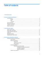
15 Plastics Kit ...16 Miscellaneous parts ...17 Sequential part number listing ...19 4 Removal and replacement procedures Preliminary replacement requirements 22 Tools required ...22 Service considerations ...22 Plastic parts ...22 Cables and connectors 22 Drive handling 23 Grounding guidelines - HP Mini 1100 | HP Mini 1000 NetBook - Maintenance and Service Guide - Page 6
8.9-inch, WSVGA display specifications 61 10.2-inch, WSVGA display specifications 62 Hard drive specifications ...63 Solid-state drive specifications ...64 System DMA specifications ...65 System interrupt specifications ...65 System I/O address specifications ...66 System memory map specifications - HP Mini 1100 | HP Mini 1000 NetBook - Maintenance and Service Guide - Page 7
82 Initiating a recovery in Windows 82 9 Connector pin assignments Audio-in (microphone) ...83 Audio-out (headphone) ...83 RJ-45 (network) ...84 Universal Serial Bus ...84 10 Power cord set requirements Requirements for all countries and regions 85 Requirements for specific countries and regions - HP Mini 1100 | HP Mini 1000 NetBook - Maintenance and Service Guide - Page 8
viii - HP Mini 1100 | HP Mini 1000 NetBook - Maintenance and Service Guide - Page 9
57-cm (1.8-inch) parallel ATA (PATA) hard drives Configuration: 60-GB, 4200-rpm Solid-state drive (SSD) based on multi-level cell (MLC) technology (select models only) Configurations: ● 8-GB ● 16-GB Models with solid-state drives also support the HP Mini Mobile Drive All models support external USB - HP Mini 1100 | HP Mini 1000 NetBook - Maintenance and Service Guide - Page 10
USB (no pass-through support on the expansion port). Keyboard/pointing device 92% keyboard TouchPad, with 2 TouchPad buttons and two-way scrolling (taps enabled as default) Power requirements 30-W UMA AC adapter (non-smart) with localized cable plug support AC adapter connector on cable 3-cell - HP Mini 1100 | HP Mini 1000 NetBook - Maintenance and Service Guide - Page 11
Category Serviceability Description Windows® XP Home SP3, ultra low-cost personal computer (ULCPC) edition Restore media: Backup software provided by operating system CD and recovery DVD End-user replaceable parts: AC adapter Battery (system) Memory module 3 - HP Mini 1100 | HP Mini 1000 NetBook - Maintenance and Service Guide - Page 12
power is on. Produce sound. Send and receive wireless signals to communicate with wireless local-area networks (WLANs). (4) Internal microphone (5) Webcam , you will need to install additional webcam software. * The antennae Support > User Guides. 4 Chapter 2 External component identification - HP Mini 1100 | HP Mini 1000 NetBook - Maintenance and Service Guide - Page 13
(3) (4) (5) Component esc key Function keys fn key Windows logo key Windows applications key Function Displays system information when pressed in combination in combination with a function key. Displays the Windows Start menu. Displays a shortcut menu for items beneath the pointer. Top components - HP Mini 1100 | HP Mini 1000 NetBook - Maintenance and Service Guide - Page 14
TouchPad Item Component Function (1) TouchPad on/off button (2) TouchPad on/off light (3) Left TouchPad button * (4) TouchPad * (5) TouchPad scroll zone (6) Right TouchPad button * Turns the TouchPad on and off. ● White: TouchPad is on. ● Amber: TouchPad is off. Functions like the - HP Mini 1100 | HP Mini 1000 NetBook - Maintenance and Service Guide - Page 15
and Maintenance > Power Options. Blinking: The hard drive or flash drive is being accessed. ● On: A battery is charging. ● Blinking: A battery that is the only available power source has reached a low battery level. When the battery reaches a critical battery level, the battery light begins blinking - HP Mini 1100 | HP Mini 1000 NetBook - Maintenance and Service Guide - Page 16
Vent SD Card Reader USB port HP Mobile Drive (only on models with solid-state drives) Security cable connector Supports the following optional digital card formats: ● MultiMediaCard (MMC) ● Secure Digital (SD) Memory Card Connects an optional USB device. Connects an optional HP Mini Mobile Drive - HP Mini 1100 | HP Mini 1000 NetBook - Maintenance and Service Guide - Page 17
battery power. USB port Vent Connects an optional USB device. Enables airflow to cool internal components. NOTE: The device fan starts up automatically to cool internal components and prevent overheating. It is normal for the internal fan to cycle on and off during routine operation. Expansion - HP Mini 1100 | HP Mini 1000 NetBook - Maintenance and Service Guide - Page 18
Bottom components Item (1) (2) (3) Component Battery bay Battery release latches (2) Memory module compartment (4) Vent Function Holds the battery. Release the battery from the battery bay. Contains the memory module slot. NOTE: The release latch for the memory module compartment cover (not - HP Mini 1100 | HP Mini 1000 NetBook - Maintenance and Service Guide - Page 19
number (p/n): This number provides specific information about the product's hardware components. The part number helps a service technician to determine what components and parts are needed. (4) Model description: This is the number used to locate documents, drivers, and support for the device - HP Mini 1100 | HP Mini 1000 NetBook - Maintenance and Service Guide - Page 20
Display assembly (includes webcam, 1 microphone, and 2 WLAN antenna transceivers/ cables) 8.9-inch WSVGA BrightView 10.2-inch WSVGA AntiGlare Refer to Display assembly components on page 15, for more display assembly component spare part information. 509698-001 507310-001 Keyboard For use in - HP Mini 1100 | HP Mini 1000 NetBook - Maintenance and Service Guide - Page 21
Hard drive (includes FPC cable and bracket): 60-GB, 4200-rpm 504601-001 Hard Drive Hardware Kit (includes bracket) 504607-001 Solid-state drive , spare part number 507708-001. Heat sink assembly (not illustrated) 515099-001 RTC battery 507707-001 System board (includes processor, USB board, - HP Mini 1100 | HP Mini 1000 NetBook - Maintenance and Service Guide - Page 22
MHz, DDR2) 1024-MB 504600-001 512-MB 504599-001 Memory module compartment cover (see Plastics Kit on page 16 for spare part number 507317-001 information) Battery 3-cell, 26-Wh Li-Pol for use in all countries and regions except Germany 504610-001 3-cell, 26-Wh Li-Pol for use only in Germany - HP Mini 1100 | HP Mini 1000 NetBook - Maintenance and Service Guide - Page 23
(includes left and right cables) 506338-001 506335-001 (3) Display bezel (for use with 8.9-inch panel only) (4) Webcam module 506333-001 504594-001 NOTE: The webcam module spare part kit does not include a webcam module cable. The webcam module cable is included in the Display Cable Kit, spare - HP Mini 1100 | HP Mini 1000 NetBook - Maintenance and Service Guide - Page 24
Item Description Display Screw Kit (for 8.9-inch panels only, not illustrated) Display panel foil shield (not illustrated) Plastics Kit Spare part number 509700-001 506334-001 Item Description Plastics Kit: (1) Memory module compartment cover (2) HP Mobile Drive cover (only on models with solid- - HP Mini 1100 | HP Mini 1000 NetBook - Maintenance and Service Guide - Page 25
screw ● Phillips PM2.5×9.0 screw System power printed circuit board (PCB) with USB and SIM VGA Cable Cable Kit ● Bluetooth module cable ● Internal display switch module ● Fan cable ● USB board cable Rubber Kit (contains 4 device feet and RJ-45 cover) Spare part number 496813-001 512852-001 490371 - HP Mini 1100 | HP Mini 1000 NetBook - Maintenance and Service Guide - Page 26
bracket (fits over power and USB ports) ● USB connector bracket ● 3G connector bracket ● Actuators for power switch and wireless switch ● Internal display switch bracket HP Mini Mobile Drive (supported on models with HP Mobile Drives) 2-GB 4-GB 8-GB Slip case Spare part number 507318-001 512329 - HP Mini 1100 | HP Mini 1000 NetBook - Maintenance and Service Guide - Page 27
504594-001 Webcam module NOTE: The webcam module spare part kit does not include a webcam module cable. The webcam module cable is included in the Display Cable Kit, spare part number 504597-001. 504595-001 Display enclosure (includes logo) 504596-001 Display Hinge Kit (for 8.9-inch panels only - HP Mini 1100 | HP Mini 1000 NetBook - Maintenance and Service Guide - Page 28
4200, 533-MHz, DDR2) 504600-001 1024-MB memory module (PC2-4200, 533-MHz, DDR2) 504601-001 60-GB, 4200-rpm hard drive (includes FPC cable and bracket) 504607-001 Hard Drive Hardware Kit (includes bracket) 504610-001 3-cell, 26-Wh Li-Pol battery for use in all countries and regions except Germany - HP Mini 1100 | HP Mini 1000 NetBook - Maintenance and Service Guide - Page 29
Bluetooth module cable is included in the Cable Kit, spare part number 507708-001. RTC battery Cable Kit 8.9-inch WSVGA BrightView display panel (includes LCD cable and foil shield) Display Rubber Kit (for 8.9-inch panels only) Display Screw Kit (for 8.9-inch panels only) VGA Cable Slip case HP Mini - HP Mini 1100 | HP Mini 1000 NetBook - Maintenance and Service Guide - Page 30
Using excessive force during disassembly and reassembly can damage plastic parts. Use care when handling the plastic parts. Apply pressure only at the points designated in the maintenance instructions. Cables and connectors CAUTION: When servicing the device, be sure that cables are placed in their - HP Mini 1100 | HP Mini 1000 NetBook - Maintenance and Service Guide - Page 31
on surfaces covered with at least one inch of shock-proof foam. Avoid dropping drives from any height onto any surface. After removing a hard drive, an optical drive, or a diskette drive, place it in a static-proof bag. Avoid exposing a hard drive to products that have magnetic fields, such as - HP Mini 1100 | HP Mini 1000 NetBook - Maintenance and Service Guide - Page 32
in many cases, ESD contains enough power to alter life expectancy. CAUTION: To prevent damage to the device when you are removing or installing ready to install them. Packing PCBs in foam-lined box Typical electrostatic voltage levels Relative humidity 10% 40% 35,000 V 15,000 V 12,000 V 5,000 - HP Mini 1100 | HP Mini 1000 NetBook - Maintenance and Service Guide - Page 33
Keep the work area free of nonconductive materials, such as ordinary plastic assembly aids and Styrofoam. ● Handle ESD-sensitive components, parts, and assemblies by the case or PCM laminate. Handle these items only at static-free workstations. ● Avoid contact with pins, leads, or circuitry. ● Turn - HP Mini 1100 | HP Mini 1000 NetBook - Maintenance and Service Guide - Page 34
straps with a minimum of one megohm ±10% resistance in the ground cords. To provide or boot straps) can be used at standing workstations and are compatible with most types of shoes or boots. aprons, and sleeve protectors ● with hard ties to the ground ● Field service kits replacement procedures - HP Mini 1100 | HP Mini 1000 NetBook - Maintenance and Service Guide - Page 35
user password If the device you are servicing has an unknown user password, follow battery (see Battery on page 30). 5. Remove the real-time clock (RTC) battery (see RTC battery on page 42). 6. Wait approximately 5 minutes. 7. Replace the RTC battery and reassemble the device. 8. Connect AC power - HP Mini 1100 | HP Mini 1000 NetBook - Maintenance and Service Guide - Page 36
number (p/n): This number provides specific information about the product's hardware components. The part number helps a service technician to determine what components and parts are needed. (4) Model description: This is the number used to locate documents, drivers, and support for the device - HP Mini 1100 | HP Mini 1000 NetBook - Maintenance and Service Guide - Page 37
Device feet The device feet are adhesive-backed rubber pads. The feet are included in the Rubber Kit, spare part number 504613-001. There are 4 rubber feet that are installed on the base enclosure in the locations illustrated below. Component replacement procedures 29 - HP Mini 1100 | HP Mini 1000 NetBook - Maintenance and Service Guide - Page 38
(2) and remove the battery (3) from the device. To install the battery, insert the rear edge of the battery into the battery bay and pivot the battery downward until it is seated. The battery release latch automatically locks the battery into place. 30 Chapter 4 Removal and replacement procedures - HP Mini 1100 | HP Mini 1000 NetBook - Maintenance and Service Guide - Page 39
to the device. 3. Disconnect the power from the device by first unplugging the power cord from the AC outlet and then unplugging the AC adapter from the device. 4. Remove the battery (see Battery on page 30). Remove the memory module: 1. Slide the right battery release latch to the inside or - HP Mini 1100 | HP Mini 1000 NetBook - Maintenance and Service Guide - Page 40
4. Remove the memory module (2) by pulling the module away from the slot at an angle. NOTE: Memory modules are designed with a notch (3) to prevent incorrect insertion into the memory module slot. Reverse this procedure to install a memory module. 32 Chapter 4 Removal and replacement procedures - HP Mini 1100 | HP Mini 1000 NetBook - Maintenance and Service Guide - Page 41
Spare part number 504611-AD1 504611-AB1 504611-281 504611-031 504611-001 Before removing the keyboard, power from the device by first unplugging the power cord from the AC outlet and then unplugging the AC adapter from the device. 4. Remove the battery (see Battery on page 30). Remove the keyboard - HP Mini 1100 | HP Mini 1000 NetBook - Maintenance and Service Guide - Page 42
on the display assembly. 5. Release the zero insertion force (ZIF) connector (1) to which the keyboard cable is attached, and then disconnect the cable (2) from the system board. 6. Remove the keyboard. Reverse this procedure to install the keyboard. 34 Chapter 4 Removal and replacement procedures - HP Mini 1100 | HP Mini 1000 NetBook - Maintenance and Service Guide - Page 43
outlet and then unplugging the AC adapter from the device. 4. Remove the battery (see Battery on page 30). 5. Remove the keyboard (see Keyboard on page 33). To remove the hard drive: 1. Release the ZIF connector (1) to which the USB board pass-through cable is attached. The cable lies across the top - HP Mini 1100 | HP Mini 1000 NetBook - Maintenance and Service Guide - Page 44
slide it out of the drive bay. Reverse this procedure to install the hard drive. To remove the solid-state drive: 1. Release the ZIF connector (1) to which the USB board pass-through cable (that lies across the top of the drive) is attached. 2. Disconnect the USB board pass-through cable (2), and - HP Mini 1100 | HP Mini 1000 NetBook - Maintenance and Service Guide - Page 45
Reverse this procedure to install the solid-state drive. Top cover Description Top cover (includes TouchPad) Spare part number 504612-001 Before 4. Remove the battery (see Battery on page 30). 5. Remove the keyboard (see Keyboard on page 33). 6. Remove the hard drive or solid-state drive (see Mass - HP Mini 1100 | HP Mini 1000 NetBook - Maintenance and Service Guide - Page 46
the device as far as possible. 6. Remove the black Phillips PM2.0×7.0 screw that secures the top cover to the base enclosure. 38 Chapter 4 Removal and replacement procedures - HP Mini 1100 | HP Mini 1000 NetBook - Maintenance and Service Guide - Page 47
which the TouchPad button board cable is connected, and then disconnect the cable (2) from the system board. 9. Remove the top cover. Reverse this procedure to install the top cover. Component replacement procedures 39 - HP Mini 1100 | HP Mini 1000 NetBook - Maintenance and Service Guide - Page 48
the battery (see Battery on page 30). 5. Remove the following components: a. Keyboard (see Keyboard on page 33) b. Hard drive or solid-state drive (see Mass storage devices on page 35) c. Top cover (see Top cover on page 37) Remove the WLAN module: 40 Chapter 4 Removal and replacement procedures - HP Mini 1100 | HP Mini 1000 NetBook - Maintenance and Service Guide - Page 49
If you replace the module and then receive a warning message, remove the module to restore device functionality, and then contact technical support through Help and Support. 1. (4) to prevent incorrect insertion. Reverse this procedure to install the WLAN module. Component replacement procedures 41 - HP Mini 1100 | HP Mini 1000 NetBook - Maintenance and Service Guide - Page 50
the AC outlet and then unplugging the AC adapter from the device. 4. Remove the battery (see Battery on page 30). 5. Remove the following components: a. Keyboard (see Keyboard on page 33) b. Hard drive or solid-state drive (see Mass storage devices on page 35) c. Top cover (see Top cover on page - HP Mini 1100 | HP Mini 1000 NetBook - Maintenance and Service Guide - Page 51
Remove the battery (see Battery on page 30). 5. Remove the following components: a. Keyboard (see Keyboard on page 33) b. Hard drive or solid-state drive (see Mass storage devices on page 35) c. Top cover (see Top cover on page 37) Remove the Bluetooth module: 1. Detach the Bluetooth module (1) from - HP Mini 1100 | HP Mini 1000 NetBook - Maintenance and Service Guide - Page 52
from the device. 4. Remove the battery (see Battery on page 30). 5. Remove the following components: a. Keyboard (see Keyboard on page 33) b. Hard drive or solid-state drive (see Mass storage devices on page 35) c. Top cover (see Top cover on page 37) When replacing the system board, be sure that - HP Mini 1100 | HP Mini 1000 NetBook - Maintenance and Service Guide - Page 53
(2) Microphone cable (3) Fan cable (4) Display panel cable NOTE: The USB board pass-through cable (5) was disconnected earlier (see Mass storage devices two silver Phillips PM2.0×3.0 screws (1) that secure the actuators for the power switch and wireless on/off switch to the system board, and then - HP Mini 1100 | HP Mini 1000 NetBook - Maintenance and Service Guide - Page 54
: The USB connector bracket is included in the Bracket Kit, spare part number 507318-001. 5. Grasp the system board at its midpoint (1) and lift the right side up (2). 6. Remove the system board (3). Reverse the procedure to install the system board. 46 Chapter 4 Removal and replacement procedures - HP Mini 1100 | HP Mini 1000 NetBook - Maintenance and Service Guide - Page 55
device. 4. Remove the battery (see Battery on page 30). 5. Remove the following components: a. Keyboard (see Keyboard on page 33) b. Hard drive or solid-state drive (see Mass storage devices assembly (2). Reverse this procedure to install the heat sink assembly. Component replacement procedures 47 - HP Mini 1100 | HP Mini 1000 NetBook - Maintenance and Service Guide - Page 56
device. 4. Remove the battery (see Battery on page 30). 5. Remove the following components: a. Keyboard (see Keyboard on page 33) b. Hard drive or solid-state drive (see Mass storage devices the fan (2). Reverse this procedure to install the fan. 48 Chapter 4 Removal and replacement procedures - HP Mini 1100 | HP Mini 1000 NetBook - Maintenance and Service Guide - Page 57
Remove the battery (see Battery on page 30). 5. Remove the following components: a. Keyboard (see Keyboard on page 33) b. Hard drive or solid-state drive (see Mass storage devices on page 35) c. Top cover (see Top cover on page 37) Remove the display assembly: CAUTION: Support the display assembly - HP Mini 1100 | HP Mini 1000 NetBook - Maintenance and Service Guide - Page 58
. b. Remove the two black Phillips PM2.0×8.0 screws (1) that secure the speaker assembly to the display enclosure. All display assembly subcomponent screws (for 8.9-inch panels only) are available in the Display Screw Kit, spare part number 509700-001. 50 Chapter 4 Removal and replacement procedures - HP Mini 1100 | HP Mini 1000 NetBook - Maintenance and Service Guide - Page 59
assembly is available using spare part number 506335-001. 4. If it is necessary to replace the display hinges, remove the two silver Phillips PM2.0×6.0 screws (1) that secure each hinge to the display enclosure, and then remove the hinges (2). The hinges (for 8.9-inch panels only) are available in - HP Mini 1100 | HP Mini 1000 NetBook - Maintenance and Service Guide - Page 60
from the display enclosure, and then remove the display bezel (4). The display bezel, spare part number 506333-001, is for use with 8.9-inch panel only. 6. If it is necessary to replace the webcam module, perform the following steps: a. Open the tab built into the display enclosure shielding - HP Mini 1100 | HP Mini 1000 NetBook - Maintenance and Service Guide - Page 61
the two black Phillips PM2.0×4.0 screws (1) that secure the webcam module to the display enclosure, and then remove the webcam module (2). The webcam module is available using spare part number 504594-001. 7. If it is necessary to replace the display panel, perform the following steps: a. Remove the - HP Mini 1100 | HP Mini 1000 NetBook - Maintenance and Service Guide - Page 62
c. Remove the display panel from the display enclosure (3). An 8.9-inch display panel (includes LCD cable and foil shield) is available as spare part number 508968-001. 8. If it is necessary to replace the display panel brackets, remove the two black Phillips PM2.0×4.0 screws (1) that secure each - HP Mini 1100 | HP Mini 1000 NetBook - Maintenance and Service Guide - Page 63
the display enclosure, and then remove the cables. The wireless antenna transceivers and cables (for 8.9-inch panels only) are available in the Display Cable Kit, spare part number 504597-001. Reverse this procedure to reassemble and install the display assembly. Component replacement procedures 55 - HP Mini 1100 | HP Mini 1000 NetBook - Maintenance and Service Guide - Page 64
and customization utility that can be used even when your Windows operating system is not working. The utility reports information about Utility, turn on or restart the device, and then press f10 while the "F10 = BIOS Setup Options" message is displayed in the lower-left corner of the screen. 2. Use - HP Mini 1100 | HP Mini 1000 NetBook - Maintenance and Service Guide - Page 65
not Windows based, it does not support the restore the Setup Utility default settings. If the Setup Utility is not already running, begin at step 1. If the Setup Utility is running, begin at step 2. 1. To open the Setup Utility, turn on or restart the device, and then press f10 while the "F10 = BIOS - HP Mini 1100 | HP Mini 1000 NetBook - Maintenance and Service Guide - Page 66
Changes, and then press enter. After either choice, the device restarts in Windows. Setup Utility menus The menu tables in this section provide an overview View specification information about the processor, memory size, and system BIOS. Security menu Select Administrator password Power-on - HP Mini 1100 | HP Mini 1000 NetBook - Maintenance and Service Guide - Page 67
Order-Set the boot order for: ● Set the boot order. ◦ Internal hard drive (select models only) ◦ USB Floppy ◦ USB CD/DVD ROM Drive ◦ USB Diskette on Key ◦ USB Hard drive ◦ USB Card Reader ◦ Network adapter Diagnostics menu Select Hard Disk Self Test (select models only) Memory Test To do this Run - HP Mini 1100 | HP Mini 1000 NetBook - Maintenance and Service Guide - Page 68
6 Specifications Device specifications Metric U.S. Dimensions Depth 16.67 cm 6.56 in Width 26.17 cm Height 2.52 cm Weight 10.2-in. LCD, equipped with a 3-cell battery, 60-GB hard drive, 1.11 kg 1-GB memory, WLAN module, and 2 wireless antennae 10.30 in 0.99 in 2.45 lbs 10.2-in. LCD, - HP Mini 1100 | HP Mini 1000 NetBook - Maintenance and Service Guide - Page 69
8.9-inch, WSVGA display specifications Dimensions Height Width Diagonal Number of colors Contrast ratio Brightness Pixel resolution Pitch Format Configuration Backlight Character display Total power consumption Viewing angle Metric U.S. 11.34 cm 19.51 22.61 cm 262,144 300:1 (typical) 200 nits ( - HP Mini 1100 | HP Mini 1000 NetBook - Maintenance and Service Guide - Page 70
10.2-inch, WSVGA display specifications Dimensions Height Width Diagonal Number of colors Contrast ratio Brightness Pixel resolution Pitch Format Configuration Backlight Character display Total power consumption Viewing angle Metric U.S. 12.53 cm 22.27 cm 25.55 cm 262,144 400:1 (typical) 200 - HP Mini 1100 | HP Mini 1000 NetBook - Maintenance and Service Guide - Page 71
Operating temperature *1 GB = 1 billion bytes when referring to hard drive storage capacity. Actual accessible capacity is less. Actual drive specifications may differ slightly. NOTE: Certain restrictions and exclusions apply. Contact technical support for details. Hard drive specifications 63 - HP Mini 1100 | HP Mini 1000 NetBook - Maintenance and Service Guide - Page 72
Solid-state drive specifications Performance Transfer modes supported Sustained read Sustained write Characteristics Interface MLC NAND flash capacity Electrical specifications DC supply voltage Standby current Active current Environmental specifications Operating temperature Storage temperature - HP Mini 1100 | HP Mini 1000 NetBook - Maintenance and Service Guide - Page 73
applicable Not applicable Not applicable Direct memory access controller System interrupt specifications Hardware IRQ IRQ0 IRQ1 IRQ8 IRQ9 ICH7 Family) PCI Express Root Port-27D0 Intel 82801G (ICH7 Family) USB Universal Host Controller-27CB Microsoft UAA Bus Driver for High Definition Audio Mobile - HP Mini 1100 | HP Mini 1000 NetBook - Maintenance and Service Guide - Page 74
DMA controller Motherboard resources DMA controller Motherboard resources DMA controller Motherboard resources Programmable interrupt controller Motherboard resources DMA controller Motherboard resources Numeric data processor Primary IDE channel ISAPNP Read Data Port 66 Chapter 6 Specifications - HP Mini 1100 | HP Mini 1000 NetBook - Maintenance and Service Guide - Page 75
82801G (ICH7 Family) SMBus Controller-27DA Motherboard resources Motherboard resources Motherboard resources Motherboard resources ISAPNP Read Data Port PCI bus Intel 82801G (ICH7 Family) USB Universal Host Controller-27C8 Intel 82801G (ICH7 Family) USB Universal Host Controller-27CA Intel 82801G - HP Mini 1100 | HP Mini 1000 NetBook - Maintenance and Service Guide - Page 76
System memory map specifications Memory address Port-27D0 Broadcom 802.11b/g WLAN Intel 82801G (ICH7 Family) PCI Express Root Port-27D2 Motherboard resources System board Motherboard resources Motherboard resources Motherboard resources System board Motherboard resources 68 Chapter 6 Specifications - HP Mini 1100 | HP Mini 1000 NetBook - Maintenance and Service Guide - Page 77
7 Screw listing This section provides specification and reference information for the screws and screw locks used in the device. All screws listed in this section are available in the Screw Kit, spare part number 504614-001, or in the Display Screw Kit, part number 509700-001. Phillips PM1.6×2.5 - HP Mini 1100 | HP Mini 1000 NetBook - Maintenance and Service Guide - Page 78
screw Color Silver Quantity 3 (hard-drive option) 5 (SSD option) Length 3.0 mm Thread 2.0 mm Head diameter 4.5 mm Where used: Two screws that secure the power and wireless switch actuators to the system board Where used: Two screws that secure the solid-state drive bracket to the device 70 - HP Mini 1100 | HP Mini 1000 NetBook - Maintenance and Service Guide - Page 79
Where used: One screw that secures the WLAN module to the system board Phillips PM2.0×4.0 screw Color Silver Quantity 19 Length 4.0 mm Thread 2.0 mm Head diameter 4.5 mm Where used: One screw that secures the keyboard to the device Phillips PM2.0×4.0 screw 71 - HP Mini 1100 | HP Mini 1000 NetBook - Maintenance and Service Guide - Page 80
Where used: Two screws that secure the USB connector bracket to the system board Where used: Two screws that secure the webcam module to the display enclosure Where used: Eight screws that secure the display panel to the display enclosure 72 Chapter 7 Screw listing - HP Mini 1100 | HP Mini 1000 NetBook - Maintenance and Service Guide - Page 81
Where used: Four screws that secure the left and right display panel brackets to the display panel Where used: Two screws that secure the fan to the base enclosure Phillips PM2.0×4.0 screw 73 - HP Mini 1100 | HP Mini 1000 NetBook - Maintenance and Service Guide - Page 82
Phillips PM2.0×6.0 screw Color Black Quantity 6 (hard-drive option) 4 (SSD option) Length 6.0 mm Thread 2.0 mm Head diameter 4.5 mm Where used: Two screws that secure the hard drive to the system board Where used: Four screws that secure the display hinges to the display assembly 74 Chapter 7 - HP Mini 1100 | HP Mini 1000 NetBook - Maintenance and Service Guide - Page 83
Phillips PM2.0×7.0 screw Color Silver Quantity 1 Length 7.0 mm Thread 2.0 mm Head diameter 4.5 mm Where used: One screw that secures the top cover to the device (top console) Phillips PM2.0×7.0 screw 75 - HP Mini 1100 | HP Mini 1000 NetBook - Maintenance and Service Guide - Page 84
Phillips PM2.0×8.0 screw Color Silver Quantity 2 Length 8.0 mm Thread 2.0 mm Head diameter 4.5 mm Where used: Two screws that secure the speaker assembly to the display enclosure 76 Chapter 7 Screw listing - HP Mini 1100 | HP Mini 1000 NetBook - Maintenance and Service Guide - Page 85
Phillips PM2.5×7.0 screw Color Silver Quantity 4 Length 7.0 mm Thread 2.5 mm Head diameter 5.0 mm Where used: Four screws that secure the display assembly to the device Phillips PM2.5×7.0 screw 77 - HP Mini 1100 | HP Mini 1000 NetBook - Maintenance and Service Guide - Page 86
Phillips PM2.5×9.0 screw Color Silver Quantity 4 Length 9.0 mm Thread 2.5 mm Head diameter 5.0 mm Where used: Four screws that secure the base enclosure to the device 78 Chapter 7 Screw listing - HP Mini 1100 | HP Mini 1000 NetBook - Maintenance and Service Guide - Page 87
8 Backup and recovery Backing up your information NOTE: You can recover only the files that you have previously backed up. HP recommends that you use the Windows backup utility to create a hard drive backup as soon as you set up your device. With the Windows backup utility, you can perform the - HP Mini 1100 | HP Mini 1000 NetBook - Maintenance and Service Guide - Page 88
an optional external hard drive or to a network drive. NOTE: This process will take several minutes, depending on the file size and the speed of the device. To back up individual files or folders: 1. Select Start > All Programs > Accessories > System Tools > Backup. The Backup or Restore Wizard page - HP Mini 1100 | HP Mini 1000 NetBook - Maintenance and Service Guide - Page 89
, and then click Next. 5. Follow the on-screen instructions. Creating recovery points When you back up system modifications since your last backup, you are creating system recovery points. This allows you to save a snapshot of your hard drive at a specific point in time. You can then recover back to - HP Mini 1100 | HP Mini 1000 NetBook - Maintenance and Service Guide - Page 90
a recovery in Windows, follow these steps: 1. If possible, back up all personal files. 2. Select Start > All Programs > Accessories > System Tools > Backup. The Backup or Restore Wizard page opens. 3. Click Restore files and settings, and then click Next. 4. Follow the on-screen instructions. 82 - HP Mini 1100 | HP Mini 1000 NetBook - Maintenance and Service Guide - Page 91
9 Connector pin assignments Audio-in (microphone) Pin Signal 1 Audio signal in 2 Audio signal in 3 Ground Audio-out (headphone) Pin Signal 1 Audio out, left channel 2 Audio out, right channel 3 Ground Audio-in (microphone) 83 - HP Mini 1100 | HP Mini 1000 NetBook - Maintenance and Service Guide - Page 92
RJ-45 (network) Pin Signal 1 Transmit + 2 Transmit - 3 Receive + 4 Unused 5 Unused 6 Receive - 7 Unused 8 Unused Universal Serial Bus Pin Signal 1 +5 VDC 2 Data - 3 Data + 4 Ground 84 Chapter 9 Connector pin assignments - HP Mini 1100 | HP Mini 1000 NetBook - Maintenance and Service Guide - Page 93
responsible for evaluation in the country or region where the power cord set will be used. ● The power cord sets must have a minimum current capacity of 10 amps and a nominal voltage rating of 125 or 250 V AC, as required by the power system of each country or region. ● The appliance coupler must - HP Mini 1100 | HP Mini 1000 NetBook - Maintenance and Service Guide - Page 94
specific countries and regions Country/region Accredited agency Applicable note number Australia EANSW 1 Austria OVE 1 Belgium CEBC 1 Canada must be Type HO5VV-F, 3-conductor, 1.0-mm² conductor size. Power cord set must be Type VCTF, 3-conductor, 0.75-mm² conductor size. Power cord set - HP Mini 1100 | HP Mini 1000 NetBook - Maintenance and Service Guide - Page 95
life, do not dispose of the battery in general household waste. Follow the local laws and regulations in your area for computer battery HP product contains mercury in the backlight in the display assembly that might require special handling at end-of-life disassembly instructions. Specific details, - HP Mini 1100 | HP Mini 1000 NetBook - Maintenance and Service Guide - Page 96
Perform the following steps to disassemble the display assembly: 1. Remove all screw covers (1) and screws (2) that secure the display bezel to the display assembly. 2. Lift up and out on the left and right inside edges (1) and the top and bottom inside edges (2) of the display bezel until the bezel - HP Mini 1100 | HP Mini 1000 NetBook - Maintenance and Service Guide - Page 97
4. Disconnect all display panel cables (1) from the display inverter and remove the inverter (2). 5. Remove all screws (1) that secure the display panel assembly to the display enclosure. 6. Remove the display panel assembly (2) from the display enclosure. 7. Turn the display panel assembly upside - HP Mini 1100 | HP Mini 1000 NetBook - Maintenance and Service Guide - Page 98
10. Remove the display panel frame (2) from the display panel. 11. Remove the screws (1) that secure the backlight cover to the display panel. 12. Lift the - HP Mini 1100 | HP Mini 1000 NetBook - Maintenance and Service Guide - Page 99
15. Remove the backlight cables (1) from the clip (2) in the display panel. 16. Turn the display panel upside down. WARNING! The backlight contains mercury. Exercise caution when removing and handling the backlight to avoid damaging this component and causing exposure to the mercury. 17. Remove the - HP Mini 1100 | HP Mini 1000 NetBook - Maintenance and Service Guide - Page 100
18. Remove the backlight from the backlight frame. 19. Disconnect the display panel cable (1) from the LCD panel. 20. Remove the screws (2) that secure the LCD panel to the display rear panel. 21. Release the LCD panel (3) from the display rear panel. 22. Release the tape (4) that secures the LCD - HP Mini 1100 | HP Mini 1000 NetBook - Maintenance and Service Guide - Page 101
number 15, 21 Display Screw Kit, spare part number 16, 21, 50 display specifications 61, 62 drive light 7 drives boot order 59 preventing damage 23 E electrostatic discharge 24 esc key 5 Ethernet, product description 2 expansion port, product description 2 external media cards, product description - HP Mini 1100 | HP Mini 1000 NetBook - Maintenance and Service Guide - Page 102
keyboard product description 2 removal 33 spare part number 12, 20, 33 L left-side components 9 lights battery 7 drive 7 power 7 power connector 9 TouchPad on/off 6 wireless 7 M mass storage device product description 1 removal 35 spare part number 13, 35 memory map specifications 68 memory module - HP Mini 1100 | HP Mini 1000 NetBook - Maintenance and Service Guide - Page 103
flash storage drive 1 graphics 1 hard drive 1 internal media cards 2 keyboard 2 mass storage device 1 memory module 1 modem 2 operating system 2 optical drive 1 panels 1 pointing device 2 ports 2 power requirements 2 processors 1 product name 1 security 2 serviceability 3 solid-state drive 1 webcam - HP Mini 1100 | HP Mini 1000 NetBook - Maintenance and Service Guide - Page 104
removal 55 spare part number 15, 55 WLAN module removal 40 spare part number 13, 19, 40 workstation guidelines 25 96 Index - HP Mini 1100 | HP Mini 1000 NetBook - Maintenance and Service Guide - Page 105
-
 1
1 -
 2
2 -
 3
3 -
 4
4 -
 5
5 -
 6
6 -
 7
7 -
8
-
9
-
10
-
11
-
12
-
13
-
14
-
15
-
16
-
17
-
18
-
19
-
20
-
21
-
22
-
23
-
24
-
25
-
26
-
27
-
28
-
29
-
30
-
31
-
32
-
33
-
34
-
35
-
36
-
37
-
38
-
39
-
40
-
41
-
42
-
43
-
44
-
45
-
46
-
47
-
48
-
49
-
50
-
51
-
52
-
53
-
54
-
55
-
56
-
57
-
58
-
59
-
60
-
61
-
62
-
63
-
64
-
65
-
66
-
67
-
68
-
69
-
70
-
71
-
72
-
73
-
74
-
75
-
76
-
77
-
78
-
79
-
80
-
81
-
82
-
83
-
84
-
85
-
86
-
87
-
88
-
89
-
90
-
91
-
92
-
93
-
94
-
95
-
96
-
97
-
98
-
99
-
100
-
101
-
102
-
103
-
104
-
105
 |
 |

HP Mini 1000 NetBook
Maintenance and Service Guide