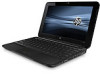
HP Mini 2102 HP Mini 2102, HP Mini 210, and Compaq Mini 210 - Maintenance and
HP Mini 2102 Manual
 |
View all HP Mini 2102 manuals
Add to My Manuals
Save this manual to your list of manuals |
HP Mini 2102 manual content summary:
- HP Mini 2102 | HP Mini 2102, HP Mini 210, and Compaq Mini 210 - Maintenance and - Page 1
HP Mini 2102, HP Mini 210, and Compaq Mini 210 Maintenance and Service Guide - HP Mini 2102 | HP Mini 2102, HP Mini 210, and Compaq Mini 210 - Maintenance and - Page 2
to change without notice. The only warranties for HP products and services are set forth in the express warranty statements accompanying such products and services. Nothing herein should be construed as constituting an additional warranty. HP shall not be liable for technical or editorial errors - HP Mini 2102 | HP Mini 2102, HP Mini 210, and Compaq Mini 210 - Maintenance and - Page 3
Safety warning notice WARNING! To reduce the possibility of heat-related injuries or of overheating the device, do not place the device directly on your lap or obstruct the device air vents. Use the device only on a hard, flat surface. Do not allow another hard surface, such as an adjoining optional - HP Mini 2102 | HP Mini 2102, HP Mini 210, and Compaq Mini 210 - Maintenance and - Page 4
iv Safety warning notice - HP Mini 2102 | HP Mini 2102, HP Mini 210, and Compaq Mini 210 - Maintenance and - Page 5
24 Sequential part number listing ...25 4 Removal and replacement procedures ...31 Preliminary replacement requirements 31 Tools required ...31 Service considerations ...31 Plastic parts ...31 Cables and connectors 32 Drive handling 32 Grounding guidelines ...33 Electrostatic discharge damage 33 - HP Mini 2102 | HP Mini 2102, HP Mini 210, and Compaq Mini 210 - Maintenance and - Page 6
Workstation guidelines 34 Equipment guidelines 35 Component replacement procedures 36 Service tag ...36 Computer feet ...37 Battery ...38 SIM ...39 Service cover ...40 Hard drive ...41 WWAN module ...43 WLAN module ...45 Memory module ...47 RTC battery ...48 Keyboard ...49 Top cover ...52 - HP Mini 2102 | HP Mini 2102, HP Mini 210, and Compaq Mini 210 - Maintenance and - Page 7
When to create restore points 75 Creating a system restore point 75 Restoring to a previous date and time 75 Backing up and recovering using HP Recovery Manager 76 Backing up your information 76 Creating a set of recovery discs 77 Performing a recovery ...78 Recovering using the recovery discs - HP Mini 2102 | HP Mini 2102, HP Mini 210, and Compaq Mini 210 - Maintenance and - Page 8
Index ...94 viii - HP Mini 2102 | HP Mini 2102, HP Mini 210, and Compaq Mini 210 - Maintenance and - Page 9
Panels Memory Description HP Mini 2102 and Compaq Mini HP Mini 210 210 HP Mini 2102 √ HP Mini 210 √ Compaq Mini 210 √ Intel® Atom 667-MHz, DDR2 √ √ Supports the following configurations: √ √ ● 2048-MB total system memory (2048 × 1) NOTE: Supported on computers with Windows® - HP Mini 2102 | HP Mini 2102, HP Mini 210, and Compaq Mini 210 - Maintenance and - Page 10
Diskette drive Audio/Visual Modem Ethernet Wireless Description HP Mini 2102 and Compaq Mini HP Mini 210 210 Supports the following 9.5-mm (0.37-in) × 6.35-cm (2.50- √ √ inch), parallel SATA, 7200-rpm hard drives: ● 320-GB NOTE: Supported only on computers with Windows 7. ● 250-GB NOTE - HP Mini 2102 | HP Mini 2102, HP Mini 210, and Compaq Mini 210 - Maintenance and - Page 11
Category Description HP Mini 2102 and Compaq Mini HP Mini 210 210 External media Digital Media Slot (consumer models) or Media Card √ √ cards Reader (commercial models) with push-push technology supporting: ● Memory Stick (MS) ● MS/Pro ● MultiMediaCard (MMC) ● Secure Digital High - HP Mini 2102 | HP Mini 2102, HP Mini 210, and Compaq Mini 210 - Maintenance and - Page 12
Category Serviceability Description Support for HP QuickWeb FreeDOS End-user replaceable parts: AC adapter Battery (system) Hard drive Memory module WLAN module WWAN module HP Mini 2102 and Compaq Mini HP Mini 210 210 √ √ √ √ √ √ √ √ √ √ √ √ √ √ √ 4 Chapter 1 Product description - HP Mini 2102 | HP Mini 2102, HP Mini 210, and Compaq Mini 210 - Maintenance and - Page 13
2 External component identification Identifying the hardware Components included with the computer may vary by region and model. The illustrations in this chapter identify the standard features on most computer models. To see a list of hardware installed in the computer, follow these steps: 1. - HP Mini 2102 | HP Mini 2102, HP Mini 210, and Compaq Mini 210 - Maintenance and - Page 14
Top components TouchPad Item Component Description (1) TouchPad on/off button (2) TouchPad Turns the TouchPad on and off. Quickly double-tap the button to turn the TouchPad on and off. Moves the pointer and selects or activates items on the screen. (3) Left TouchPad button* Functions like - HP Mini 2102 | HP Mini 2102, HP Mini 210, and Compaq Mini 210 - Maintenance and - Page 15
Lights Item Component (1) TouchPad light (2) Caps lock light (3) Mute light (4) Wireless light Description ● On: The TouchPad is disabled. ● Off: The TouchPad is enabled. On: Caps lock is on. On: Speaker sound is off. ● White: An integrated wireless device, such as a wireless local area - HP Mini 2102 | HP Mini 2102, HP Mini 210, and Compaq Mini 210 - Maintenance and - Page 16
Keys Item Component (1) Action keys (2) fn key (3) Windows logo key (4) Windows applications key Front components Component Speakers (2) Description Execute frequently used system functions. Executes frequently used system functions when pressed in combination with a function key or the - HP Mini 2102 | HP Mini 2102, HP Mini 210, and Compaq Mini 210 - Maintenance and - Page 17
Right-side components item Component (1) Digital Media Slot (2) Power light (3) Power switch (4) Vent (5) USB ports (2) Description Supports the following optional digital card formats: ● Memory Stick (MS) ● MS/Pro ● MultiMediaCard (MMC) ● Secure Digital High Capacity (SDHC) Memory Card - HP Mini 2102 | HP Mini 2102, HP Mini 210, and Compaq Mini 210 - Maintenance and - Page 18
is normal for the internal fan to cycle on and off during routine operation. ● Blinking: The hard drive is being accessed. ● Amber (select models only): HP ProtectSmart Hard Drive Protection has temporarily parked the hard drive. 10 Chapter 2 External component identification - HP Mini 2102 | HP Mini 2102, HP Mini 210, and Compaq Mini 210 - Maintenance and - Page 19
item Component Description (6) USB port Connects an optional USB device. (7) Audio-out (headphone) jack/Audio-in (microphone) jack Produces sound when connected to optional powered stereo speakers, headphones, earbuds, a headset, or television audio. Also connects an optional headset - HP Mini 2102 | HP Mini 2102, HP Mini 210, and Compaq Mini 210 - Maintenance and - Page 20
Bottom components item Component (1) Battery release latches (2) (2) Battery bay Description Release the battery from the battery bay. Holds the battery. 12 Chapter 2 External component identification - HP Mini 2102 | HP Mini 2102, HP Mini 210, and Compaq Mini 210 - Maintenance and - Page 21
to the section of the Regulatory, Safety and Environmental Notices that applies to your country or region. To access these notices, select Start > Help and Support > User Guides. Wireless antennas 13 - HP Mini 2102 | HP Mini 2102, HP Mini 210, and Compaq Mini 210 - Maintenance and - Page 22
the service tag. (1) Product name: This is the product name affixed to the front of the device. (2) Serial number (s/n): This is an alphanumeric identifier that is unique to each product. (3) Model description: This is the alphanumeric identifier used to locate documents, drivers, and support for - HP Mini 2102 | HP Mini 2102, HP Mini 210, and Compaq Mini 210 - Maintenance and - Page 23
panel cable, 2 WLAN transceivers and cables, 2 WWAN transceivers and cables, and webcam/microphone module and cable): For use only with HP 2102 and Mini 210 computer models: ● HD, AntiGlare, flush glass display assembly in black ● HD, AntiGlare, flush glass display assembly in blue ● HD, AntiGlare - HP Mini 2102 | HP Mini 2102, HP Mini 210, and Compaq Mini 210 - Maintenance and - Page 24
589643-001 589641-001 589649-001 589651-001 10.1-in, WSVGA, AntiGlare, standard display assembly in black for use only with Compaq 589640-001 Mini 210 computer models Keyboard (includes cable) With painted surface: ● For use in Belgium ● For use in Brazil ● For use in the Czech Republic ● For use - HP Mini 2102 | HP Mini 2102, HP Mini 210, and Compaq Mini 210 - Maintenance and - Page 25
Item (3) Description ● For use in Thailand ● For use in Turkey ● For use in the United Kingdom ● For use in the United States With textured surface: ● For use in Belgium ● For use in Brazil ● For use in the Czech Republic ● For use in Denmark, Finland, and Norway ● For use in France ● For use in - HP Mini 2102 | HP Mini 2102, HP Mini 210, and Compaq Mini 210 - Maintenance and - Page 26
Item Description Spare part number In red 589687-001 In silver 589686-001 (4) TouchPad (includes cable and bracket (4b)): For use only with black top cover 589677-001 For use only with blue top cover 589685-001 For use only with red top cover 589684-001 For use only with silver top - HP Mini 2102 | HP Mini 2102, HP Mini 210, and Compaq Mini 210 - Maintenance and - Page 27
Item Description Spare part number ● For use in Afghanistan, Albania, Algeria, Andorra, Angola, Antigua and Barbuda, 518436-002 Argentina, Armenia, Aruba, Australia, Austria, Azerbaijan, the Bahamas, Bahrain, Bangladesh, Barbados, Belarus, Belgium, Belize, Benin, Bermuda, Bhutan, Bolivia, - HP Mini 2102 | HP Mini 2102, HP Mini 210, and Compaq Mini 210 - Maintenance and - Page 28
802.11b/g WiFi and 2070 Bluetooth 2.1+EDR Combo Adapter (13) HP un2400 Mobile Broadband WWAN module (14) Hard drive (includes cable and 2 rubber feet) 3-cell, 28-WHr (includes 2 release latches) (16) Service cover Spare part number 575920-001 531993-001 590819-001 589670-001 589667-001 589673-001 - HP Mini 2102 | HP Mini 2102, HP Mini 210, and Compaq Mini 210 - Maintenance and - Page 29
(includes WLAN antenna transceivers and cables and WWAN antenna transceivers and cables): For use only with HP Mini 2102 and 210 computer models 589656-001 For use only with Compaq Mini 210 computer models 589655-001 Display panel: 10.1-in, HD, AntiGlare display panel 589653-001 10.1-in - HP Mini 2102 | HP Mini 2102, HP Mini 210, and Compaq Mini 210 - Maintenance and - Page 30
and cables and WWAN antenna transceivers and cables): For use only with HP computer models in black For use only with HP computer models in blue For use only with HP computer models in red For use only with HP computer models in silver For use only with Compaq computer models Display Screw - HP Mini 2102 | HP Mini 2102, HP Mini 210, and Compaq Mini 210 - Maintenance and - Page 31
Mass storage devices NOTE: Each hard drive spare part kit includes a cable adapter, bracket, and 4 isolators. Item (1) (3) Description Hard drive: 320-GB, 7200-RPM 250-GB, 7200-RPM 160-GB, 7200-RPM Hard Drive Hardware Kit (not illustrated) External optical drive: Blu-ray ROM DVD±R/RW SuperMulti - HP Mini 2102 | HP Mini 2102, HP Mini 210, and Compaq Mini 210 - Maintenance and - Page 32
Miscellaneous parts Description 40-W UMA AC adapter Power cord: For use in Argentina For use in Austalia For use in Brazil For use in Denmark For use in Europe For use in Israel For use in Italy For use in Japan For use in Norway For use in the People's Republic of China For use in Singapore and the - HP Mini 2102 | HP Mini 2102, HP Mini 210, and Compaq Mini 210 - Maintenance and - Page 33
Sequential part number listing Spare part number 449729-001 490371-001 490371-011 490371-021 490371-031 490371-061 490371-081 490371-111 490371-201 490371-291 490371-AA1 490371-AB1 490371-AD1 490371-AR1 490371-BB1 490371-D01 490371-D61 504593-003 504593-004 Description RTC battery Power cord for - HP Mini 2102 | HP Mini 2102, HP Mini 210, and Compaq Mini 210 - Maintenance and - Page 34
cables, and webcam/microphone module and cable) 10.1-in HD, AntiGlare, flush glass display assembly in red for use only with HP Mini 2102 and 210 computer models (includes display panel cable, 2 WLAN transceivers and cables, 2 WWAN transceivers and cables, and webcam/microphone module and cable) 26 - HP Mini 2102 | HP Mini 2102, HP Mini 210, and Compaq Mini 210 - Maintenance and - Page 35
cables, and webcam/microphone module and cable) 10.1-in HD, AntiGlare, flush glass display assembly in blue for use only with HP Mini 2102 and 210 computer models (includes display panel cable, 2 WLAN transceivers and cables, 2 WWAN transceivers and cables, and webcam/microphone module and cable) 10 - HP Mini 2102 | HP Mini 2102, HP Mini 210, and Compaq Mini 210 - Maintenance and - Page 36
TouchPad for use only with black top cover (includes cable and bracket ) Base enclosure (includes 4 rubber feet and power connector bracket) Service cover Rubber Kit (includes 4 rubber feet and RJ-45 cover) Fan/heat sink assembly (includes replacement thermal material) Power connector cable TouchPad - HP Mini 2102 | HP Mini 2102, HP Mini 210, and Compaq Mini 210 - Maintenance and - Page 37
Spare part number 590526-AB1 590526-AD1 590526-B31 590526-BA1 590526-BB1 590526-BG1 590526-DH1 590526-DJ1 590527-001 590527-031 590527-041 590527-051 590527-061 590527-071 590527-121 590527-131 590527-141 590527-161 590527-171 590527-201 590527-211 590527-221 590527-251 590527-281 590527-291 590527- - HP Mini 2102 | HP Mini 2102, HP Mini 210, and Compaq Mini 210 - Maintenance and - Page 38
Spare part number 590543-001 590544-001 590819-001 596153-001 606695-001 Description 3-cell, 28-WHr battery (includes 2 release latches) 6-cell, 62-WHr battery (includes 2 release latches and 2 rubber feet) 320-GB, 7200-rpm hard drive (includes cable adapter, 4 rubber isolators, and hard drive - HP Mini 2102 | HP Mini 2102, HP Mini 210, and Compaq Mini 210 - Maintenance and - Page 39
● Flat-bladed screwdriver ● Magnetic screwdriver ● Phillips P0 and P1 screwdrivers Service considerations The following sections include some of the considerations that you must keep in pressure only at the points designated in the maintenance instructions. Preliminary replacement requirements 31 - HP Mini 2102 | HP Mini 2102, HP Mini 210, and Compaq Mini 210 - Maintenance and - Page 40
Cables and connectors CAUTION: When servicing the device, be sure that cables are placed in their proper locations during the reassembly process. Improper cable placement can damage the device. Cables must - HP Mini 2102 | HP Mini 2102, HP Mini 210, and Compaq Mini 210 - Maintenance and - Page 41
Grounding guidelines Electrostatic discharge damage Electronic components are sensitive to electrostatic discharge (ESD). Circuitry design and structure determine the degree of sensitivity. Networks built into many integrated circuits provide some protection, but in many cases, ESD contains enough - HP Mini 2102 | HP Mini 2102, HP Mini 210, and Compaq Mini 210 - Maintenance and - Page 42
material. ● Use a wrist strap connected to a properly grounded work surface and use properly grounded tools and equipment. ● Use conductive field service tools, such as cutters, screwdrivers, and vacuums. ● When fixtures must directly contact dissipative surfaces, use fixtures made only of static - HP Mini 2102 | HP Mini 2102, HP Mini 210, and Compaq Mini 210 - Maintenance and - Page 43
with ground cords of one megohm resistance ● Static-dissipative tables or floor mats with hard ties to the ground ● Field service kits ● Static awareness labels ● Material-handling packages ● Nonconductive plastic bags, tubes, or boxes ● Metal tote boxes ● Electrostatic voltage levels and - HP Mini 2102 | HP Mini 2102, HP Mini 210, and Compaq Mini 210 - Maintenance and - Page 44
the service tag. (1) Product name: This is the product name affixed to the front of the device. (2) Serial number (s/n): This is an alphanumeric identifier that is unique to each product. (3) Model description: This is the alphanumeric identifier used to locate documents, drivers, and support for - HP Mini 2102 | HP Mini 2102, HP Mini 210, and Compaq Mini 210 - Maintenance and - Page 45
Computer feet The computer feet are adhesive-backed rubber pads. The feet are included in the Rubber Feet Kit, spare part number 589680-001. There are 4 rubber feet that attach to the base enclosure in the locations shown in the following illustration. Component replacement procedures 37 - HP Mini 2102 | HP Mini 2102, HP Mini 210, and Compaq Mini 210 - Maintenance and - Page 46
Battery Description 6-cell, 62-WHr (includes 2 release latches and 2 rubber feet) 3-cell, 28-WHr (includes 2 release latches) Spare part number 590544-001 590543-001 Before disassembling the computer, follow these steps: 1. Shut down the computer. If you are unsure whether the computer is off or - HP Mini 2102 | HP Mini 2102, HP Mini 210, and Compaq Mini 210 - Maintenance and - Page 47
SIM Before removing the SIM, follow these steps: 1. Shut down the computer. If you are unsure whether the computer is off or in Hibernation, turn the computer on, and then shut it down through the operating system. 2. Disconnect all external devices connected to the computer. 3. Disconnect the - HP Mini 2102 | HP Mini 2102, HP Mini 210, and Compaq Mini 210 - Maintenance and - Page 48
AC adapter from the computer. 4. Remove the battery (see Battery on page 38). Remove the service cover: 1. Simultaneously press in on the right release button (1) and release the right side of the service cover (2). 2. Simultaneously press in on the left release button (3) and release the left side - HP Mini 2102 | HP Mini 2102, HP Mini 210, and Compaq Mini 210 - Maintenance and - Page 49
power cord from the AC outlet and then unplugging the AC adapter from the computer. 4. Remove the battery (see Battery on page 38). 5. Remove the service cover (see Battery on page 38). Remove the hard drive: 1. Disconnect the hard drive cable (1) from the system board. 2. Use the Mylar tab (2) on - HP Mini 2102 | HP Mini 2102, HP Mini 210, and Compaq Mini 210 - Maintenance and - Page 50
3. Remove the hard drive (4) by sliding it up and to the right at an angle. 4. If it is necessary to replace the hard drive bracket, follow these steps: a. Disconnect the cable adapter (1) from the hard drive. b. Remove the four Phillips PM3.0×3.0 screws (2) that secure the hard drive bracket to the - HP Mini 2102 | HP Mini 2102, HP Mini 210, and Compaq Mini 210 - Maintenance and - Page 51
HP remove the module to restore device functionality, and then contact technical support. Before removing the WWAN module, follow these steps: 1. Shut Remove the battery (see Battery on page 38). 5. Remove the service cover (see Service cover on page 40). Remove the WWAN module: 1. Disconnect the - HP Mini 2102 | HP Mini 2102, HP Mini 210, and Compaq Mini 210 - Maintenance and - Page 52
3. Remove the WWAN module (4) by pulling the module away from the slot at an angle. NOTE: WWAN modules are designed with a notch (5) to prevent incorrect insertion of the WWAN module into the WWAN module slot. Reverse this procedure to install the WWAN module. 44 Chapter 4 Removal and replacement - HP Mini 2102 | HP Mini 2102, HP Mini 210, and Compaq Mini 210 - Maintenance and - Page 53
WLAN module Description Spare part number Atheros 9285G 802.11b/g/n 1×1 WiFi Adapter module: For use in Canada, the Cayman Islands, Guam, Puerto Rico, the U.S. Virgin Islands, and the United States 518436-001 For use in Afghanistan, Albania, Algeria, Andorra, Angola, Antigua and Barbuda, - HP Mini 2102 | HP Mini 2102, HP Mini 210, and Compaq Mini 210 - Maintenance and - Page 54
to restore computer functionality, and then contact technical support through Help and Support. Before removing the WLAN module, follow these steps Remove the battery (see Battery on page 38). 5. Remove the service cover (see Service cover on page 40). Remove the WLAN module: 1. Disconnect the - HP Mini 2102 | HP Mini 2102, HP Mini 210, and Compaq Mini 210 - Maintenance and - Page 55
from the AC outlet and then unplugging the AC adapter from the computer. 4. Remove the battery (see Battery on page 38). 5. Remove the service cover (see Service cover on page 40). Remove the memory module: 1. Pull away the retention clips (1) on each side of the memory module to release the memory - HP Mini 2102 | HP Mini 2102, HP Mini 210, and Compaq Mini 210 - Maintenance and - Page 56
cord from the AC outlet and then unplugging the AC adapter from the computer. 4. Remove the battery (see Battery on page 38). 5. Remove the service cover (see Service cover on page 40). Remove the RTC battery: ▲ Remove the RTC battery from the socket on the system board. Reverse this procedure to - HP Mini 2102 | HP Mini 2102, HP Mini 210, and Compaq Mini 210 - Maintenance and - Page 57
Keyboard NOTE: The keyboard spare part kit includes a keyboard cable. For use in: With painted finish: Belgium Brazil The Czech Republic Denmark, Finland, and Norway France French Canada Germany Greece Hungary Israel Italy Japan Latin America With textured finish: Belgium Brazil The Czech Republic - HP Mini 2102 | HP Mini 2102, HP Mini 210, and Compaq Mini 210 - Maintenance and - Page 58
the AC outlet and then unplugging the AC adapter from the computer. 4. Remove the battery (see Battery on page 38). 5. Remove the service cover (see Service cover on page 40). Remove the keyboard: 1. Remove the three Phillips PM2.0×6.0 screws that secure the keyboard to the computer. 2. Turn the - HP Mini 2102 | HP Mini 2102, HP Mini 210, and Compaq Mini 210 - Maintenance and - Page 59
6. Release the zero insertion force (ZIF) connector (3) to which the keyboard cable is attached, and then disconnect the keyboard cable (4) from the system board. 7. Remove the keyboard. Reverse this procedure to install the keyboard. Component replacement procedures 51 - HP Mini 2102 | HP Mini 2102, HP Mini 210, and Compaq Mini 210 - Maintenance and - Page 60
cord from the AC outlet and then unplugging the AC adapter from the computer. 4. Remove the battery (see Battery on page 38). 5. Remove the service cover (see Service cover on page 40). 6. Remove the keyboard (see Keyboard on page 49). Remove the top cover. 1. Turn the computer upside down, with the - HP Mini 2102 | HP Mini 2102, HP Mini 210, and Compaq Mini 210 - Maintenance and - Page 61
6. Release the ZIF connector (2) to which the TouchPad cable is connected, and then disconnect the TouchPad cable (3) from the system board. 7. Remove the five Phillips PM2.0×6.0 screws that secure the top cover to the base enclosure. 8. Release the top cover (1) by lifting the rear edge until it - HP Mini 2102 | HP Mini 2102, HP Mini 210, and Compaq Mini 210 - Maintenance and - Page 62
9. Remove the top cover (2) by lifting it straight up. Reverse this procedure to install the top cover. 54 Chapter 4 Removal and replacement procedures - HP Mini 2102 | HP Mini 2102, HP Mini 210, and Compaq Mini 210 - Maintenance and - Page 63
and then unplugging the AC Adapter from the computer. 4. Remove the battery (see Battery on page 38). 5. Remove the following components: a. Service cover (see Service cover on page 40). b. Keyboard (see Keyboard on page 49). c. Top cover (see Top cover on page 52). Remove the speakers: 1. Turn - HP Mini 2102 | HP Mini 2102, HP Mini 210, and Compaq Mini 210 - Maintenance and - Page 64
outlet and then unplugging the AC adapter from the computer. 4. Remove the battery (see Battery on page 38). 5. Remove the following components: a. Service cover (see Service cover on page 40). b. Keyboard (see Keyboard on page 49). c. Top cover (see Top cover on page 52). d. Speakers (see Speakers - HP Mini 2102 | HP Mini 2102, HP Mini 210, and Compaq Mini 210 - Maintenance and - Page 65
6. Remove the TouchPad (5) by sliding it forward. Reverse this procedure to install the TouchPad. Component replacement procedures 57 - HP Mini 2102 | HP Mini 2102, HP Mini 210, and Compaq Mini 210 - Maintenance and - Page 66
, and webcam/microphone module and cable): For use only with HP Mini 2102 and 210 computer models: ● HD, AntiGlare, flush glass display assembly in Remove the battery (see Battery on page 38). 5. Remove the service cover (see Service cover on page 40). 6. Disconnect the WWAN antenna cables from the - HP Mini 2102 | HP Mini 2102, HP Mini 210, and Compaq Mini 210 - Maintenance and - Page 67
system board. 7. Release the wireless antenna cables (2) from the clip built into the base enclosure. CAUTION: Support the display assembly when removing the following screws. Failure to support the display assembly can result in damage to the display assembly and other device components. Component - HP Mini 2102 | HP Mini 2102, HP Mini 210, and Compaq Mini 210 - Maintenance and - Page 68
8. Remove the two Phillips PM2.0×4.0 screws (1) that secure the display assembly to the base enclosure. 9. Remove the display assembly (2). Reverse this procedure to reassemble and install the display assembly. 60 Chapter 4 Removal and replacement procedures - HP Mini 2102 | HP Mini 2102, HP Mini 210, and Compaq Mini 210 - Maintenance and - Page 69
from the AC outlet and then unplugging the AC adapter from the computer. 4. Remove the battery (see Battery on page 38). 5. Remove the service cover (see Service cover on page 40). 6. Disconnect the hard drive cable from the system board (see Hard drive on page 41). 7. Disconnect the WWAN antenna - HP Mini 2102 | HP Mini 2102, HP Mini 210, and Compaq Mini 210 - Maintenance and - Page 70
2. Disconnect the power connector cable (2) from the system board. 3. Remove the Phillips PM2.0×4.0 screw (1) that secures the system board to the base enclosure. 4. Lift the right side of the system board (2) until it rests at an angle. 5. Remove the system board (3) by sliding it up and away from - HP Mini 2102 | HP Mini 2102, HP Mini 210, and Compaq Mini 210 - Maintenance and - Page 71
from the AC outlet and then unplugging the AC adapter from the computer. 4. Remove the battery (see Battery on page 38). 5. Remove the service cover (see Service cover on page 40). 6. Disconnect the hard drive cable from the system board (see Hard drive on page 41). 7. Disconnect the WWAN antenna - HP Mini 2102 | HP Mini 2102, HP Mini 210, and Compaq Mini 210 - Maintenance and - Page 72
board each time the fan/heat sink assembly is removed: Thermal paste is used on the processor (1) and the fan/heat sink assembly section (2) that services it. Reverse this procedure to install the fan/heat sink assembly. 64 Chapter 4 Removal and replacement procedures - HP Mini 2102 | HP Mini 2102, HP Mini 210, and Compaq Mini 210 - Maintenance and - Page 73
from the AC outlet and then unplugging the AC adapter from the computer. 4. Remove the battery (see Battery on page 38). 5. Remove the service cover (see Service cover on page 40). 6. Disconnect the hard drive cable from the system board (see Hard drive on page 41). 7. Disconnect the WWAN antenna - HP Mini 2102 | HP Mini 2102, HP Mini 210, and Compaq Mini 210 - Maintenance and - Page 74
3. Remove the power connector cable (3). Reverse this procedure to install the power connector cable. 66 Chapter 4 Removal and replacement procedures - HP Mini 2102 | HP Mini 2102, HP Mini 210, and Compaq Mini 210 - Maintenance and - Page 75
5 Setup Utility Starting Setup Utility Setup Utility is a ROM-based information and customization utility that can be used even when your Windows operating system is not working. The utility reports information about the computer and provides settings for startup, security, and other preferences. To - HP Mini 2102 | HP Mini 2102, HP Mini 210, and Compaq Mini 210 - Maintenance and - Page 76
Navigating and selecting in Setup Utility Because Setup Utility is not Windows based, it does not support the TouchPad. Navigation and selection are by keystroke. ● To choose a menu or a menu item, use the arrow keys. ● To choose an item in a list or - HP Mini 2102 | HP Mini 2102, HP Mini 210, and Compaq Mini 210 - Maintenance and - Page 77
section provide an overview of the Setup Utility options NOTE: Some of the Setup Utility menu items listed in this chapter may not be supported by your computer. Select System information To do this ● View and change the system time and date. ● View identification information about the computer - HP Mini 2102 | HP Mini 2102, HP Mini 210, and Compaq Mini 210 - Maintenance and - Page 78
System Configuration Menu Select Language Support Processor C4 State Boot Options Diagnostics Menu f12 functions of Setup Utility in intervals of 5 seconds each (0, 5, 10, 15, 20). ● HP QuickWeb―Enable/disable the QuickWeb Boot menu in Setup Utility. ● Internal Network Adapter boot―Enable/disable - HP Mini 2102 | HP Mini 2102, HP Mini 210, and Compaq Mini 210 - Maintenance and - Page 79
, you may have one of the following backup and recovery solutions: ● Roxio BackOnTrack ● HP Recovery Manager NOTE: For detailed information, perform a search for these topics in Help and Support. Backing up and recovering using Roxio BackOnTrack Successful recovery after a system failure depends on - HP Mini 2102 | HP Mini 2102, HP Mini 210, and Compaq Mini 210 - Maintenance and - Page 80
screen. 8. Follow the on-screen instructions. Performing a recovery In case of system state if a software-related problem occurs. The Instant Restore saving the current computer state manually. For more information about Disaster Recovery is available from the HP Web site in a compressed file - HP Mini 2102 | HP Mini 2102, HP Mini 210, and Compaq Mini 210 - Maintenance and - Page 81
a USB port on your computer. 2. Open your Web browser, go to http://www.hp.com/support, and select your country or region. 3. Enter the SoftPaq number SP42226 in the Search box, press enter, and then follow the onscreen instructions. 4. Click Download only to save the file to your computer. 5. When - HP Mini 2102 | HP Mini 2102, HP Mini 210, and Compaq Mini 210 - Maintenance and - Page 82
All Programs, click Maintenance, and then click Backup and Restore. 2. Follow the on-screen instructions to set up and create a backup. NOTE: Windows includes the User Account Control feature to settings. Refer to Help and Support for more information. 74 Chapter 6 Backup and recovery (Windows only) - HP Mini 2102 | HP Mini 2102, HP Mini 210, and Compaq Mini 210 - Maintenance and - Page 83
tab. 4. Under Protection Settings, select the disk for which you want to create a restore point. 5. Click Create. 6. Follow the on-screen instructions. Restoring to a previous date and time To revert to a restore point (created at a previous date and time) when the computer was functioning - HP Mini 2102 | HP Mini 2102, HP Mini 210, and Compaq Mini 210 - Maintenance and - Page 84
tools provided by the operating system and by HP Recovery Manager software are designed to help you Creating a set of recovery discs ● Creating system restore points ● Recovering a program or driver ● Performing a full system recovery Backing up your information As you add new software and data - HP Mini 2102 | HP Mini 2102, HP Mini 210, and Compaq Mini 210 - Maintenance and - Page 85
, number each disc before inserting it into an optical drive. Creating a set of recovery discs HP recommends that you create recovery discs to be sure that you can restore your system to its Recovery Manager, and then click Recovery Disc Creation. 2. Follow the on-screen instructions. Windows 7 77 - HP Mini 2102 | HP Mini 2102, HP Mini 210, and Compaq Mini 210 - Maintenance and - Page 86
Start, and then click Help and Support. NOTE: Recovery Manager recovers only a hub or docking station. 3. Follow the on-screen instructions. Recovering using the partition on the hard drive (select NOTE: This method of recovery is also an HP Recovery Manager solution. NOTE: Computers with an SSD - HP Mini 2102 | HP Mini 2102, HP Mini 210, and Compaq Mini 210 - Maintenance and - Page 87
, click System Recovery. 3. Follow the on-screen instructions. Windows XP To protect your information, back up access the Disaster Recovery utility. Therefore, HP recommends that you download the Disaster Recovery utility for these topics in Help and Support. Backing up your information Successful - HP Mini 2102 | HP Mini 2102, HP Mini 210, and Compaq Mini 210 - Maintenance and - Page 88
the computer screen. 8. Follow the on-screen instructions. Performing a recovery In case of system failure a working state if a software-related problem occurs. The Instant Restore utility automatically state by saving the current computer state manually. For more information about computer system - HP Mini 2102 | HP Mini 2102, HP Mini 210, and Compaq Mini 210 - Maintenance and - Page 89
a USB port on your computer. 2. Open your Web browser, go to http://www.hp.com/support, and select your country or region. 3. Enter the SoftPaq number SP42226 in the Search box, press enter, and then follow the onscreen instructions. 4. Click Download only to save the file to your computer. 5. When - HP Mini 2102 | HP Mini 2102, HP Mini 210, and Compaq Mini 210 - Maintenance and - Page 90
displayed on the screen, press f6 repeatedly until the Windows status bar is displayed. 3. When the Roxio BackOnTrack screen is displayed, follow the on-screen instructions. 82 Chapter 6 Backup and recovery (Windows only) - HP Mini 2102 | HP Mini 2102, HP Mini 210, and Compaq Mini 210 - Maintenance and - Page 91
7 Connector pin assignments Audio-in (microphone) Pin 1 2 3 Audio-out (headphone) Signal Audio signal in Audio signal in Ground Pin Signal 1 Audio out, left channel 2 Audio out, right channel 3 Ground Audio-in (microphone) 83 - HP Mini 2102 | HP Mini 2102, HP Mini 210, and Compaq Mini 210 - Maintenance and - Page 92
External monitor Pin 1 2 3 4 5 6 7 8 9 10 11 12 13 14 15 Signal Red analog Green analog Blue analog Not connected Ground Ground analog Ground analog Ground analog +5 VDC Ground Monitor detect DDC 2B data Horizontal sync Vertical sync DDC 2B clock 84 Chapter 7 Connector pin assignments - HP Mini 2102 | HP Mini 2102, HP Mini 210, and Compaq Mini 210 - Maintenance and - Page 93
RJ-45 (network) Pin 1 2 3 4 5 6 7 8 Universal Serial Bus Signal Transmit + Transmit Receive + Unused Unused Receive Unused Unused Pin Signal 1 +5 VDC 2 Data 3 Data + 4 Ground RJ-45 (network) 85 - HP Mini 2102 | HP Mini 2102, HP Mini 210, and Compaq Mini 210 - Maintenance and - Page 94
8 Power cord set requirements The wide-range input feature of the computer permits it to operate from any line voltage from 100 to 120 volts AC, or from 220 to 240 volts AC The 3-conductor power cord set included with the computer meets the requirements for use in the country or region where the - HP Mini 2102 | HP Mini 2102, HP Mini 210, and Compaq Mini 210 - Maintenance and - Page 95
Requirements for specific countries and regions Country/region Accredited agency Applicable note number Australia EANSW 1 Austria OVE 1 Belgium CEBC 1 Canada CSA 2 Denmark DEMKO 1 Finland FIMKO 1 France UTE 1 Germany VDE 1 Italy IMQ 1 Japan METI 3 The Netherlands - HP Mini 2102 | HP Mini 2102, HP Mini 210, and Compaq Mini 210 - Maintenance and - Page 96
remove these components, handle them carefully. NOTE: Materials Disposal. This HP product contains mercury in the backlight in the display assembly that site at http://www.eiai.org. This section provides disassembly instructions for the display assembly. The display assembly must be disassembled - HP Mini 2102 | HP Mini 2102, HP Mini 210, and Compaq Mini 210 - Maintenance and - Page 97
Perform the following steps: 1. Remove all screw covers (1) and screws (2) that secure the display bezel to the display assembly. 2. Lift up and out on the left and right inside edges (1) and the top and bottom inside edges (2) of the display bezel until the bezel disengages from the display - HP Mini 2102 | HP Mini 2102, HP Mini 210, and Compaq Mini 210 - Maintenance and - Page 98
4. Disconnect all display panel cables (1) from the display inverter and remove the inverter 2. 5. Remove all screws (1) that secure the display panel assembly to the display enclosure. 6. Remove the display panel assembly (2) from the display enclosure. 7. Turn the display panel assembly upside - HP Mini 2102 | HP Mini 2102, HP Mini 210, and Compaq Mini 210 - Maintenance and - Page 99
10. Remove the display panel frame (2) from the display panel. 11. Remove the screws (1) that secure the backlight cover to the display panel. 12. Lift the top edge of the backlight cover (2) and swing it outward. 13. Remove the backlight cover. 14. Turn the display panel right-side up. Display 91 - HP Mini 2102 | HP Mini 2102, HP Mini 210, and Compaq Mini 210 - Maintenance and - Page 100
15. Remove the backlight cables (1) from the clip (2) in the display panel. 16. Turn the display panel upside down. 17. Remove the backlight frame from the display panel. WARNING! The backlight contains mercury. Exercise caution when removing and handling the backlight to avoid damaging this - HP Mini 2102 | HP Mini 2102, HP Mini 210, and Compaq Mini 210 - Maintenance and - Page 101
19. Disconnect the display cable (1) from the LCD panel. 20. Remove the screws (2) that secure the LCD panel to the display rear panel. 21. Release the LCD panel (3) from the display rear panel. 22. Release the tape (4) that secures the LCD panel to the display rear panel. 23. Remove the LCD panel. - HP Mini 2102 | HP Mini 2102, HP Mini 210, and Compaq Mini 210 - Maintenance and - Page 102
12 Blu-ray ROM DVD±R/RW SuperMulti Drive, spare part number 23, 26 boot options 70 buttons TouchPad 6 TouchPad on/off 6 C cables, service considerations 32 caps lock light 7 changing the language of Setup Utility 67 chipset, product description 1 components bottom 12 display 11 front 8 left-side - HP Mini 2102 | HP Mini 2102, HP Mini 210, and Compaq Mini 210 - Maintenance and - Page 103
29, 49 keys action 8 fn 8 Windows applications 8 Windows logo 8 L language support 70 lights battery 10 caps lock 7 drive 10 mute 7 power 9 TouchPad 7 webcam 3 power requirements 3 processors 1 product name 1 security 3 serviceability 4 video 2 wireless 2 product name 1 R removal/replacement - HP Mini 2102 | HP Mini 2102, HP Mini 210, and Compaq Mini 210 - Maintenance and - Page 104
Utility 69 security, product description 3 selecting in Setup Utility 68 serial number 14 service considerations 31 service cover removal 40 spare part number 20, 28, 40 service tag 14, 36 serviceability, product description 4 Setup Utility changing the language 67 Diagnostics Menu 70 exiting 69 - HP Mini 2102 | HP Mini 2102, HP Mini 210, and Compaq Mini 210 - Maintenance and - Page 105
-
 1
1 -
 2
2 -
 3
3 -
 4
4 -
 5
5 -
 6
6 -
 7
7 -
8
-
9
-
10
-
11
-
12
-
13
-
14
-
15
-
16
-
17
-
18
-
19
-
20
-
21
-
22
-
23
-
24
-
25
-
26
-
27
-
28
-
29
-
30
-
31
-
32
-
33
-
34
-
35
-
36
-
37
-
38
-
39
-
40
-
41
-
42
-
43
-
44
-
45
-
46
-
47
-
48
-
49
-
50
-
51
-
52
-
53
-
54
-
55
-
56
-
57
-
58
-
59
-
60
-
61
-
62
-
63
-
64
-
65
-
66
-
67
-
68
-
69
-
70
-
71
-
72
-
73
-
74
-
75
-
76
-
77
-
78
-
79
-
80
-
81
-
82
-
83
-
84
-
85
-
86
-
87
-
88
-
89
-
90
-
91
-
92
-
93
-
94
-
95
-
96
-
97
-
98
-
99
-
100
-
101
-
102
-
103
-
104
-
105
 |
 |

HP Mini 2102, HP Mini 210, and
Compaq Mini 210
Maintenance and Service Guide