HP Model 744 HP Model 744 Owner's Guide
HP Model 744 - VME Workstation Manual
 |
View all HP Model 744 manuals
Add to My Manuals
Save this manual to your list of manuals |
HP Model 744 manual content summary:
- HP Model 744 | HP Model 744 Owner's Guide - Page 1
Model 744 Owner's Guide This guide contains installation instructions. HP Part No. A4511-90602 Edition E0897 Printed in U.S.A. - HP Model 744 | HP Model 744 Owner's Guide - Page 2
© Hewlett-Packard Co. 1997 Printing History First Printing: September 1996 Latest Printing: August 1997 UNIX is a registered trademark in the United States and other countries, licensed exclusively through X/Open Company Limited. NOTICE The information contained in this document is subject to change - HP Model 744 | HP Model 744 Owner's Guide - Page 3
ESD) Precautions Preface-4 Release Document(s) Preface-4 Related Manuals Preface-5 Revision History Preface-6 Documentation Conventions Preface-7 Questions, Suggestions, or Problems Preface-8 Declaration of Conformity Preface-9 1 Model 744 Board Computer Overview Product Description 1-3 Installation - HP Model 744 | HP Model 744 Owner's Guide - Page 4
11 Operating System Overview 1-13 Manuals for System Information 1-14 HP-UX 1-14 HP VUE 1-14 For information on using and configuring the HP VUE interface with HP-UX, see HP VUE User's Guide. For information on installing HP VUE, refer to HP VUE Installation Guide. 1-14 HP CDE 1-14 Online Sources of - HP Model 744 | HP Model 744 Owner's Guide - Page 5
Tools Required 3-8 Preliminary Requirements 3-8 Installing a Single-Slot Model 744 into an HP Card Cage 3-8 Installing a Dual-Slot Model 744 3-9 Non-HP Installation 3-10 HP Installation (Other Than Primary CPU) 3-11 Model 744 Removal 3-12 Tools Required 3-12 Preliminary Requirements 3-12 Removing - HP Model 744 | HP Model 744 Owner's Guide - Page 6
Connection 4-9 Video Connection 4-12 Keyboard and Mouse Connections 4-13 Network Connection 4-14 Printer Connections 4-16 Preparing for HP-UX Installation 4-16 Configuring HP-UX for a Printer 4-16 Printer Interface 4-16 Printer Cables 4-17 Installation Procedure 4-17 Testing the Printer Installation - HP Model 744 | HP Model 744 Owner's Guide - Page 7
Interpreting the LEDs 6-3 Managing a Boot Failure 6-5 Printer Problems 6-6 A The Boot Console Interface Boot Console User Interface Features A-2 Main Menu A-3 Configuration Menu A-4 Information Menu A-5 Service Menu A-5 VME Menu A-6 Accessing the Boot Console Interface A-7 Booting Your Workstation - HP Model 744 | HP Model 744 Owner's Guide - Page 8
Contents Setting the Auto Boot and Auto Search and Auto Start Flags A-26 Displaying and Setting the Security Mode A-28 Displaying and Setting the Fastboot Mode A-29 Displaying the LAN Station Address A-30 Displaying System Information A-31 Displaying PIM Information A-32 Displaying and Setting VME - HP Model 744 | HP Model 744 Owner's Guide - Page 9
Springs and Labels 2-23 Installing the Board Computer with PMC into VME Card Cage 2-24 Model 744 Memory Slots 3-5 Board Computer Captive Screws 3-9 Board Computer Captive Screws 3-13 Model 744 Front Panel Connectors 4-3 Connecting a Monitor to HCRX, GSC, or On-Board Video Connector 4-6 Connecting - HP Model 744 | HP Model 744 Owner's Guide - Page 10
3-5 Model 744/165L Memory Card Current Usage Worksheet 3-5 Model 744 Current Requirements Worksheet 3-6 Monitor Conversion Cables Required 4-5 Audio Specifications 4-10 Audio Connector Pinouts 4-11 Video Connector Pins and Signals 4-12 PS/2 Connector Pinouts 4-13 AUI LAN Connector Pinouts 4-15 HP - HP Model 744 | HP Model 744 Owner's Guide - Page 11
Preface This owner's guide describes how to install and use the HP Model 744 Board Computer. Preface-1 - HP Model 744 | HP Model 744 Owner's Guide - Page 12
guide is intended for HP 9000 Model 744 Board Computer users. Safety and Regulatory Statements Safety For safety information see the owner's guide that came with the system in which you are installing your Model 744 and used in accordance with the instructions, may cause harmful interference to radio - HP Model 744 | HP Model 744 Owner's Guide - Page 13
Hewlett-Packard's system certification tests were conducted with HP-supported peripheral devices and HP shielded cables, such as those you receive with your computer. Changes or modifications not expressly approved by Hewlett-Packard could void the user's authority - HP Model 744 | HP Model 744 Owner's Guide - Page 14
the Release Document(s) you received with your system or system software for additional information that we may not have been able to include in this guide at the time of its publication. Preface-4 - HP Model 744 | HP Model 744 Owner's Guide - Page 15
If you are using HP-UX version 10.20, refer to the following manuals for more information: • Model 748 Owner's Guide (A4511-90604) • Using Your HP Workstation (A2615-90003) • Installing and Updating HP-UX (B2355-90050) • Graphics Administration Guide (B2355-90109) • Configuring HP-UX for Peripherals - HP Model 744 | HP Model 744 Owner's Guide - Page 16
Revision History The revision history for each edition of the manual is listed below: HP Part No. A4500-90607 A4511-90602 Edition E0996 E0897 Revision History First printing Updated to include Model 744/165L, PMC, and memory enhancements Preface-6 - HP Model 744 | HP Model 744 Owner's Guide - Page 17
Conventions Unless otherwise noted in the text, this guide uses the following symbolic conventions. user-supplied button which is drawn on your workstation's graphic display. (In this manual we refer to the Enter key. On your keyboard the key may be labeled either Enter or Return.) Preface-7 - HP Model 744 | HP Model 744 Owner's Guide - Page 18
Questions, Suggestions, or Problems If you have any questions, suggestions, or problems with our hardware, software, or documentation, please contact your HP Response Center. Preface-8 - HP Model 744 | HP Model 744 Owner's Guide - Page 19
Declaration of Conformity Preface-9 - HP Model 744 | HP Model 744 Owner's Guide - Page 20
Preface-10 - HP Model 744 | HP Model 744 Owner's Guide - Page 21
Preface-11 - HP Model 744 | HP Model 744 Owner's Guide - Page 22
Preface-12 - HP Model 744 | HP Model 744 Owner's Guide - Page 23
1 Model 744 Board Computer Overview 1-1 - HP Model 744 | HP Model 744 Owner's Guide - Page 24
Computer Overview This chapter introduces the Model 744 Board Computer. Its purpose is to familiarize you with the board computer and its installation procedure. The instructions in this chapter assume you are using either the HP-UX or HP-RT operating system. The major sections within this chapter - HP Model 744 | HP Model 744 Owner's Guide - Page 25
and expander boards) • CPU PA-RISC PA7300-LC, processor performance Model 744/132L - 132 MHz Primary internal cache - 128 KB: 64 KB instruction, 64KB data Model 744/165L - 165 MHz Primary internal cache - 128 KB: 64 KB instruction, 64KB data Secondary cache - 512 KB • Clocks Battery-backed real - HP Model 744 | HP Model 744 Owner's Guide - Page 26
may also be installed from an external DDS or CD-ROM drive. If the Model 744 is a client on a LAN, HP-UX can be booted over the LAN. HP-RT 2.21 (or later). • User interface CDE or HP VUE graphical user interface (HP-UX only). • Compatibility Source and binary code compatible with Series 700 product - HP Model 744 | HP Model 744 Owner's Guide - Page 27
the on-board graphics chip set of a Model 744 Board Computer. However, the HP-RT operating system supports only one graphics display, and HP-UX 10.x supports up to three graphics displays. • Main Memory Single VME slot 744: 32, 64, or 128 MB RAM Single VME slot 744 with HP-RT: 16 to 128 MB RAM Dual - HP Model 744 | HP Model 744 Owner's Guide - Page 28
Model 744 Board Computer Overview Product Description • Dual Slot Upgrades PMC bridge board (with two PMC sites, cannot be used w/HCRX, and supported only on HP-UX) GSC Expansion kit (with two GSC sites) HCRX8 graphics board (with one additional GSC site) HCRX24 graphics board (with one additional - HP Model 744 | HP Model 744 Owner's Guide - Page 29
products. Installation instructions for most products used directly with your Model 744 Board Computer are explained in this manual. Chapter exists between them. This situation has been tested by HP and full functionality is maintained. The Model 744 Board Computer's P2 connector has a local bus on - HP Model 744 | HP Model 744 Owner's Guide - Page 30
describe the products supported by HP. Accessory Cards The Model 744 supports the following accessory cards: • HP A4219A expansion kit • Memory; one or more of the following RAM cards is supported on either the HP-UX or HP-RT operating system: HP A4501A 16 MB RAM card (HP-RT only) HP A4502A 32 MB - HP Model 744 | HP Model 744 Owner's Guide - Page 31
the micro-miniature connectors to standard size interfaces. The Model 744 supports the following cables: • Conversion cables: HP A4300A HP parallel; high-density 25-pin to standard 25-pin F HP A4301A RS-232; high-density 9-pin to standard 9-pin M HP A4302A audio; high-density 9-pin to stereo line-in - HP Model 744 | HP Model 744 Owner's Guide - Page 32
Model 744 Board Computer Overview Supported Products Keyboard and Mouse The Model 744 supports the following: • HP A2840A keyboard with mini-DIN connector • HP A2839A mouse with mini-DIN connector 1-10 - HP Model 744 | HP Model 744 Owner's Guide - Page 33
Computer Overview Environmental Requirements Environmental Requirements Table 1-1 shows the environmental requirements for the Model 744. Table 1-1 Environmental Requirements Temperature Operating: 0˚ to 55˚C; 10˚c/min rate of change maximum Non-operating: -40˚ to 70˚C Humidity Operating - HP Model 744 | HP Model 744 Owner's Guide - Page 34
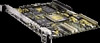
Tj = 85 Tj = 100 Tc= 75 Tj = 95 (744/132L = 102 (744/165L) Tj = 85 Tj = Maximum junction temperature in degrees centigrade Tc = Maximum case temperature in degrees centigrade Figure 1-1 Model 744 Board Computer (Top View) NOTE: The Model 744 should only be operated in an environment that is - HP Model 744 | HP Model 744 Owner's Guide - Page 35
can be used with either of two operating systems, HP-UX or HP-RT. This manual provides basic information you will need for booting and running HP-UX. It also provides some overview information for HP-RT. The Model 744 uses the standard HP-UX 10.20 or later operating system, a highly versatile system - HP Model 744 | HP Model 744 Owner's Guide - Page 36
Window System, Using HP-UX, CDE User's Guide, or HP VUE User's Guide. The following manuals are also useful: • If you have not yet installed your HP-UX OS, see Installing HP-UX. • For troubleshooting HP-UX, see Chapter 6 of this manual, and the manual Solving HP-UX Problems. • For VME configuration - HP Model 744 | HP Model 744 Owner's Guide - Page 37
Model 744 Board Computer Overview Online Sources of Information Online Sources of Information HP-UX is designed so that you can Panel, or by entering man command on a command line, where command is the name of the HP-UX command or routine you want to get information on. If you're not sure of the - HP Model 744 | HP Model 744 Owner's Guide - Page 38
Model 744 Board Computer Overview Online Sources of Information • Newconfig: The directory /usr/newconfig/etc contains information and new versions of HP-UX product configuration files, as well as shell scripts which may have been customized on your system. The contents of this directory will vary - HP Model 744 | HP Model 744 Owner's Guide - Page 39
Model 744 Board Computer Overview Installing HP-UX and HP-RT Installing HP-UX and HP-RT For procedures to install and configure HP-UX, refer to HP-UX System Administration Tasks. For information on clusters, refer to Managing Clusters of HP-UX Computers, and HP VUE User's Guide. For procedures to - HP Model 744 | HP Model 744 Owner's Guide - Page 40
Board Computer Overview Audio Audio HP-UX includes audio software comprising an audio editor, Audio Application Program Interface (AAPI), and some sample programs. Audio output is available through the audio port on the front panel of the Model 744. For highest quality audio, an external headphone - HP Model 744 | HP Model 744 Owner's Guide - Page 41
2 Installing Accessories 2-1 - HP Model 744 | HP Model 744 Owner's Guide - Page 42
Installing Accessories This chapter describes the accessories you can install on the Model 744 Board Computer and tells you how to install them. The instructions in this chapter assume you are using either the HP-UX or HP-RT operating system. The major sections within this chapter are: • Tools - HP Model 744 | HP Model 744 Owner's Guide - Page 43
steps before installing or removing accessories: 1 Exit application programs. 2 Shut down the operating system and power off the VMEVME chassis. (See Chapter 5 for detailed instructions.) 3 Remove all cables connected to the board computer. 4 Set up a static-free place on which to work. 2-3 - HP Model 744 | HP Model 744 Owner's Guide - Page 44
Installing Accessories Safety Precautions Safety Precautions It is essential to practice safety precautions when working with any electrical or electronic products. Following these safety precautions can help protect both you and the equipment from injury and possible permanent damage. Whether the - HP Model 744 | HP Model 744 Owner's Guide - Page 45
steps before you install a RAM card into the Model 744: 1 If the Model 744 is already installed in your system chassis, you must re- move it. See Chapter 3 of this manual for instructions on removing and replacing the Model 744. 2 Place the Model 744 on a static-free mat on a clean, level surface - HP Model 744 | HP Model 744 Owner's Guide - Page 46
Installing Accessories Memory 5 Properly align the connectors by slightly rotating the RAM card until you can feel the connectors fit together. 6 Gently and evenly push on the top of the connectors with both of your thumbs until the RAM cards are about 1/3 seated. 7 After the connectors are 1/3 - HP Model 744 | HP Model 744 Owner's Guide - Page 47
Installing Accessories Memory RAM Card Removal When removing RAM cards from the Model 744 CPU or the RAM card stack, remove the cards one at a time. Carefully lift the card by the edge near the connectors. Do not try to pry the card up with a tool. Figure 2-1 Installing RAM Cards 2-7 - HP Model 744 | HP Model 744 Owner's Guide - Page 48
Board Computer is already installed in your system chassis, you must remove it. See Chapter 3 of this manual for instructions on removing and replacing the Model 744. 2 Place the Model 744 on a static-free mat on a clean, level surface. GSC Expansion Kit Installation Follow these steps to install - HP Model 744 | HP Model 744 Owner's Guide - Page 49
Installing Accessories GSC Expansion Kit GCS Card GSC Expansion Kit Figure 2-2 M2.5X12 Screws M2.5X6 Screws Installing the GSC Expansion Kit (Exploded View with GSC Card) 2-9 - HP Model 744 | HP Model 744 Owner's Guide - Page 50
Installing Accessories GSC Expansion Kit Figure 2-3 Adding the Front Panel Screws 2-10 - HP Model 744 | HP Model 744 Owner's Guide - Page 51
Computer is already installed in your system chassis, you must remove it. See Chapter 3 of this manual for instructions on removing and replacing the Model 744. 3 Place the Model 744 Board Computer on a static-free mat on a clean, level surface. GSC Mezzanine Card Installation Follow these steps - HP Model 744 | HP Model 744 Owner's Guide - Page 52
) Installing an HCRX Graphics Board An HCRX8 or HCRX24 graphics board occupies the same position as the expansion kit adapter. These boards fasten to the 744 in almost the same way as the expansion adapter, with four M2.5X12 screws and two M2.5X6 screws. On an HCRX board, there are - HP Model 744 | HP Model 744 Owner's Guide - Page 53
is already installed in your system chassis, you must re- move it. See Chapter 3 of this book for instructions on removing and replacing the Model 744. 2 Place the Model 744 on a static-free mat on a clean, level surface. There is one GSC connector on the left side of an HCRX board. A GSC card is - HP Model 744 | HP Model 744 Owner's Guide - Page 54
Installing Accessories GSC Mezzanine Cards Front Panel Screws M2.5X6 Screws M2.5X12 Screws Figure 2-5 Installing an HCRX Graphics Board 2-14 - HP Model 744 | HP Model 744 Owner's Guide - Page 55
3 of this book for instructions on removing and replacing the Model 744 Board Computer. 2 Place the Model 744 on a static-free mat on a clean, level surface. PMC Bridge Adapter and Expansion Adapter Installation 1 Refer to your third party PMC card installation manual, and set any con- figuration - HP Model 744 | HP Model 744 Owner's Guide - Page 56
Installing Accessories PMC Bridge Adapter and Expansion Adapter Bezel blank O-Ring Gasket PMC Card Site 2 Site 1 Bridge Adapter Figure 2-6 Installing a PMC Card onto the PMC Bridge Adapter 2-16 - HP Model 744 | HP Model 744 Owner's Guide - Page 57
Installing Accessories PMC Bridge Adapter and Expansion Adapter 4 Remove the copper EMI gasketing from the front panel of the board computer. 5 Install the PMC bridge adapter onto the board computer as shown in Figure 2-7. There are four screws that secure the front bezel, and four screws that - HP Model 744 | HP Model 744 Owner's Guide - Page 58
Accessories PMC Bridge Adapter and Expansion Adapter 6 If you are installing the PMC expansion adapter, refer to your third party PMC card installation manual, and set any configuration switches or jumpers that may be required for your application. 7 On the PMC expansion adapter, remove the bezel - HP Model 744 | HP Model 744 Owner's Guide - Page 59
Installing Accessories PMC Bridge Adapter and Expansion Adapter 9 Remove the four screws from bridge adapter VME connectors, as shown in Figure 2-9. 10 Using a small screwdriver or razor, remove the copper EMI gasket on the front bezel of the bridge adapter, as shown in Figure 2-9. Bridge Adapter - HP Model 744 | HP Model 744 Owner's Guide - Page 60
Installing Accessories PMC Bridge Adapter and Expansion Adapter 11 Screw the four threaded standoffs into the bridge adapter's VME connectors. 12 Making sure that the connector and bezels are properly aligned, install the PMC expansion adapter onto the bridge adapter, as shown in Figure 2-10. Ensure - HP Model 744 | HP Model 744 Owner's Guide - Page 61
a three board assembly, we recommend that you install the ejector handle sleeves included in your kit. The procedure is as follows: a Remove the logo and model labels from the ejector handles on your board computer, as shown in Figure 2-11 - HP Model 744 | HP Model 744 Owner's Guide - Page 62
Installing Accessories PMC Bridge Adapter and Expansion Adapter b Slide the sleeves over each set of handles, as shown in Figure 2-12. Sleeves Figure 2-12 Installing Ejector Handle Sleeves 2-22 - HP Model 744 | HP Model 744 Owner's Guide - Page 63
on the PMC expansion board, and with the springs compressed, slide the labels from the Model 744 Board Computer into the sleeves, as shown in Figure 2-13. To properly identify the board computer model and manufacturer, we strongly advise that the original labels from the board computer be placed - HP Model 744 | HP Model 744 Owner's Guide - Page 64
card cage, as required to open the slots the new assembly will occupy. 15 Insert the Model 744 with the attached PMC adapter(s) into card cage slots until the they seat properly and the 2-14 Captive Screws Ejector Handles Figure 2-14 2-24 Installing the Board Computer with PMC into VME Card Cage - HP Model 744 | HP Model 744 Owner's Guide - Page 65
for the VME card cage and boot the operating system. 18 Log in as root and use the SAM utility to configure the HP-UX kernel for PCI support. (PMC cards require PCI drivers in the kernel.) 19 When SAM has started, choose the Kernel Configuration -> menu. 20 From the Kernel Configuration - HP Model 744 | HP Model 744 Owner's Guide - Page 66
PCMCIA PCMCIA For information on installing a PCMCIA adapter and a flash disk card, see HP Z5117A PCMCIA Adapter Installation and User's Guide (Z511790001). The PCMCIA adapter may not be installed on a Model 744 board computer that has built-in graphics. PCMCIA is supported under HP-RT only. 2-26 - HP Model 744 | HP Model 744 Owner's Guide - Page 67
3 Typical Installation in a VME Card Cage 3-1 - HP Model 744 | HP Model 744 Owner's Guide - Page 68
Typical Installation in a VME Card Cage This chapter describes the Model 744 Board Computer and tells you how to install it. The instructions in this chapter assume you are using either the HP-UX or HP-RT operating system. The major sections within this chapter are: • Configuring the VME Card Cage • - HP Model 744 | HP Model 744 Owner's Guide - Page 69
Cage This section provides step-by-step instructions for configuring the VME card cage. Use Table 3-1 to determine the configuration for the VME card cage. Determining the VME Card Cage Configuration If your Model 744 Board Computer... Then... has an HP A4262A Expansion Kit attached, and will be - HP Model 744 | HP Model 744 Owner's Guide - Page 70
Card Cage Configuring the VME Card Cage 2 To determine the maximum current usage of the Model 744 memory cards, either use Figure 3-1 and Table 3-2 (for Model 744/132L) or Table 3-3 (for Model 744/165L). You must work with the worst case power draw to correctly determine power usage. Determine worst - HP Model 744 | HP Model 744 Owner's Guide - Page 71
worst case active bank(s) for your calculation. 2 Slot positions and amount of 32MB cards determine the number of active banks. Table 3-3 Model 744/165L Memory Card Current Usage Worksheet Memory Card Size First Active Bank1 Second Active Bank Third Active Bank Inactive Banks Totals (+12V - HP Model 744 | HP Model 744 Owner's Guide - Page 72
from Table 3-4. 4 Shut down your VME application and power off the VME card cage. If your VME card cage backplane is autoconfiguring, see "Model 744 Installation" later in this chapter. If not, refer to your VME card cage documentation for configuring the VME backplane. Go to Step 5. 5 Ensure the - HP Model 744 | HP Model 744 Owner's Guide - Page 73
Mouse Keyboard and Mouse This section provides step-by-step instructions for connecting a keyboard and mouse to your Model 744. 1 Unpack your new keyboard and place it near your Model 744. 2 Plug the keyboard cable connector into your Model 744 at the PS/2 connector labeled PS/2 0 Kbd. The keyboard - HP Model 744 | HP Model 744 Owner's Guide - Page 74
VME card cage: 1 Read the steps in "Configuring the VME Card Cage," earlier in this chapter. Installing a Single-Slot Model 744 into an HP Card Cage Follow these steps to install the Model 744 into the VME card cage: 1 Position the board computer at the desired slot and slide it into the card cage - HP Model 744 | HP Model 744 Owner's Guide - Page 75
3 1 Typical Installation in a VME Card Cage Model 744 Installation 4 2 Figure 3-2 Board Computer Captive Screws Installing a Dual-Slot Model 744 1 Put the Model 744 at the desired slot. Position and slide it into the card cage until it seats properly with the front panel and front panel extension - HP Model 744 | HP Model 744 Owner's Guide - Page 76
Typical Installation in a VME Card Cage Non-HP Installation Non-HP Installation The Model 744 Board Computer's P2 connector has a local bus on userdefined pins. Verify that your VME card cage backplane makes no connections to J2/P2, rows A - HP Model 744 | HP Model 744 Owner's Guide - Page 77
Typical Installation in a VME Card Cage HP Installation (Other Than Primary CPU) HP Installation (Other Than Primary CPU) The Model 744 Board Computer's P2 connector has a local bus on userdefined pins. The VME slot used by the Model 744 must make no connections to J2/P2, rows A and C. Refer to IEEE - HP Model 744 | HP Model 744 Owner's Guide - Page 78
Typical Installation in a VME Card Cage Model 744 Removal Model 744 Removal Tools Required Model 744 removal requires the following tools: Tool Static grounding wrist strap Light-duty flat-tipped screwdriver Used For Preventing static discharge problems Loosening card cage screws Preliminary - HP Model 744 | HP Model 744 Owner's Guide - Page 79
3 1 Typical Installation in a VME Card Cage Model 744 Removal 4 2 Figure 3-3 Board Computer Captive Screws 3-13 - HP Model 744 | HP Model 744 Owner's Guide - Page 80
Typical Installation in a VME Card Cage Model 744 Removal 3-14 - HP Model 744 | HP Model 744 Owner's Guide - Page 81
4 Connecting Cables 4-1 - HP Model 744 | HP Model 744 Owner's Guide - Page 82
Cables This chapter describes the various cable connections you will make when installing the Model 744 Board Computer. The instructions in this chapter assume you are using either the HP-UX or HP-RT operating system. The major sections within this chapter are: • Connecting a Single Monitor, Multi - HP Model 744 | HP Model 744 Owner's Guide - Page 83
• A keyboard or mouse (PS/2 ports) connection • A Network (AUI LAN) connection • Printer (HP parallel and RS-232) connections • A SCSI port connection Figure 4-1 shows the front panel connectors for the Model 744. PS/2 1 PS/2 0 Kbd Figure 4-1 SE SCSI Model 744 Front Panel Connectors 4-3 - HP Model 744 | HP Model 744 Owner's Guide - Page 84
Systems," later in this chapter. (HP-RT supports only one monitor at a time.) Configuration Requirements This section provides information on configuration requirements and stepby-step instructions for connecting one or more display devices to your Model 744. Monitors If your board computer does - HP Model 744 | HP Model 744 Owner's Guide - Page 85
A4223A A4305A Multi-Display Systems HP-UX 10.20 and later supports up to three monitors simultaneously. Guide (B2355-90109) for more information about setting up multiple displays. Connecting the Monitor This section provides step-by-step instructions for connecting a monitor to your Model 744 - HP Model 744 | HP Model 744 Owner's Guide - Page 86
CAUTION: Connecting Cables Connecting a Single Monitor, Multi-Display System, or Text-Only Terminal Some CRT-based monitors are heavy. Use caution when lifting and unpacking the monitor. HCRX Graphics Connector On-Board Graphics Connector Figure 4-2 4-6 GSC 3 x 5 Graphics Connector Note: On- - HP Model 744 | HP Model 744 Owner's Guide - Page 87
step-by-step instructions for connecting a terminal to your Model 744 Board Computer. Refer to Figure 4-3. 1 Using the HP A4301A conversion RS-232C VME Services software be installed in the kernel under HP-UX. The (B) port is not supported during "cold installs" of HP-UX because VME Services is - HP Model 744 | HP Model 744 Owner's Guide - Page 88
Connecting Cables Connecting a Single Monitor, Multi-Display System, or Text-Only Terminal 3 Plug the other end of the serial cable into the serial connector on the ter- minal. Once you have connected and powered on your terminal and board computer, you may need to reconfigure your board computer for - HP Model 744 | HP Model 744 Owner's Guide - Page 89
Connecting Cables Audio Connection Audio Connection Model 744 Board Computers provide compact disc-quality audio input and output in stereo with a 16-bit coder-decoder (CODEC) over a frequency range of 25-20,000 - HP Model 744 | HP Model 744 Owner's Guide - Page 90
Table 4-2 Connecting Cables Audio Connection Table 4-2 lists the audio specifications, Figure 4-4 shows the audio connector, and Table 4-3 shows the audio connector pinouts. . Audio Specifications Function Range Headphone maximum output level Input sensitivity Programmable input gain Programmable - HP Model 744 | HP Model 744 Owner's Guide - Page 91
Connecting Cables Audio Connection Figure 4-4 Table 4-3 Audio Connector Audio Connector Pinouts Pin Number Signal 1 Mic GND 2 Line-in left 3 Line-in right 4 Headset right 5 Headset left 6 Mic-in A 7 Mic-in B 8 Line-in GND 9 Headset GND 4-11 - HP Model 744 | HP Model 744 Owner's Guide - Page 92
Connecting Cables Video Connection Video Connection Model 744 Board Computers with on-board graphics circuit have the display RAM and can be configured for several types of monitors. Graphic monitors connect to - HP Model 744 | HP Model 744 Owner's Guide - Page 93
Connecting Cables Keyboard and Mouse Connections Keyboard and Mouse Connections There are two PS/2 style serial ports: one PS/2 keyboard port and one PS/2 mouse port. In the Boot Console Handler's hardware menu, they are listed as PS/0 and PS/1. Figure 4-6 shows the PS/2 connector. Also refer to - HP Model 744 | HP Model 744 Owner's Guide - Page 94
Connecting Cables Network Connection Network Connection LAN circuits use the Ethernet/IEEE 802.3 standard interface. Only the Attachment Unit Interface (AUI) version is used; no BNC connector is provided for ThinLAN. Figure 4-7 shows the AUI LAN connector. Also refer to Figure 4-1. The AUI connector - HP Model 744 | HP Model 744 Owner's Guide - Page 95
Table 4-6 AUI LAN Connector Pinouts Pin Number 1 2 3 4 5 6 7 8 9 10 11 12 13 14 15 Signal GND CI-A DO-A DI-S (GND) DI-A GND CO-A (NC) CO-S (NC) CI-B DO-B DO-S (GND) DI-B +12V GND CO-B (NC) Connecting Cables Network Connection 4-15 - HP Model 744 | HP Model 744 Owner's Guide - Page 96
use HP-UX commands directly to accomplish the same tasks. For information on using manual system administration procedures, see HP-UX System Administration Tasks. Configuring HP-UX identify the printer. It can be any name Printer Model Number (located on a label on the back of the print- er 4-16 - HP Model 744 | HP Model 744 Owner's Guide - Page 97
you have and whether you select parallel or serial data exchange, you will need to select from the following: • HP A4300A (HP Parallel): high-density 25-pin to standard 25-pin "F" • HP A4301A (Serial): 9-pin high density to standard 9-pin "M" Other standard cables may be required, depending on the - HP Model 744 | HP Model 744 Owner's Guide - Page 98
appropriate selection on the sub-menu giving options for Parallel, Serial, HP-IB, and so on. A screen provides you with the information earlier in this chapter). 10 Choose Printer/Model Interface. 11 Use the arrow keys to scroll down the next screen. Find the Model Name of your printer. Choose OK or - HP Model 744 | HP Model 744 Owner's Guide - Page 99
. For information on printer-related problems, see Chapter 6 of this book. HP Parallel The parallel port is compatible with Centronics® standards, plus some additional features found in HP Series 700 workstations. It supports a bi-directional register model interface in addition to printer-only - HP Model 744 | HP Model 744 Owner's Guide - Page 100
connector. Table 4-7 HP Parallel Connector Pinouts Pin Number 1 2 3 4 5 6 7 8 9 Signal NSTROBE Data 0 Data 1 Data 2 Data 3 Data 4 Data 5 Data 6 Data 7 Pin Number Signal 10 NACK 11 BUSY 12 PE 13 SLCT 14 NAFD 15 NERROR 16 NINIT 17 NSCT IN 18 GND Pin Number 19 20 21 22 23 24 25 Signal GND GND - HP Model 744 | HP Model 744 Owner's Guide - Page 101
and Port B. The serial ports use a high-density connector. An HP A4301A conversion cable is required to convert to a standard PC-compatible -C connector pinouts. The RS-232 Port B is not functional until VME services are operational. Figure 4-9 RS-232 Serial Connector Table 4-8 RS-232-C Connector - HP Model 744 | HP Model 744 Owner's Guide - Page 102
is implemented using an NCR710 macrocell inside the I/O ASIC chip. This 8-bit single-ended implementation is compatible with the current Series 700 products and supports 5 MB/sec data transfer rates. The SCSI bus is terminated to 3.3 volts through 127 Ohms on the system board. If the board computer - HP Model 744 | HP Model 744 Owner's Guide - Page 103
13 NC 14 GND 15 GND 16 GND 17 GND 18 GND 19 GND 20 GND Pin Number Signal 21 GND 22 GND 23 GND 24 GND 25 GND 26 DATA 0 27 DATA 1 28 DATA 2 29 DATA 3 30 DATA 4 31 DATA 5 32 DATA 6 33 DATA 7 34 Data Parity 35 GND 36 - HP Model 744 | HP Model 744 Owner's Guide - Page 104
Connecting Cables SCSI Connection 4-24 - HP Model 744 | HP Model 744 Owner's Guide - Page 105
5 Powering On and Off 5-1 - HP Model 744 | HP Model 744 Owner's Guide - Page 106
Powering On and Off This chapter discusses how to turn on and turn off the system. The instructions in this chapter assume you are using the HP-UX or HP-RT operating system. The major sections within this chapter are: • Turning On the System • Turning Off the System 5-2 - HP Model 744 | HP Model 744 Owner's Guide - Page 107
through the RS-232C (Port A). If there is a problem arising from the console path having been changed, you can boot your Model 744 to display on any console device. See "Configuring the will be on when power is activated and before HP-UX boots. After VME services is booted, the red light is off. 5-3 - HP Model 744 | HP Model 744 Owner's Guide - Page 108
the System 4 The system displays a sequence of boot messages. The Model 744 boots from the host system unless it has its own external disk The remaining steps apply for HP-UX. If you are using HP-RT, refer to HPRT System Administration Tasks for information on booting an HP-RT system. 5 During the - HP Model 744 | HP Model 744 Owner's Guide - Page 109
provides step-by-step instructions for powering down your Model 744. If you have a local disk attached to the Model 744, do not turn off system eventually displays one of the following messages: HP-UX Message Halted, you may now cycle power. HP-RT Message **** HP-RT OS is down **** Halting (in tight - HP Model 744 | HP Model 744 Owner's Guide - Page 110
HP-UX System If you are using SAM, you might also want to use it to shut down your system. If you are using a local disk with the Model 744 Command Line For guidance on entering HP-UX commands and using the HP-UX file system, tools, and networking commands, see Using HP-UX. For more advanced work with - HP Model 744 | HP Model 744 Owner's Guide - Page 111
6 Solving Problems 6-1 - HP Model 744 | HP Model 744 Owner's Guide - Page 112
Solving Problems This chapter provides information on troubleshooting various problems. The instructions in this chapter assume you are using the HP-UX operating system. The major sections within this chapter are: • Interpreting the LEDs • Managing a Boot Failure • Printer Problems 6-2 - HP Model 744 | HP Model 744 Owner's Guide - Page 113
Solving Problems Interpreting the LEDs Interpreting the LEDs The Model 744 provides two LEDs, located to the left and right of the reset switch, as shown in Figure 6-1. The red LED is labeled SYSFAIL and the green LED is labeled POWER. Reset Switch Figure 6-1 Red LED Green LED Model 744 LED - HP Model 744 | HP Model 744 Owner's Guide - Page 114
Memory Failure CPU (board) Failure No console identified OS is booted with VME services failure OS is booted with VME services OK Check for board seating in chassis. Troubleshoot for failed RAM card or problem with the RAM connection. Replace the system board. Check the console search path and - HP Model 744 | HP Model 744 Owner's Guide - Page 115
Model 744. You can configure the behavior of the boot process by interacting with the Boot Console Handler (BCH). See Appendix A for procedures dealing with the boot console handler. Problems If the problem recurs, record the following information and report it to your HP service representative: - HP Model 744 | HP Model 744 Owner's Guide - Page 116
Solving Problems Printer Problems Printer Problems If you experience problems in printing, check the following: • The power cord for the printer is plugged in. • The printer is turned on. • The printer selection switches are set - HP Model 744 | HP Model 744 Owner's Guide - Page 117
A The Boot Console Interface This chapter describes the interface to the Boot Console Handler (BCH). A-1 - HP Model 744 | HP Model 744 Owner's Guide - Page 118
are times when you want to interact directly with the hardware of your single board computer before it boots the operating system. Your 744 system provides a menu-driven boot console interface that allows you to perform special tasks, display information, and set certain system parameters, even if - HP Model 744 | HP Model 744 Owner's Guide - Page 119
[DIsplay|IPL] [] Search for boot devices COnfiguration [] INformation [] SERvice [] VME [] Access Configuration menu/commands Access Information menu/commands Access Service menu/commands Access VME menu/commands DIsplay HElp [|] RESET - HP Model 744 | HP Model 744 Owner's Guide - Page 120
The Boot Console Interface Boot Console User Interface Features Configuration Menu ------ Configuration Menu Command Description ------- ----------- AUto [BOot|SEArch] [ON|OFF] Display or set specified auto flag BootID [] [] Display or modify processor boot ID BootINfo - HP Model 744 | HP Model 744 Owner's Guide - Page 121
[] [a] Read memory locations PIM [ [HPMC|TOC]] Display PIM information BOot [PRI|ALT|] DIsplay HElp [|] RESET MAin -----Service Menu: Enter command > Boot from specified path Redisplay the current menu Display help for menu or command Restart the system Return to - HP Model 744 | HP Model 744 Owner's Guide - Page 122
The Boot Console Interface Boot Console User Interface Features VME Menu ------- VME Menu Command Description ------- ----------- BPNconfig Show or set VME BPN parameters BPRconfig Show or set VME BPR parameters ModeFlags [CC [ON|OFF]] Show or set state - HP Model 744 | HP Model 744 Owner's Guide - Page 123
NOTE: NOTE: The Boot Console Interface Accessing the Boot Console Interface Accessing the Boot Console Interface To access the boot console interface, follow these steps: This procedure should be done by a system administrator with root user privileges. 1 Close any files and applications on your - HP Model 744 | HP Model 744 Owner's Guide - Page 124
[DIsplay|IPL] [] Search for boot devices COnfiguration [] INformation [] SERvice [] VME [] Access Configuration menu/commands Access Information menu/commands Access Service menu/commands Access VME menu/commands DIsplay HElp [|] RESET - HP Model 744 | HP Model 744 Owner's Guide - Page 125
The Boot Console Interface Booting Your Workstation Booting Your Workstation Usually, you start your workstation by turning it on and waiting for the operating system to boot automatically. However, you may not always want the usual sequence to occur. For example, you may want to start your - HP Model 744 | HP Model 744 Owner's Guide - Page 126
program that actually controls the loading of the operating system. By interacting with ISL, you can choose to load an alternate version of the HP-UX operating system. If you wish to interact with the ISL before booting your workstation, follow the directions in "Accessing the Boot Console Interface - HP Model 744 | HP Model 744 Owner's Guide - Page 127
is an optional fast, wide SCSI interface in slot number n bpn is VME backplane networking bpr is VME backplane ROM boot ata is a PCMCIA card (supported by HP-RT operating system only) pcin is an optional PCI card in slot n pmcn is an optional PMC card in site n A-11 - HP Model 744 | HP Model 744 Owner's Guide - Page 128
in the EEPROM. The defaults are as follows: OS_ID: Fast Size: Primary Path: Alternate Path: Console Path: Keyboard Path: Autoboot: Autosearch Autostart HP-UX 0xF (all memory is tested) sescsi.6.0 sescsi.5.0 GRAPHICS(n) where n is the lowest numbered device installed. If no graphics devices are - HP Model 744 | HP Model 744 Owner's Guide - Page 129
display the current settings for the system paths, type the following at the prompt: Main Menu: Enter command > path To obtain a full listing of currently supported boot device "mnemonic" paths, use the following command: Main Menu: Enter command > pa prim ? To obtain a full listing of currently - HP Model 744 | HP Model 744 Owner's Guide - Page 130
The Boot Console Interface Displaying and Setting Paths The paths are displayed in Mnemonic Style Notation, as shown in Table A-2. Table A-2 Mnemonic Style Notation I/O Type Built-in SCSI Optional Built-in LAN VME Backplane Networking VME Backplane ROM Boot PCMCIA PCI Slot PMC Slot On-board - HP Model 744 | HP Model 744 Owner's Guide - Page 131
The Boot Console Interface Displaying and Setting Paths To display the current setting for a particular system path, follow the directions in "Accessing the Boot Console Interface" earlier in this chapter, and then type the following at the prompt: Main Menu: Enter command > path path_type where - HP Model 744 | HP Model 744 Owner's Guide - Page 132
fic resolution and frequency. If you replace your workstation's monitor with a different type of monitor, you must reconfigure your workstation to support the new monitor. The Monitor Command The monitor command lets you change your workstation's graphics configuration. This command is available in the - HP Model 744 | HP Model 744 Owner's Guide - Page 133
The Boot Console Interface Displaying and Setting the Monitor Type Displaying the Current Monitor Configuration To display the current monitor configuration for your system from the Configuration Menu of the boot console interface, follow the directions in "Accessing the Boot Console Interface" - HP Model 744 | HP Model 744 Owner's Guide - Page 134
the graphics adapter and tt is the monitor type. To display a list of supported monitors, enter the following command; Configuration Menu: Enter command > monitor list A defined------- Configuration Menu: Enter command > * These monitor types are not supported on the Model 744 on-board graphics. - HP Model 744 | HP Model 744 Owner's Guide - Page 135
The Boot Console Interface Displaying and Setting the Monitor Type To set the monitor type for graphics(0) to monitor type 2 you would enter the following; Configuration Menu: Enter command > monitor graphics(0) 2 This will take effect on the next reboot. MONITOR INFORMATION Path ---------- - HP Model 744 | HP Model 744 Owner's Guide - Page 136
NOTE: A-20 The Boot Console Interface Displaying and Setting the Monitor Type Setting the Monitor Type at Power On If you replace your workstation's monitor with a different monitor type, and do not set the workstation's graphics parameters by using the monitor command before doing so, you need to - HP Model 744 | HP Model 744 Owner's Guide - Page 137
to set the console with the emergency interactive console search: 1 Make sure that the monitor(s) and/or terminal(s) are powered on. 2 Hold the Model 744 board computer's reset/abort switch in its Abort position, then turn on power to the VMEbus chassis. 3 A message similar to the following is - HP Model 744 | HP Model 744 Owner's Guide - Page 138
as possible after the message is displayed. The following message is displayed on the selected display: GRAPHICS(s) MONITOR INFORMATION Slot Model Type Resolution 0 INTERNAL_EG_1280 12 1280x1024 Selected CONSOLE path is: GRAPHICS(s) Selected KEYBOARD path is: PS2 Freq ---75Hz Class - HP Model 744 | HP Model 744 Owner's Guide - Page 139
NOTE: The Boot Console Interface Displaying the Current Memory Configuration Displaying the Current Memory Configuration The memory command shows the memory configuration table. To display the current memory configuration for your system, from the Information Menu of the boot console interface, follow - HP Model 744 | HP Model 744 Owner's Guide - Page 140
A-24 The Boot Console Interface Displaying the Current Memory Configuration The | 64MB OK | Slot 1 | 32MB OK | Slot 0 | 64MB OK | Side view of Model 9000/744/165L Single Board Computer PCB. SUGGESTION: If possible, turn off the computer and check to see if the - HP Model 744 | HP Model 744 Owner's Guide - Page 141
HIL EISA GRAPHICS(0) 8/28 VME BPN SERIAL_2 BPR 62 63 Decimal ------8 8 8/0 8/8 8/16 8/16/0 8/16/1 8/16/4 8/16/5 8/16/6 8/16/7 8/16/8 8/20 8/20/1 8/20/5 8/24 8/28 8/28/0 8/28/1 8/28/2 8/28/3 62 63 Type Bus Converter Bus Converter HPA208LC1024 A DMA I/O Bus Adapter Parallel Audio RS232 SE SCSI LAN - HP Model 744 | HP Model 744 Owner's Guide - Page 142
The Boot Console Interface Setting the Auto Boot and Auto Search and Auto Start Flags Setting the Auto Boot and Auto Search and Auto Start Flags The auto boot, auto search, and auto start flags are variables stored in your workstation's nonvolatile memory. (Nonvolatile memory retains its contents - HP Model 744 | HP Model 744 Owner's Guide - Page 143
NOTE: The Boot Console Interface Setting the Auto Boot and Auto Search and Auto Start Flags Autosearch searches for devices in the following order: Primary Boot Path Alternate Boot Path FW SCSI in GSC Slot 1 FW SCSI in GSC Slot 2 Built-in Single-Ended SCSI Devices Built-in LAN bootp servers The - HP Model 744 | HP Model 744 Owner's Guide - Page 144
The Boot Console Interface Displaying and Setting the Security Mode Displaying and Setting the Security Mode The SECure flag is a variable stored in non-volatile memory. (Non-volatile memory retains its contents even after power is turned off.) If you reset this flag to a new value, the change takes - HP Model 744 | HP Model 744 Owner's Guide - Page 145
The Boot Console Interface Displaying and Setting the Fastboot Mode CAUTION: Displaying and Setting the Fastboot Mode When fastboot is enabled (set to on), your workstation does a quick check of the memory and skips I/O interface testing during its power-on self tests. This enables your - HP Model 744 | HP Model 744 Owner's Guide - Page 146
The Boot Console Interface Displaying the LAN Station Address Displaying the LAN Station Address It is sometimes necessary to supply a LAN station address of your workstation to other users. For example, if your workstation is to become a member of a cluster, the cluster administrator needs to know - HP Model 744 | HP Model 744 Owner's Guide - Page 147
The Boot Console Interface Displaying System Information Displaying System Information The all command allows you to display the system's processor revision and speed, cache size, memory size, flag settings, and the boot and console paths. To display system information from the Information Menu, type - HP Model 744 | HP Model 744 Owner's Guide - Page 148
most recent PIM information for the specified fault type. To display PIM information for a specific fault, type the following at the Service Menu prompt: Service Menu: Enter command > pim processor_number You can use pim in the following ways: pim - Gives all fault types pim 0 - Gives HPMC information - HP Model 744 | HP Model 744 Owner's Guide - Page 149
The Boot Console Interface Displaying and Setting VME Backplane Networking Configuration Displaying and Setting VME Backplane Networking Configuration On the VME menu, BPNconfig is used to display or set the VME backplane networking parameters stored in non-volatile memory. To display the current VME - HP Model 744 | HP Model 744 Owner's Guide - Page 150
A-34 The Boot Console Interface Displaying and Setting VME Backplane ROM Boot Configuration Displaying and Setting VME Backplane ROM Boot Configuration On the VME menu, BPRconfig is used to display or set the VME backplane ROM boot parameters stored in non-volatile memory. To display the current VME - HP Model 744 | HP Model 744 Owner's Guide - Page 151
The Boot Console Interface Displaying and Setting the VME Chassis Codes Mode Flag Displaying and Setting the VME Chassis Codes Mode Flag On the VME menu, ModeFlags is used to display or set flags which enable or disable the display of diagnostic chassis codes on SERIAL_1. To display the current - HP Model 744 | HP Model 744 Owner's Guide - Page 152
The Boot Console Interface Restoring the Factory Default VME EEPROM Configuration CAUTION: CAUTION: Restoring the Factory Default VME EEPROM Configuration The NV_SECTIONS command restores the non-volatile sections area of the system EEPROM to the default factory settings. To restore the factory - HP Model 744 | HP Model 744 Owner's Guide - Page 153
information, A-5 main, A-3 service, A-5 VME, A-6 Model 744, 3-8 non-HP VME cage, 3-10 monitor, 4-4 mouse, 4-13 network cable, 4-14 notes, 1-7 overview, 1-7 printer, 4-16 SCSI connections, 4-22 terminal, 4-4 K keyboard, 1-10 L LAN station address, A-30 displaying, A-30 LED codes, 6-3 M manuals - HP Model 744 | HP Model 744 Owner's Guide - Page 154
emissions, Preface-2 related manuals, Preface-5 release documents, Preface-4 removal Model 744, 3-12 revision history, Preface-6 S solving problems, 6-1 boot failure, 6-5 LED codes, 6-3 printer, 6-6 supported products, 1-8 system information displaying, A-31 T troubleshooting, 6-1 boot failure
-
 1
1 -
 2
2 -
 3
3 -
 4
4 -
 5
5 -
 6
6 -
 7
7 -
8
-
9
-
10
-
11
-
12
-
13
-
14
-
15
-
16
-
17
-
18
-
19
-
20
-
21
-
22
-
23
-
24
-
25
-
26
-
27
-
28
-
29
-
30
-
31
-
32
-
33
-
34
-
35
-
36
-
37
-
38
-
39
-
40
-
41
-
42
-
43
-
44
-
45
-
46
-
47
-
48
-
49
-
50
-
51
-
52
-
53
-
54
-
55
-
56
-
57
-
58
-
59
-
60
-
61
-
62
-
63
-
64
-
65
-
66
-
67
-
68
-
69
-
70
-
71
-
72
-
73
-
74
-
75
-
76
-
77
-
78
-
79
-
80
-
81
-
82
-
83
-
84
-
85
-
86
-
87
-
88
-
89
-
90
-
91
-
92
-
93
-
94
-
95
-
96
-
97
-
98
-
99
-
100
-
101
-
102
-
103
-
104
-
105
-
106
-
107
-
108
-
109
-
110
-
111
-
112
-
113
-
114
-
115
-
116
-
117
-
118
-
119
-
120
-
121
-
122
-
123
-
124
-
125
-
126
-
127
-
128
-
129
-
130
-
131
-
132
-
133
-
134
-
135
-
136
-
137
-
138
-
139
-
140
-
141
-
142
-
143
-
144
-
145
-
146
-
147
-
148
-
149
-
150
-
151
-
152
-
153
-
154
 |
 |

Model 744 Owner’s Guide
This guide contains installation instructions.
HP Part No.
A4511-90602
Edition E0897
Printed in U.S.A.