HP P2000 HP P2000 G3 MSA System SMU Reference Guide - Page 34
About data protection in a single-controller storage system, Online/Activity LED illuminates green.
 |
View all HP P2000 manuals
Add to My Manuals
Save this manual to your list of manuals |
Page 34 highlights
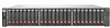
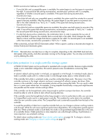
RAID-6 reconstruction behaves as follows: • If one disk fails and a compatible spare is available, the system begins to use that spare to reconstruct the vdisk. If a second disk fails during reconstruction, reconstruction continues until it is complete, regardless of whether a second spare is available. If the spare fails during reconstruction, reconstruction stops. • If two disks fail and only one compatible spare is available, the system waits five minutes for a second spare to become available. After five minutes, the system begins to use that spare to reconstruct one disk in the vdisk (referred to as "fail 2, fix 1" mode). If the spare fails during reconstruction, reconstruction stops. • If two disks fail and two compatible spares are available, the system uses both spares to reconstruct the vdisk. If one of the spares fails during reconstruction, reconstruction proceeds in "fail 2, fix 1" mode. If the second spare fails during reconstruction, reconstruction stops. • If a disk fails during online initialization, the initialization fails. In order to generate the two sets of parity that RAID 6 requires, the controller fails a second disk in the vdisk, which changes the vdisk status to critical, and then assigns that disk as a spare for the vdisk. If a second spare is not available within five minutes, reconstruction proceeds in "fail 2, fix 1" mode. When a disk fails, its Fault/UID LED illuminates amber. When a spare is used as a reconstruction target, its Online/Activity LED illuminates green. NOTE: Reconstruction can take hours or days to complete, depending on the vdisk RAID level and size, disk speed, utility priority, and other processes running on the storage system. You can stop reconstruction only by deleting the vdisk. About data protection in a single-controller storage system A P2000 G3 MSA System can be purchased or operated with a single controller. Because single-controller mode is not a redundant configuration, this section presents some considerations concerning data protection. A volume's default caching mode is write back, as opposed to write through. In write-back mode, data is held in controller cache until it is written to disk. In write-through mode, data is written directly to disk. If the controller fails while in write-back mode, unwritten cache data likely exists. The same is true if the controller enclosure or the target volume's enclosure is powered off without a proper shut down. Data remains in the controller's cache and associated volumes will be missing that data. This can result in data loss or in some cases volume loss; for example, if using snapshot functionality a snap pool might become inaccessible and the master volume could go offline. If the controller can be brought back online long enough to perform a proper shut down, the controller should be able to write its cache to disk without causing data loss. If the controller cannot be brought back online long enough to write its cache data to disk, you can move its CompactFlash cache card to a replacement controller. This enables the cache data to be available when the new controller comes online. The CompactFlash card is externally accessible from the back of the controller. To avoid the possibility of data loss in case the controller fails you can change a volume's caching mode to write through. While this will cause significant performance degradation, this configuration guards against data loss. While write-back mode is much faster, this mode is not guaranteed against data loss in the case of a controller failure. If data protection is more important, use write-through caching; if performance is more important, use write-back caching. For details about caching modes see About volume cache options on page 24. To change a volume's caching mode, see Changing a volume's cache settings on page 55. 34 Getting started
-
 1
1 -
2
-
3
-
4
-
5
-
6
-
7
-
8
-
9
-
10
-
11
-
12
-
13
-
14
-
15
-
16
-
17
-
18
-
19
-
20
-
21
-
22
-
23
-
24
-
25
-
26
-
27
-
28
-
 29
29 -
 30
30 -
 31
31 -
 32
32 -
 33
33 -
 34
34 -
 35
35 -
 36
36 -
 37
37 -
 38
38 -
 39
39 -
40
-
41
-
42
-
43
-
44
-
45
-
46
-
47
-
48
-
49
-
50
-
51
-
52
-
53
-
54
-
55
-
56
-
57
-
58
-
59
-
60
-
61
-
62
-
63
-
64
-
65
-
66
-
67
-
68
-
69
-
70
-
71
-
72
-
73
-
74
-
75
-
76
-
77
-
78
-
79
-
80
-
81
-
82
-
83
-
84
-
85
-
86
-
87
-
88
-
89
-
90
-
91
-
92
-
93
-
94
-
95
-
96
-
97
-
98
-
99
-
100
-
101
-
102
-
103
-
104
-
105
-
106
-
107
-
108
-
109
-
110
-
111
-
112
-
113
-
114
-
115
-
116
-
117
-
118
-
119
-
120
-
121
-
122
-
123
-
124
-
125
-
126
-
127
-
128
-
129
-
130
-
131
-
132
-
133
-
134
-
135
-
136
-
137
-
138
-
139
-
140
-
141
-
142
-
143
-
144
-
145
-
146
-
147
-
148
-
149
-
150
-
151
-
152
-
153
-
154
-
155
-
156
-
157
-
158
-
159
-
160
 |
 |