HP P2000 HP StorageWorks DC Power and Cooling Module Replacement Instructions
HP P2000 Manual
 |
View all HP P2000 manuals
Add to My Manuals
Save this manual to your list of manuals |
HP P2000 manual content summary:
- HP P2000 | HP StorageWorks DC Power and Cooling Module Replacement Instructions - Page 1
. • The Storage Management Utility (SMU) and the Command Line Interface (CLI) can be used to manage the storage enclosure. Tasks in this document demonstrate using the SMU. • For the latest product documentation, see the HP website at http:// www.hp.com/support/manuals. Under the storage banner - HP P2000 | HP StorageWorks DC Power and Cooling Module Replacement Instructions - Page 2
the enclosure as far as it will go (1). 2. Rotate the latch upward to engage the module internal connector (2). Additional information HP StorageWorks Modular Smart Arrays: http://www.hp.com/go/msa HP data storage: http://www.hp.com/storage HP technical support: http://www.hp.com/support HP manuals
-
 1
1 -
 2
2
 |
 |

HP StorageWorks
DC Power and Cooling Module
Replacement Instructions
This document details procedures for replacing a failed
DC power and cooling module in an HP StorageWorks
enclosure.
© Copyright 2009 Hewlett-Packard Development Company, L.P.
First edition: November 2009
The information in this document is subject to change without notice.
Printed in the US
www.hp.com
*500919-002*
About this document
•
Illustrations in this document may show modules or an enclosure that
differ slightly from the devices in your environment.
•
The Storage Management Utility (SMU) and the Command Line Inter-
face (CLI) can be used to manage the storage enclosure. Tasks in
this document demonstrate using the SMU.
•
For the latest product documentation, see the HP website at
h
t
tp://
w
w
w
.hp
.co
m/su
ppo
r
t/man
uals
. Under the storage banner, navigate
to the page for your storage enclosure.
•
Warranties for HP products and services are set forth in the express
warranty statements accompanying such products and services.
Nothing herein should be construed as constituting an additional
warranty. HP shall not be liable for technical or editorial errors or
omissions contained herein. To obtain a copy of the warranty for
this product, see the warranty information website:
h
t
tp://
w
w
w
.hp
.co
m/ go/s
t
o
r
age
w
ar
r
an
t
y
.
Before you begin
Observe the following:
CAUTION:
•
Removing a module from an operational enclosure significantly
changes air flow within the enclosure. Openings must be
populated for the enclosure to cool properly. Leave modules
in the enclosure until ready to install a replacement.
•
Parts can be damaged by electrostatic discharge; use proper
anti-static protection. Keep parts in electrostatic containers
until needed and ensure you are properly grounded when
touching static-sensitive components.
NOTE:
Port-colored (purple) latches on modules mean the module is
hot-swappable. It can be replaced without having to power
down the system.
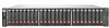
The following illustration shows power and cooling module locations:
2. Power and cooling module 2
1. Power and cooling module 1
Page 1