HP P2015 Service Manual - Page 184
High-voltage contacts check, Checking the print cartridge contacts
 |
UPC - 882780491984
View all HP P2015 manuals
Add to My Manuals
Save this manual to your list of manuals |
Page 184 highlights
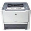
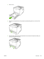
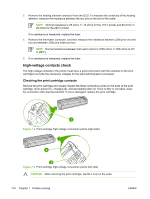
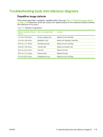
3. Remove the heating element connector from the ECU. To measure the continuity of the heating element, measure the resistance between the two pins at the end of the cable. NOTE Normal resistance is 25 ohms +/- 10 ohms for the 110 V printer and 80 ohms +/20 ohms for the 220 V printer. If no resistance is measured, replace the fuser. 4. Remove the thermistor connector, and then measure the resistance between J206 pins one and two and between J206 pins three and four. NOTE Normal resistance between both pairs of pins is 370K ohms +/- 50K ohms at 20° C (68°F). 5. If no resistance is measured, replace the fuser. High-voltage contacts check The high-voltage contacts in the printer must have a good connection with the contacts on the print cartridge to provide the necessary voltages for the electrophotographic processes. Checking the print cartridge contacts Remove the print cartridge and visually inspect the three connection points on the ends of the print cartridge: drum ground (1), charging (2), and developing roller (3). If one is dirty or corroded, clean the connection with isopropyl alcohol. If one is damaged, replace the print cartridge. Figure 7-2 Print cartridge high-voltage connection points (right side) Figure 7-3 Print cartridge high-voltage connection points (left side) CAUTION After removing the print cartridge, handle it only on the ends. 174 Chapter 7 Problem solving ENWW
-
 1
1 -
2
-
3
-
4
-
5
-
6
-
7
-
8
-
9
-
10
-
11
-
12
-
13
-
14
-
15
-
16
-
17
-
18
-
19
-
20
-
21
-
22
-
23
-
24
-
25
-
26
-
27
-
28
-
29
-
30
-
31
-
32
-
33
-
34
-
35
-
36
-
37
-
38
-
39
-
40
-
41
-
42
-
43
-
44
-
45
-
46
-
47
-
48
-
49
-
50
-
51
-
52
-
53
-
54
-
55
-
56
-
57
-
58
-
59
-
60
-
61
-
62
-
63
-
64
-
65
-
66
-
67
-
68
-
69
-
70
-
71
-
72
-
73
-
74
-
75
-
76
-
77
-
78
-
79
-
80
-
81
-
82
-
83
-
84
-
85
-
86
-
87
-
88
-
89
-
90
-
91
-
92
-
93
-
94
-
95
-
96
-
97
-
98
-
99
-
100
-
101
-
102
-
103
-
104
-
105
-
106
-
107
-
108
-
109
-
110
-
111
-
112
-
113
-
114
-
115
-
116
-
117
-
118
-
119
-
120
-
121
-
122
-
123
-
124
-
125
-
126
-
127
-
128
-
129
-
130
-
131
-
132
-
133
-
134
-
135
-
136
-
137
-
138
-
139
-
140
-
141
-
142
-
143
-
144
-
145
-
146
-
147
-
148
-
149
-
150
-
151
-
152
-
153
-
154
-
155
-
156
-
157
-
158
-
159
-
160
-
161
-
162
-
163
-
164
-
165
-
166
-
167
-
168
-
169
-
170
-
171
-
172
-
173
-
174
-
175
-
176
-
177
-
178
-
 179
179 -
 180
180 -
 181
181 -
 182
182 -
 183
183 -
 184
184 -
 185
185 -
 186
186 -
 187
187 -
 188
188 -
 189
189 -
190
-
191
-
192
-
193
-
194
-
195
-
196
-
197
-
198
-
199
-
200
-
201
-
202
-
203
-
204
-
205
-
206
-
207
-
208
-
209
-
210
-
211
-
212
-
213
-
214
-
215
-
216
-
217
-
218
-
219
-
220
-
221
-
222
-
223
-
224
-
225
-
226
-
227
-
228
-
229
-
230
-
231
-
232
-
233
-
234
-
235
-
236
-
237
-
238
-
239
-
240
-
241
-
242
-
243
-
244
-
245
-
246
-
247
-
248
-
249
-
250
-
251
-
252
-
253
-
254
-
255
-
256
-
257
-
258
-
259
-
260
-
261
-
262
-
263
-
264
-
265
-
266
-
267
-
268
-
269
-
270
-
271
-
272
-
273
-
274
-
275
-
276
-
277
-
278
-
279
-
280
-
281
-
282
-
283
-
284
-
285
-
286
-
287
-
288
-
289
-
290
-
291
-
292
-
293
-
294
-
295
-
296
 |
 |