HP P6300 HP P6300/P6500 EVA Installation Guide (5697-2485, September 2013)
HP P6300 Manual
 |
View all HP P6300 manuals
Add to My Manuals
Save this manual to your list of manuals |
HP P6300 manual content summary:
- HP P6300 | HP P6300/P6500 EVA Installation Guide (5697-2485, September 2013) - Page 1
Enterprise Virtual Array Installation Guide Abstract This guide provides instructions to set up, install, and configure HP P63x0/65x0 EVAs. It is intended for HP P63x0 EVA self-install customers or HP-authorized P65x0 service providers. *5697-2485* HP Part Number: 5697-2485 Published: September - HP P6300 | HP P6300/P6500 EVA Installation Guide (5697-2485, September 2013) - Page 2
a copy of the warranty for this product, see the warranty information website: http://www.hp.com/go/storagewarranty Acknowledgements Microsoft® and Windows® are U.S. registered trademarks of Microsoft Corporation. NOTE: IPv6 is supported on server-based management HP P6000 Command View beginning - HP P6300 | HP P6300/P6500 EVA Installation Guide (5697-2485, September 2013) - Page 3
controller enclosures 32 Verify the operating status of the disk enclosures 33 Verify the operating status of the Fibre Channel switches and adapters 34 Installing Fibre Channel drivers 35 6 Managing the iSCSI or iSCSI/FCoE module using HP P6000 Command View..36 Initializing the storage system - HP P6300 | HP P6300/P6500 EVA Installation Guide (5697-2485, September 2013) - Page 4
Configuring application servers manually 60 Using and monitoring your storage 60 Controller software recovery 60 Installing HP Insight Remote Support software 60 9 Support and other resources 62 Contacting HP...62 HP technical support...62 Subscription service...62 Documentation feedback...62 - HP P6300 | HP P6300/P6500 EVA Installation Guide (5697-2485, September 2013) - Page 5
you: • Develop an installation and configuration plan for your Fibre Channel FC-SAN and/or Ethernet IP-SAN environments. • Review all videos and documentation. NOTE: If also upgrading from P6300/P6500 to P6350/P6550, respectively, see the HP P6000 EVA Upgrade Instructions - P6300 to P6350 or P6500 - HP P6300 | HP P6300/P6500 EVA Installation Guide (5697-2485, September 2013) - Page 6
and both Mez50/Mez75 controllers must be at the same firmware version. General IP-SAN recommendations • For Microsoft Windows Server environments, implement MPIO and HP DSM for NIC fault-tolerance and superior performance. • For other operating systems, where supported, implement NIC bonding in - HP P6300 | HP P6300/P6500 EVA Installation Guide (5697-2485, September 2013) - Page 7
.www1.hp.com/storage/networking/index.html These switches are also referenced in the HP SAN Design Reference Guide, which is also available through this website. Table 1 Minimum recommended switch capabilities for a P63x0/P65x0 EVA-based IP-SAN Switch capability 1 and 10 gigabit Ethernet support - HP P6300 | HP P6300/P6500 EVA Installation Guide (5697-2485, September 2013) - Page 8
switch capabilities for a P63x0/P65x0 EVA-based IP-SAN (continued) Switch capability Description cache among a group of ports (for example, 1 MB of cache per 8 ports), space your used ports appropriately to avoid cache oversubscription. Flow control support IP storage networks are unique in the - HP P6300 | HP P6300/P6500 EVA Installation Guide (5697-2485, September 2013) - Page 9
/FCoE) array. The iSCSI protocol transport is supported at 1 GbE and 10 GbE rates through the 1 GbE iSCSI modules or 10 GbE iSCSI/FCoE modules. Figure 1 (page 10) illustrates the normal multi-protocol data and management connectivity. HP P6000 Command View requires Ethernet access to the 1 GbE iSCSI - HP P6300 | HP P6300/P6500 EVA Installation Guide (5697-2485, September 2013) - Page 10
/FCoE controllers, follow these steps to enable use of HP P6000 Command View management: 1. Configure the iSCSI or iSCSI/FCoE management and data port IP addresses using the CLI. 2. Verify that the iSCSI or iSCSI/FCoE management and data port cables are installed. 3. From the HP P6000 Command View - HP P6300 | HP P6300/P6500 EVA Installation Guide (5697-2485, September 2013) - Page 11
:f4ce:46fb:297c With management zoning enabled, HP P6000 Command View will discover the P6000 system to be managed. Once this connectivity is established, HP P6000 Command View can be used to manage the P6000 system. Proceed to initialize the storage system and then navigate to the Hardware > iSCSI - HP P6300 | HP P6300/P6500 EVA Installation Guide (5697-2485, September 2013) - Page 12
of iSCSI and iSCSI/FCoE initiators For one P63x0/P65x0 EVA controller, and assuming a redundant configuration, HP P6000 Command View supports 256 initiators and 255 LUNs, plus LUN 0. On the iSCSI/FCoE modules, HP P6000 Command View supports 1024 initiators, 1024 LUNs, and 256 LUNs per virtual port - HP P6300 | HP P6300/P6500 EVA Installation Guide (5697-2485, September 2013) - Page 13
iSCSI/FCoE modules prior to presenting LUNs using HP P6000 Command View. Number of paths required per initiator After establishing the number of initiators, determine how many paths are required by each initiator. The number of connections per iSCSI controller is finite, and every initiator login - HP P6300 | HP P6300/P6500 EVA Installation Guide (5697-2485, September 2013) - Page 14
accept the current value. If you wish to terminate this process before reaching the end of the list press 'q' or 'Q' and the ENTER key to do so. CHAP can use either the CLI or HP P6000 Command View to add the iSCSI initiator IQN: • CLI: Use the initiator add command. MEZ75 (admin) #> initiator add - HP P6300 | HP P6300/P6500 EVA Installation Guide (5697-2485, September 2013) - Page 15
manually set chap CLI command to determine if end of the list press 'q' or hp:fcgw.mez75.1 1 iqn.2004-09.com.hp:fcgw.mez75.1 2 iqn.2004-09.com.hp:fcgw.mez75.1.01.5001438004c68968 3 iqn.2004-09.com.hp:fcgw.mez75.1.01.5001438004c6896c 4 iqn.2004-09.com.hp process before reaching the end of the list press - HP P6300 | HP P6300/P6500 EVA Installation Guide (5697-2485, September 2013) - Page 16
, and then select Add Host). 3. Enable CHAP for the iSCSI or iSCSI/FCoE port using HP P6000 Command View or the CLI. • If using HP P6000 Command View: a. Choose the appropriate iSCSI or iSCSI/FCoE controller, select the IP Ports tab, and then select the appropriate IP port. b. Under Security, select - HP P6300 | HP P6300/P6500 EVA Installation Guide (5697-2485, September 2013) - Page 17
Click OK. f. Click the Discovery tab and when manually discovering iSCSI target portals: i. Click Add under storage efficiency. RAID levels Vraid is the HP term for the implementation of RAID storage on EVAs. Vraid is also referred to as redundancy in HP management software. Virtual disks with HP - HP P6300 | HP P6300/P6500 EVA Installation Guide (5697-2485, September 2013) - Page 18
View, HP Command View EVAPerf, HP Storage System Scripting Utility, SMI-S EVA) are installed. Server-based management is applicable to all EVA models. • Array-based management-The P63x0/P65x0 EVAs are shipped with HP P6000 Command View pre-installed on the management module within the controller - HP P6300 | HP P6300/P6500 EVA Installation Guide (5697-2485, September 2013) - Page 19
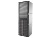
supplies in your installation. For power consumption specifications, see the QuickSpecs document at: http://www.hp.com/go/P6000 Remove product from packaging 1. Remove product from boxes. 2. Verify that contents match your expectations and site requirements. • P63x0 EVA controller enclosure should - HP P6300 | HP P6300/P6500 EVA Installation Guide (5697-2485, September 2013) - Page 20
, two power supply modules, two fan modules, and two battery modules installed. ◦ Rack mounting hardware ◦ Two 2.0 meter SAS Y-cables ◦ Two power cords ◦ Installation documentation ◦ XCS controller software recovery CD • Each FC disk enclosure should contain: ◦ A minimum of one 2U M6612 or M6625 - HP P6300 | HP P6300/P6500 EVA Installation Guide (5697-2485, September 2013) - Page 21
Rail kits • Controller and disk enclosures • Disk drives IMPORTANT: The P65x0 EVA requires installation service by an HP-authorized service provider. For more information, contact HP technical support in North America at 1-800-474-6836. Outside North America, call HP technical support at the nearest - HP P6300 | HP P6300/P6500 EVA Installation Guide (5697-2485, September 2013) - Page 22
configured for expansion Attach the brackets for a longer chassis If you are installing a longer chassis into your cabinet, such as for the controller enclosure, you must remove the shipping retaining bracket and install the smaller brackets supplied in the accessory kit. NOTE: A No. 2 Phillips - HP P6300 | HP P6300/P6500 EVA Installation Guide (5697-2485, September 2013) - Page 23
the new bracket Figure 8 Attaching brackets to rail 3. Repeat Step 1 and Step 2 for the remaining rail. Figure 9 (page 23) shows the disk enclosure rail. Figure 9 Disk enclosure rail Attach the rails NOTE: The left and right rails are designated by the letters R (right) and L (left) or the words - HP P6300 | HP P6300/P6500 EVA Installation Guide (5697-2485, September 2013) - Page 24
injury or damage if the rack tips over. To install the controller enclosure rails: NOTE: Although the disk enclosure rails do not have scissor latches, you can use these steps as a guideline to install the disk enclosure rails. 1. Insert the rear end of the rail into the inside back of the rack - HP P6300 | HP P6300/P6500 EVA Installation Guide (5697-2485, September 2013) - Page 25
push the end of the disk enclosures can either be large form factor (LFF), supporting 12 disk drives, or small form factor (SFF), supporting 25 disk drives. The disk enclosures shown in this section may not look the same as those you are installing. To install disk and controller enclosures: Install - HP P6300 | HP P6300/P6500 EVA Installation Guide (5697-2485, September 2013) - Page 26
it into the rack (Figure 13 (page 26)). Figure 13 Installing an enclosure (view from front of rack) 2. Continue sliding the enclosure into the rack to strip the screws. Figure 14 Securing the rear of the enclosure in the rack (view from front of rack) 3. At the rear of the rack, loosen the screw on - HP P6300 | HP P6300/P6500 EVA Installation Guide (5697-2485, September 2013) - Page 27
Figure 15 Securing the rear of the enclosure (view from rear of rack) 4. Repeat Step 1 through Step 3 to install the controller enclosures. Installing the disk drives into the drive bays After the disk enclosures are secured in the rack, install the disk drives into the drive bays. Drives must be - HP P6300 | HP P6300/P6500 EVA Installation Guide (5697-2485, September 2013) - Page 28
is too heavy to lift safely. • Movement of an enclosure during installation might damage the internal storage media of installed disk drives. • Follow industry-standard practices when handling disk drives. Internal storage media can be damaged when drives are shaken, dropped, or roughly placed - HP P6300 | HP P6300/P6500 EVA Installation Guide (5697-2485, September 2013) - Page 29
• Touching the end of a cable can damage the cable or cause performance problems, including intermittent difficulties accessing the storage. • Whenever a cable is not connected, replace the protective covers on the ends of the cable. • Make certain that the cables are installed and supported so that - HP P6300 | HP P6300/P6500 EVA Installation Guide (5697-2485, September 2013) - Page 30
the P63x0/P65x0 EVA" (page 66) for examples of connecting servers and switches to the array in server-based management and array-based management configurations. Labeling cables using labeling kit A labeling kit is provided with the disk enclosure. Label both ends of each cable using the materials - HP P6300 | HP P6300/P6500 EVA Installation Guide (5697-2485, September 2013) - Page 31
power sources fails, due to a pulled cable or tripped breaker. The remaining power source can power the EVA until the failed power source is restored your storage subsystem. For more information about power sources, see the HP P63x0/P65x0 Enterprise Virtual Array User Guide. Connecting the power - HP P6300 | HP P6300/P6500 EVA Installation Guide (5697-2485, September 2013) - Page 32
For cabling procedures, see "Cabling the P63x0/P65x0 EVA" (page 66). Power on the devices Power on best practices Observe the following best practices before powering up the array for the first time: • Install the controller enclosure. • Install the disk enclosures. • Install disk drives in the disk - HP P6300 | HP P6300/P6500 EVA Installation Guide (5697-2485, September 2013) - Page 33
that the disk enclosures and disk drives are operating properly, view the enclosure and disk drive LEDs and compare them with the patterns shown in Table 5 (page 34). For more information on the disk enclosure status LEDs, see the HP P63x0/P65x0 Enterprise Virtual Array User Guide. Verify the - HP P6300 | HP P6300/P6500 EVA Installation Guide (5697-2485, September 2013) - Page 34
, see the documentation that came with the switch for help. Optional Step: If you will be using Fibre Channel to attach the array to your existing servers, you must install Fibre Channel adapters in those servers and test the Fibre Channel adapters prior to installing HP P6000 Command View. Ensure - HP P6300 | HP P6300/P6500 EVA Installation Guide (5697-2485, September 2013) - Page 35
Fibre Channel drivers. Older PSPs will not have current drivers, so ensure your driver version are current. For other operating systems, load the drivers as directed in "Configuring application servers" in the HP P63x0/P65x0 Enterprise Virtual Array User Guide. Installing Fibre Channel drivers 35 - HP P6300 | HP P6300/P6500 EVA Installation Guide (5697-2485, September 2013) - Page 36
array date and time. • Enter a console LUN ID. • Select a disk failure protection level. For complete information on initializing the storage system, see the HP P6000 Command View User Guide or the associated HP P6000 Command View online help. Configuring the iSCSI and iSCSI/FCoE module management - HP P6300 | HP P6300/P6500 EVA Installation Guide (5697-2485, September 2013) - Page 37
address of 192.168.0.76 port 2372, mask 255.255.255.0, and controller 2's module will default to 192.168.0.82 port 2372, mask 255. static IP addresses for the telnet management ports. Figure 21 P6000 iSCSI module management ports and P6000 fabrics 1. Fibre Channel fabric A 2. Fibre Channel fabric B - HP P6300 | HP P6300/P6500 EVA Installation Guide (5697-2485, September 2013) - Page 38
If you wish to terminate this process before reaching the end of the list press 'q' or 'Q' and the ENTER key to do so. WARNING: The following command might cause a loss of connections to the MGMT port. Port Information 38 Managing the iSCSI or iSCSI/FCoE module using HP P6000 Command View - HP P6300 | HP P6300/P6500 EVA Installation Guide (5697-2485, September 2013) - Page 39
Static 10.6.6.130 255.255.240.0 10.6.4.200 Disabled Up f4-ce-46-fb-0a-40 MEZ75 (admin) #> help General Command Set: admin [ begin | end | start | stop | cancel ] beacon [ on | off ] clear [ logs | stats ] date [ ] exit fru [ restore | save ] help history image [ cleanup - HP P6300 | HP P6300/P6500 EVA Installation Guide (5697-2485, September 2013) - Page 40
reset mappings operation only clears user defined LUN mappings, and EVA. HP P6000 Command View instantiates host objects which contain Fibre Channel ports, with consideration of multipath LUN presentation through both controllers. If you are implementing FCoE connectivity, zoning the FCoE storage - HP P6300 | HP P6300/P6500 EVA Installation Guide (5697-2485, September 2013) - Page 41
Figure 23 P6000 iSCSI configuration with one or four HP P6000 Command View hosts (256 or 1024 LUNs) Fibre Channel zoning 41 - HP P6300 | HP P6300/P6500 EVA Installation Guide (5697-2485, September 2013) - Page 42
iSCSI configuration with four HP P6000 Command View hosts (1024 LUNs) HP P6000 Command View discovery The iSCSI and iSCSI/FCoE module FC ports are logged in to the array when the controllers are powered on and in an active state. Now you can use HP P6000 Command View to perform device discovery - HP P6300 | HP P6300/P6500 EVA Installation Guide (5697-2485, September 2013) - Page 43
class subnet on the telnet management ports for consistent connectivity and to support peer pairing for persistent reservations. If an iSCSI controller pairing failure is displayed in HP P6000 Command View, use the following CLI commands to help repair the issue and possibly avoid having to remove - HP P6300 | HP P6300/P6500 EVA Installation Guide (5697-2485, September 2013) - Page 44
Figure 27 iSCSI Host 01 properties Figure 28 iSCSI/FCoE VPGO, Host 01 properties 44 Managing the iSCSI or iSCSI/FCoE module using HP P6000 Command View - HP P6300 | HP P6300/P6500 EVA Installation Guide (5697-2485, September 2013) - Page 45
Figure 29 iSCSI/FCoE VPG1, Host 02 properties Figure 30 iSCSI/FCoE VPG2, Host 03 properties Figure 31 iSCSI/FCoE VPG3, Host 04 properties HP P6000 Command View discovery 45 - HP P6300 | HP P6300/P6500 EVA Installation Guide (5697-2485, September 2013) - Page 46
a LUN to multiple FCoE hosts, which are under common multipathing management. HP P6000 Command View supports instantiating FC, iSCSI, and FCoE host types (as shown in Figure 33 (page 46)). Simultaneous presentation of a virtual disk to different host types, spanning multiple protocols is not - HP P6300 | HP P6300/P6500 EVA Installation Guide (5697-2485, September 2013) - Page 47
Example 2 iSCSI/FCoE module IQN iqn.2004-09.com.hp:fcgw.mez75.2.02.5001438004448a09 Figure 34 (page 47) shows the two levels of FCoE LUN mapping. Figure 34 iSCSI/FCoE two level LUN mapping presentation Figure 35 (page 48) shows the two levels of iSCSI LUN mapping. HP P6000 Command View discovery 47 - HP P6300 | HP P6300/P6500 EVA Installation Guide (5697-2485, September 2013) - Page 48
controller and the failover option (Figure 36 (page 48)). Figure 36 iSCSI/FCoE preferred path optimization While presenting the Vdisk to a Windows 2012 host, selected Microsoft Windows 2012 from the Operating System menu. 48 Managing the iSCSI or iSCSI/FCoE module using HP P6000 Command View - HP P6300 | HP P6300/P6500 EVA Installation Guide (5697-2485, September 2013) - Page 49
in the Navigation pane to display the iSCSI Controller Properties window (Figure 38 (page 50). 2. Select the IP Ports tab. 3. Set the IP attributes for each iSCSI port and enable the port (Figure 39 (page 50)). Both IPv4 and IPv6 are supported for configuration. Security and integrity may be - HP P6300 | HP P6300/P6500 EVA Installation Guide (5697-2485, September 2013) - Page 50
and 2) with the initiator event logs and to assist in troubleshooting. 1. Select the iSCSI controller in the Navigation pane. 2. Select Set Options, and then select Set time options from the iSCSI Controller Options menu. HP P6000 Command View provides three options for setting the time as shown in - HP P6300 | HP P6300/P6500 EVA Installation Guide (5697-2485, September 2013) - Page 51
http://www.hp.com/support/software Updating the iSCSI or iSCSI/FCoE module firmware is separate from upgrading the XCS controller software, but the process is the same (using the Code Load function in HP P6000 Command View). NOTE: HP recommends that you update one module at a time to avoid a service - HP P6300 | HP P6300/P6500 EVA Installation Guide (5697-2485, September 2013) - Page 52
the iSCSI or iSCSI/FCoE modules through HP P6000 Command View is not supported. You must use the CLI to shut down the modules and then power cycle the array to power on the modules after the shutdown. To restart a module: 1. Select the iSCSI controller in the Navigation pane. 2. Select Shutdown on - HP P6300 | HP P6300/P6500 EVA Installation Guide (5697-2485, September 2013) - Page 53
the iSCSI or iSCSI/FCoE module to be in a factory reset state. If a new controller is installed, the full configuration can be restored and no reconfiguration is required. When using HP P6000 Command View to uninitialize a P63x0 or P65x0 array, the iSCSI or iSCSI/FCoE modules are issued reset - HP P6300 | HP P6300/P6500 EVA Installation Guide (5697-2485, September 2013) - Page 54
45 Locate button in iSCSI Controller Properties 3. Select Locate ON on the Locate Hardware Device window (Figure 46 (page 54)). Figure 46 Locate hardware device NOTE: The flashing blue Locate LED turns off after 15 minutes. 54 Managing the iSCSI or iSCSI/FCoE module using HP P6000 Command View - HP P6300 | HP P6300/P6500 EVA Installation Guide (5697-2485, September 2013) - Page 55
Controller options P6000 Command View supports re-configuration of the iSCSI and iSCSI/FCoE modules by first providing the option to remove the controller each removed controller prior to returning and selecting the Discover or Add iSCSI Devices tabs. This allows P6000 Command View and the user to - HP P6300 | HP P6300/P6500 EVA Installation Guide (5697-2485, September 2013) - Page 56
the P63x0 EVA or P65x0 EVA storage system using HP P6000 Command View. For more information, see "Initializing the storage system" (page 36). 2. If it is currently connected, disconnect the public network LAN cable from the back of the management module in the controller enclosure. 3. Press - HP P6300 | HP P6300/P6500 EVA Installation Guide (5697-2485, September 2013) - Page 57
log in as an HP EVA administrator. HP recommends that you either change or delete the default IPv4 and IPv6 addresses to avoid duplicate address detection issues on your network. The default user name is admin. No password is required during the initial setup. The HP P6000 Control Panel GUI appears - HP P6300 | HP P6300/P6500 EVA Installation Guide (5697-2485, September 2013) - Page 58
not change this mode, the storage system will be unable to communicate with your server. Use the HP P6000 Control Panel to change the default operating mode. NOTE: Change your browser settings for the HP P6000 Control Panel as described in the HP P6000 Command View Installation Guide. You must have - HP P6300 | HP P6300/P6500 EVA Installation Guide (5697-2485, September 2013) - Page 59
is desired. 8. Close the HP P6000 Control Panel and remove the Ethernet cable from the server, however, you may want to retain access to the ABM to initialize the storage cell, for example. Accessing the HP P6000 Control Panel through HP P6000 Command View 1. Select the storage system you want to - HP P6300 | HP P6300/P6500 EVA Installation Guide (5697-2485, September 2013) - Page 60
HP P6000 Command View configuration. Configuring application servers manually For information about manually configuring application servers, see the HP P63x0/P65x0 Enterprise Virtual Array User Guide. See "Related information" (page 62) for the document location. Using and monitoring your storage - HP P6300 | HP P6300/P6500 EVA Installation Guide (5697-2485, September 2013) - Page 61
software provides comprehensive remote monitoring and proactive service support for nearly all HP servers, storage, network, and SAN environments, plus selected non-HP servers that have a support obligation with HP. It is integrated with HP Systems Insight Manager. A dedicated server is recommended - HP P6300 | HP P6300/P6500 EVA Installation Guide (5697-2485, September 2013) - Page 62
For documents referenced in this guide, see the Manuals page on the Business Support Center website: http://www.hp.com/support/manuals In the Storage section, click Disk Storage Systems or Storage Software and then select your product. Websites • HP: http://www.hp.com • HP Storage: http://www.hp.com - HP P6300 | HP P6300/P6500 EVA Installation Guide (5697-2485, September 2013) - Page 63
• HP Software Downloads: http://www.hp.com/support/downloads • HP Software Depot: http://www.software.hp.com • HP Single Point of Connectivity Knowledge (SPOCK): http://www.hp.com/storage/spock • HP SAN manuals: http://www.hp.com/go/sdgmanuals Typographic conventions Table 6 Document conventions - HP P6300 | HP P6300/P6500 EVA Installation Guide (5697-2485, September 2013) - Page 64
. • In multiple-rack installations, fasten racks together securely. • Extend only one rack component at a time. Racks can become unstable if more than one component is extended. Location of WWN and serial number For service and support purposes, the location of the controller serial number, world - HP P6300 | HP P6300/P6500 EVA Installation Guide (5697-2485, September 2013) - Page 65
Figure 51 Location of WWN and serial number for bundled products Location of WWN and serial number 65 - HP P6300 | HP P6300/P6500 EVA Installation Guide (5697-2485, September 2013) - Page 66
describes cabling instructions for the P63x0/P65x0 EVA. If you are using the P63x0/P65x0 EVA Fibre Channel controller and plan to configure it with an external iSCSI device, see the HP MPX200 Multifunction Router User Guide, which is available at: http://www.hp.com/support/manuals Under storage - HP P6300 | HP P6300/P6500 EVA Installation Guide (5697-2485, September 2013) - Page 67
redundant paths for fault tolerance. Port P1 on I/O module A of the top disk enclosure and port P2 on I/O module A of the bottom disk enclosure represent the beginning and end of the path. Figure 52 Cabling the first redundant path Connecting P63x0 EVA controllers to the disk enclosures (2C6D) 67 - HP P6300 | HP P6300/P6500 EVA Installation Guide (5697-2485, September 2013) - Page 68
the controller enclosure to I/O module B (red ports) on the top and bottom disk enclosures. This cabling represents the second redundant path (P1 on I/O module B of the top disk enclosure and P2 on I/O module B of the bottom disk enclosure). Figure 53 Cabling the second redundant path 68 Cabling the - HP P6300 | HP P6300/P6500 EVA Installation Guide (5697-2485, September 2013) - Page 69
4. Connect the disk enclosures together to complete the connectivity. Figure 54 Cabling the disk enclosures Connecting P63x0 EVA controllers to the disk enclosures (2C6D) 69 - HP P6300 | HP P6300/P6500 EVA Installation Guide (5697-2485, September 2013) - Page 70
Figure 55 (page 70) shows the complete cabling for the P63x0 EVA 2C6D configuration. Figure 55 Complete cabling for the P63x0 EVA 2C6D 70 Cabling the P63x0/P65x0 EVA - HP P6300 | HP P6300/P6500 EVA Installation Guide (5697-2485, September 2013) - Page 71
P65x0 EVA controllers to the disk enclosures (2C6D) Y-cables (see Figure 56 (page 71)) are used to connect the P65x0 and enable each controller port to act as two ports. The Y-cables provide connectivity to each SAS domain (indicated as DP-1 and DP-2 on the cables in the diagrams). The Y-cable - HP P6300 | HP P6300/P6500 EVA Installation Guide (5697-2485, September 2013) - Page 72
Figure 57 Connecting the redundant paths in each SAS domain 72 Cabling the P63x0/P65x0 EVA - HP P6300 | HP P6300/P6500 EVA Installation Guide (5697-2485, September 2013) - Page 73
3. Connect the disk enclosures in each group of disk enclosures together to complete the connectivity. Figure 58 Cabling the disk enclosures together Connecting P65x0 EVA controllers to the disk enclosures (2C6D) 73 - HP P6300 | HP P6300/P6500 EVA Installation Guide (5697-2485, September 2013) - Page 74
Figure 59 (page 74) shows the complete cabling for the P65x0 EVA 2C6D configuration. Figure 59 Complete cabling for the P65x0 EVA 2C6D 74 Cabling the P63x0/P65x0 EVA - HP P6300 | HP P6300/P6500 EVA Installation Guide (5697-2485, September 2013) - Page 75
of the P65x0. Figure 60 Cabling the controller to front end component-Fibre Channel to switch detail view with server-based management 1. File server 2. Management server 3. Database server 4. Fiber channel switch 5. LED status indicators for cabling connections to disk enclosures. See Figure 55 - HP P6300 | HP P6300/P6500 EVA Installation Guide (5697-2485, September 2013) - Page 76
61 Cabling the controller to front end components-Fibre Channel to switch detail view with array-based management 1. File server 2. Database server 3. Fiber channel switch 4. LED status indicators for cabling connections to disk enclosures. See Figure 55 (page 70) and Figure 59 (page 74) for cabling - HP P6300 | HP P6300/P6500 EVA Installation Guide (5697-2485, September 2013) - Page 77
Figure 62 Cabling the controller to front end components-Direct Fibre Channel to servers with server-based management 1. Management server 2. Database server 3. LED status indicators for cabling connections to disk enclosures. See Figure 55 (page 70) and Figure 59 (page 74) for cabling connections. - HP P6300 | HP P6300/P6500 EVA Installation Guide (5697-2485, September 2013) - Page 78
server 2. Database server 3. Indicates cabling connections to disk enclosures. See Figure 55 (page 70) and Figure 59 (page 74) for cabling connections. iSCSI and iSCSI/FCoE You can connect the front of the P63x0/P65x0 EVA iSCSI or iSCSI/FCoE controllers to Ethernet, SAN, or FCoE switches as shown - HP P6300 | HP P6300/P6500 EVA Installation Guide (5697-2485, September 2013) - Page 79
64 P63x0 iSCSI and FC connections 1. Isolated servers 4. SAN switches 2. Datacenter servers with FC and Ethernet 5. Management server running HP P6000 Command View adapters 3. Ethernet switches 6. Cabling connections to disk enclosures Connecting the P63x0/P65x0 EVA to servers and switches 79 - HP P6300 | HP P6300/P6500 EVA Installation Guide (5697-2485, September 2013) - Page 80
connections 1. Isolated servers with converged network 4. Ethernet switches adapters 2. Datacenter servers with converged network adapters 5. Management server running HP P6000 Command View 3. Converged network switches 6. Cabling connections to disk enclosures 80 Cabling the P63x0/P65x0 EVA - HP P6300 | HP P6300/P6500 EVA Installation Guide (5697-2485, September 2013) - Page 81
servers 2. Datacenter servers with converged network adapters 3. Ethernet switches 4. Converged network switches 5. Management server running HP P6000 Command View with a converged network adapter 6. Cabling connections to disk enclosures Connecting the P63x0/P65x0 EVA to servers and switches 81 - HP P6300 | HP P6300/P6500 EVA Installation Guide (5697-2485, September 2013) - Page 82
Figure 67 P65x0 iSCSI/FCoE connections 1. Blade servers with converged network adapters 2. Pass-through or FIP snooping DCB switches 3. DCB Ethernet/FCoE switches 4. Ethernet network 82 Cabling the P63x0/P65x0 EVA
-
 1
1 -
 2
2 -
 3
3 -
 4
4 -
 5
5 -
 6
6 -
 7
7 -
8
-
9
-
10
-
11
-
12
-
13
-
14
-
15
-
16
-
17
-
18
-
19
-
20
-
21
-
22
-
23
-
24
-
25
-
26
-
27
-
28
-
29
-
30
-
31
-
32
-
33
-
34
-
35
-
36
-
37
-
38
-
39
-
40
-
41
-
42
-
43
-
44
-
45
-
46
-
47
-
48
-
49
-
50
-
51
-
52
-
53
-
54
-
55
-
56
-
57
-
58
-
59
-
60
-
61
-
62
-
63
-
64
-
65
-
66
-
67
-
68
-
69
-
70
-
71
-
72
-
73
-
74
-
75
-
76
-
77
-
78
-
79
-
80
-
81
-
82
 |
 |

HP P63x0/P65x0 Enterprise Virtual Array
Installation Guide
Abstract
This guide provides instructions to set up, install, and configure HP P63x0/65x0 EVAs. It is intended for HP P63x0 EVA
self-install customers or HP-authorized P65x0 service providers.
*5697-2485*
HP Part Number: 5697-2485
Published: September 2013
Edition: 5