HP Pavilion 6600 HP Pavilion PCs - (English) Seagate Hard Drive U Series 8 Ins
HP Pavilion 6600 - Desktop PC Manual
 |
View all HP Pavilion 6600 manuals
Add to My Manuals
Save this manual to your list of manuals |
HP Pavilion 6600 manual content summary:
- HP Pavilion 6600 | HP Pavilion PCs - (English) Seagate Hard Drive U Series 8 Ins - Page 1
by-step instructions for your system, run motherboard (see your computer manual for connector locations). ! Caution. Align pin 1 on the motherboard supports capacities up to 8.4 Gbytes only. To access the full capacity of the drive, use LBA mode. 4. Save and exit the system setup program. BIOS - HP Pavilion 6600 | HP Pavilion PCs - (English) Seagate Hard Drive U Series 8 Ins - Page 2
Disk Manager will guide you through the installation process. 4. Proceed to the section on "Loading the Operating System." Installing a Slave problem, contact your dealer or visit www.seagate.com to download SeaTools disc diagnostics software and more troubleshooting advice. Seagate Support Services
-
 1
1 -
 2
2
 |
 |
U8
Family Installation Guide
ST34313A, ST38410A, ST313021A, ST317221A
The Easiest Way to Install Your Drive
DiscWizard
is Seagate’s exclusive Windows program that is included with
your drive for easy drive installation. You can use this software if you
already have a bootable hard drive in your computer and you are running
Windows 98 or Windows 95.
For customized step-by-step instructions for your system, run DiscWizard
before
installing your drive.
To run DiscWizard:
•
Select Run from the Windows Start menu and type
x
:\setup
, where
x
is
the drive letter of your diskette or CD-ROM.
If you cannot run DiscWizard,
follow the instructions on this installation
sheet to install and configure your drive.
What You Need
•
Phillips screwdriver and four 6-32 UNC drive mounting screws
•
A standard 40-pin ATA interface cable,
or
an 80-conductor cable to run
Ultra ATA 66 (max length: 18 inches)
•
An unused drive power cable for your new drive
Ultra ATA/66 Requirements
The drive can support transfer rates up to 66 Mbytes per second
(UDMA 4) in Ultra ATA/66 mode. For your drive to run in this mode, you
need the following:
•
A computer that supports UDMA modes 3 and 4
•
A 40-pin 80-conductor cable (available from your dealer)
•
A software utility to confirm and activate Ultra ATA/66. Seagate
®
provides
a utility called UATA66.exe that is included on your CD, or you can
download it from our Web site at www.seagate.com.
•
The Windows 98 operating system
Handling Precautions
Disc drives are extremely fragile.
Do not
drop or jar the drive.
Keep the drive in the protective SeaShell
container until you are
ready to install it. This will minimize handling damage.
The drive is enclosed in a black, flexible cover called a SeaShield
®
.
Do not remove this permanent cover—it protects the drive from
electrostatic discharge (ESD) and minor impact damage.
Protect your drive from static discharge by wearing a grounded wrist
strap throughout the installation process.
Always handle the drive by the edges or frame.
Do not apply pressure or attach labels to the circuit board or the
top of the drive.
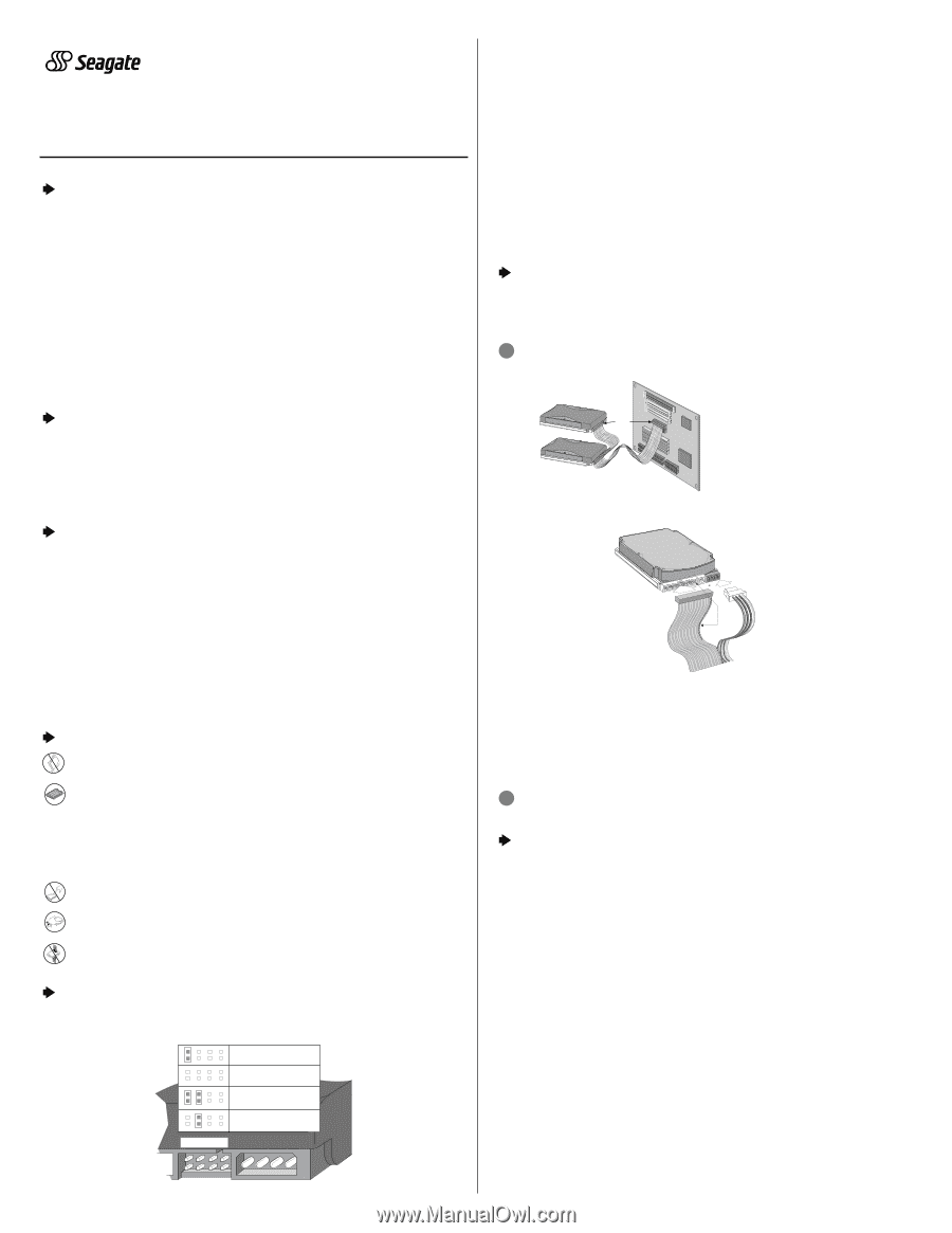
Setting the Jumpers
Refer to the jumper settings below to configure the drive for your system.
•
Master or single-drive:
The drive is shipped configured for a master
or a single-drive with a jumper set on pins 7 and 8.
•
Drive is slave:
To configure the drive as a slave, or second drive on
the cable, remove all the jumpers.
•
Master with non-ATA compatible slave:
Use this setting if the slave
drive is not recognized. To enable this option, configure the master drive
with a jumper set on pins 5 and 6 and pins 7 and 8.
•
Cable-select:
Computers that use cable-select determine the master
and slave drives by selecting or deselecting pin 28, CSEL, on the
interface bus. To enable cable select, set a jumper on pins 5 and 6.
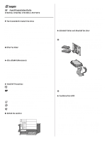
Attaching Cables and Mounting the Drive
1.
Attach one end of the drive interface cable to the interface connector
on your computer’s motherboard
(see your computer manual for
connector locations).
!
Caution.
Align pin 1 on the motherboard connector with pin 1 on
your drive connector. Pin 1 is marked by a stripe on one side of the cable.
2.
Attach the interface connector and the power connector to the drive.
Note.
You can mount the drive in any orientation. Usually it is mounted
with the circuit board down.
3.
Secure the drive in the computer using four 6-32 UNC mounting
screws in either the side-mounting or bottom-mounting holes. Insert
the screws no more than 0.20 inch (5.08 mm) into the bottom-mounting
holes and no more than 0.14 inch (3.55 mm) into the side-mounting holes.
!
Caution.
Do not overtighten the screws or use metric screws. This
may damage the drive.
Configuring the BIOS
For your computer to recognize your new drive, configure your
computer’s BIOS as follows:
1
. Run the system setup program.
2
. Enable LBA mode and UDMA mode, if available.
3
. Select the auto-detect option. If this is not available, select “User-
defined drive type” and enter the CHS (cylinder, head, sectors)
parameters for your drive from the table listed below. The CHS
addressing supports capacities up to 8.4 Gbytes only. To access the
full capacity of the drive, use LBA mode.
4.
Save and exit the system setup program.
BIOS Settings
CHS Mode
LBA Mode
Drive Model
Cylinders
Heads
Sectors
Total Sectors*
ST34313A
8,944
15
63
8,452,080
ST38410A
16,383
16
63
16,841,664
ST313021A
16,383
16
63
25,434,228
ST317221A
16,383
16
63
33,683,328
*One sector equals 512 bytes.
Publication Number: SG35236-001, Rev. B
Pin 1
Interface
connector
Power
connector
Computer
Motherboard
Pin 1
Master
Slave
Note.
If you are using a 40-pin 80-conductor
cable, attach the
blue
connector to the
motherboard, the
black
connector to the
master drive, and the
grey
connector
to the slave.
Options jumper block (J8)
Drive is slave
Cable select
Master with a non-ATA-
compatible slave
Master or single drive
2
6
8
4
1
7
5
3