HP Pro 3010 Maintenance & Service Guide: HP Pro 3000/3010/3080 Business PC
HP Pro 3010 - Microtower PC Manual
 |
View all HP Pro 3010 manuals
Add to My Manuals
Save this manual to your list of manuals |
HP Pro 3010 manual content summary:
- HP Pro 3010 | Maintenance & Service Guide: HP Pro 3000/3010/3080 Business PC - Page 1
Maintenance & Service Guide HP Pro 3000 Business PCs HP Pro 3010 Business PCs HP Pro 3080 Business PCs - HP Pro 3010 | Maintenance & Service Guide: HP Pro 3000/3010/3080 Business PC - Page 2
may be photocopied, reproduced, or translated to another language without the prior written consent of Hewlett-Packard Company. Maintenance & Service Guide HP Pro 3000 Business PCs HP Pro 3010 Business PCs HP Pro 3080 Business PCs First Edition (November 2009) Document Part Number: 597662-001 - HP Pro 3010 | Maintenance & Service Guide: HP Pro 3000/3010/3080 Business PC - Page 3
About This Book WARNING! Text set off in this manner indicates that failure to follow directions could result in bodily harm or loss of life. CAUTION: Text set off in this manner indicates that failure to follow directions could result in damage to equipment or loss of information. NOTE: Text set - HP Pro 3010 | Maintenance & Service Guide: HP Pro 3000/3010/3080 Business PC - Page 4
iv About This Book - HP Pro 3010 | Maintenance & Service Guide: HP Pro 3000/3010/3080 Business PC - Page 5
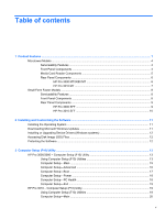
of contents 1 Product Features ...1 Microtower Models ...4 Serviceability Features ...4 Front Panel Components ...4 Media Card Reader Components 5 Rear Panel Components ...6 HP Pro 3000 MT/3080 MT 6 HP Pro 3010 MT 7 Small Form Factor Models ...8 Serviceability Features ...8 Front Panel Components - HP Pro 3010 | Maintenance & Service Guide: HP Pro 3000/3010/3080 Business PC - Page 6
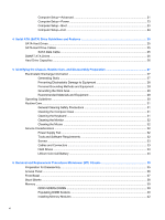
...32 Cleaning the Mouse ...32 Service Considerations ...32 Power Supply Fan ...32 Tools and Software Requirements 32 Screws ...33 Cables and Connectors ...33 Hard Drives ...33 Lithium Coin Cell Battery 34 6 Removal and Replacement Procedures Microtower (MT) Chassis 35 Preparation for Disassembly - HP Pro 3010 | Maintenance & Service Guide: HP Pro 3000/3010/3080 Business PC - Page 7
...49 Cable Connections ...50 HP Pro 3000/3080 50 HP Pro 3010 ...51 Drives ...52 Drive HP/Kensington MicroSaver Security Cable Lock 79 Padlock ...79 HP Business PC Security Lock 80 Hood Sensor ...82 HP Chassis Security Kit ...83 7 Removal and Replacement Procedures Small Form Factor (SFF - HP Pro 3010 | Maintenance & Service Guide: HP Pro 3000/3010/3080 Business PC - Page 8
Cable Management ...99 Cable Connections ...100 HP Pro 3000/3080 100 HP Pro 3010 ...100 Drives ...101 Drive Positions ... a Security Lock ...129 HP/Kensington MicroSaver Security Cable Lock 129 Padlock ...129 HP Business PC Security Lock 130 Hood Sensor ...132 HP Chassis Security Kit 133 Appendix - HP Pro 3010 | Maintenance & Service Guide: HP Pro 3000/3010/3080 Business PC - Page 9
Problems 169 Solving Internet Access Problems ...170 Solving Software Problems ...172 Interpreting POST Audible Codes ...173 Resetting the Password Jumper ...174 Resetting the CMOS Jumper ...175 Contacting Customer Support ...176 Appendix D Specifications ...177 Microtower ...177 Small Form Factor - HP Pro 3010 | Maintenance & Service Guide: HP Pro 3000/3010/3080 Business PC - Page 10
x - HP Pro 3010 | Maintenance & Service Guide: HP Pro 3000/3010/3080 Business PC - Page 11
chassis are available-microtower and small form factor. HP Pro Business PC features vary depending on model. For a complete listing of the hardware and software installed in the computer, run the diagnostic utility (included on some computer models only). Figure 1-1 HP Pro 3000 Microtower 1 - HP Pro 3010 | Maintenance & Service Guide: HP Pro 3000/3010/3080 Business PC - Page 12
Figure 1-2 HP Pro 3000/3010 Small Form Factor Figure 1-3 HP Pro 3010 Microtower 2 Chapter 1 Product Features - HP Pro 3010 | Maintenance & Service Guide: HP Pro 3000/3010/3080 Business PC - Page 13
Figure 1-4 HP Pro 3080 Microtower 3 - HP Pro 3010 | Maintenance & Service Guide: HP Pro 3000/3010/3080 Business PC - Page 14
Microtower Models Serviceability Features The Microtower computer includes features that make it easy to upgrade and service. A Torx T-15 or flat blade screwdriver is needed for many of the installation procedures described in this guide. Front Panel Components Front bezel appearance and drive - HP Pro 3010 | Maintenance & Service Guide: HP Pro 3000/3010/3080 Business PC - Page 15
MS PRO/MS PRO DUO ● Memory Stick (MS) ● Memory Stick Select ● Memory Stick PRO ● MagicGate Memory Stick (MG) ● Memory Stick Duo (MS Duo) Duo (MS PRO Duo) ● Memory Stick PRO- ● MagicGate Memory Duo ● Memory Stick PRO (MS PRO) HG Duo ● Memory Stick Micro (M2) (adapter required) Microtower - HP Pro 3010 | Maintenance & Service Guide: HP Pro 3000/3010/3080 Business PC - Page 16
Rear Panel Components HP Pro 3000 MT/3080 MT Figure 1-7 Rear Panel Components - HP Pro 3000/3080 MT Table 1-3 Rear Panel Components - HP Pro 3000/3080 MT 1 Power Cord Connector 7 Line-Out Connector for powered audio devices (green) 2 Line-In Audio Connector (blue) 8 Microphone Connector (pink) - HP Pro 3010 | Maintenance & Service Guide: HP Pro 3000/3010/3080 Business PC - Page 17
HP Pro 3010 MT Figure 1-8 Rear Panel Components - HP Pro 3010 MT Table 1-4 Rear Panel Components - HP Pro 3010 MT 1 Power Cord Connector 7 Line-Out Connector for powered audio devices (green) 2 Line-In double-clicking the Realtek HD Audio Manager icon in the Windows taskbar. Microtower Models 7 - HP Pro 3010 | Maintenance & Service Guide: HP Pro 3000/3010/3080 Business PC - Page 18
Small Form Factor Models Serviceability Features The small form factor computer includes features that make it easy to upgrade and service. A Torx T-15 or flat blade screwdriver is needed for many of the installation procedures described in this guide. Front Panel Components Drive configuration may - HP Pro 3010 | Maintenance & Service Guide: HP Pro 3000/3010/3080 Business PC - Page 19
Rear Panel Components HP Pro 3000 SFF Figure 1-10 Rear Panel Components - HP Pro 3000 SFF Table 1-6 Rear Panel Components - HP Pro 3000 SFF 1 Mouse PS/2 Connector 7 Serial Connector 2 VGA Monitor Connector ( controller, refer to the Computer Setup (F10) Utility Guide. Small Form Factor Models 9 - HP Pro 3010 | Maintenance & Service Guide: HP Pro 3000/3010/3080 Business PC - Page 20
HP Pro 3010 SFF Figure 1-11 Rear Panel Components - HP Pro 3010 SFF Table 1-7 Rear Panel Components - HP Pro 3010 SFF 1 Digital Audio Out Connector 8 Universal Serial Bus (USB) Ports 2 VGA Monitor VGA controller, refer to the Computer Setup (F10) Utility Guide. 10 Chapter 1 Product Features - HP Pro 3010 | Maintenance & Service Guide: HP Pro 3000/3010/3080 Business PC - Page 21
, you will be prompted to register the computer with HP Total Care before installing the operating system. You will see a brief movie followed by an online registration form. Fill out the form, click the Begin button, and follow the instructions on the screen. CAUTION: Do not add optional hardware - HP Pro 3010 | Maintenance & Service Guide: HP Pro 3000/3010/3080 Business PC - Page 22
path specification with C:\i386, or use the Browse button in the dialog box to locate the i386 folder. This action points the operating system to the appropriate drivers. Obtain the latest support software, including support software for the operating system from http://www.hp.com/support. Select - HP Pro 3010 | Maintenance & Service Guide: HP Pro 3000/3010/3080 Business PC - Page 23
HP Pro 3000/3080 and the HP Pro 3010. HP Pro 3000/3080 support. appropriate time, you must restart the computer and again press F10 before the unit boots to the operating system to access the utility. 3. The Computer Setup Utility screen is divided into menu headings and actions. HP Pro 3000/3080 - HP Pro 3010 | Maintenance & Service Guide: HP Pro 3000/3010/3080 Business PC - Page 24
Six menu headings appear on the Computer Setup Utility screen: ● Main ● Advanced ● Boot ● Power ● PC Health ● Exit Use the arrow keys to select the appropriate heading, then press Enter. Use the arrow (up and down) keys to select the option you want, then press Enter. To return to the previous - HP Pro 3010 | Maintenance & Service Guide: HP Pro 3000/3010/3080 Business PC - Page 25
Main NOTE: Support for specific Computer Setup options Size (view only) ● Memory Size (view only) ● Integrated MAC (view only) ● System BIOS (view only) ● Chassis Serial Number (view only) ● Asset Tag Number (press Enter to change . (view only) HP Pro 3000/3080 - Computer Setup (F10) Utility 15 - HP Pro 3010 | Maintenance & Service Guide: HP Pro 3000/3010/3080 Business PC - Page 26
Allows you to set a POST delay to: ● 0 seconds ● 5 seconds ● 10 seconds ● 15 seconds ● 30 seconds Computer Setup-Advanced NOTE: Support for specific Computer Setup options may vary depending on the hardware configuration. Table 3-3 Computer Setup-Advanced Option Description Execute Disable Bit - HP Pro 3010 | Maintenance & Service Guide: HP Pro 3000/3010/3080 Business PC - Page 27
2E8/IRQ3 PCI Device SERR# Disables/enables SERR#. Computer Setup-Boot NOTE: Support for specific Computer Setup options may vary depending on the hardware configuration. Table 3-4 Computer apply after a non-MS-DOS operating system has started. HP Pro 3000/3080 - Computer Setup (F10) Utility 17 - HP Pro 3010 | Maintenance & Service Guide: HP Pro 3000/3010/3080 Business PC - Page 28
to Computer Setup. BIOS Write Protection Disables/enables BIOS upgrading. Computer Setup-Power NOTE: Support for specific Computer Setup options Setup-PC Health NOTE: Support for specific Computer Setup options may vary depending on the hardware configuration. Table 3-6 Computer Setup-PC Health - HP Pro 3010 | Maintenance & Service Guide: HP Pro 3000/3010/3080 Business PC - Page 29
to reset Computer Setup to factory defaults. HP Pro 3010 - Computer Setup (F10) Utility Use pre-boot messages. ● Enable or disable USB legacy support. Using Computer Setup (F10) Utilities Computer Setup NOTE: If you do not press F10 at the appropriate time, you must restart the computer and again - HP Pro 3010 | Maintenance & Service Guide: HP Pro 3000/3010/3080 Business PC - Page 30
● Advanced ● Boot ● Power ● Exit Use the arrow keys to select the appropriate heading, then press Enter. Use the arrow (up and down) keys to select Computer Setup-PC Health on page 18 Exit Computer Setup-Exit on page 24 Computer Setup-Main NOTE: Support for specific Computer Setup options - HP Pro 3010 | Maintenance & Service Guide: HP Pro 3000/3010/3080 Business PC - Page 31
BIOS Revision ● Core Version ● Product Number ● Model Number (press Enter to change) ● Serial Number (press Enter to change) ● Asset Tag (press Enter to change) Computer Setup-Advanced NOTE: Support for specific (view only) Cache RAM (view only) HP Pro 3010 - Computer Setup (F10) Utility 21 - HP Pro 3010 | Maintenance & Service Guide: HP Pro 3000/3010/3080 Business PC - Page 32
Table 3-10 Computer Setup-Advanced (continued) Primary Video Adapter Allows you to select the boot display device when more than 2 video options are offered by the system: ● Onboard ● PCI-E Security Option Checks password while invoking Setup or while invoking Setup as well as on each System boot - HP Pro 3010 | Maintenance & Service Guide: HP Pro 3000/3010/3080 Business PC - Page 33
Disable) Disables/enables the processor's XD feature. Computer Setup-Boot NOTE: Support for specific Computer Setup options may vary depending on the hardware configuration. Table 3-12 Computer . Specifies boot device priority within CD/DVD drives. HP Pro 3010 - Computer Setup (F10) Utility 23 - HP Pro 3010 | Maintenance & Service Guide: HP Pro 3000/3010/3080 Business PC - Page 34
hard drives. Network Group Boot Priority Specifies boot device priority within bootable network devices. Computer Setup-Exit NOTE: Support for specific Computer Setup options may vary depending on the hardware configuration. Table 3-13 Computer Setup-Exit Option Description Exit Saving - HP Pro 3010 | Maintenance & Service Guide: HP Pro 3000/3010/3080 Business PC - Page 35
4 Serial ATA (SATA) Drive Guidelines and Features NOTE: HP only supports the use of SATA hard drives on these models of computer. No Parallel ATA (PATA) drives are supported. SATA Hard Drives Serial ATA Hard Drive Characteristics Number of pins/conductors in data cable Number of pins in power - HP Pro 3010 | Maintenance & Service Guide: HP Pro 3000/3010/3080 Business PC - Page 36
and Recording Technology (SMART) ATA drives for the HP Personal Computers have built-in drive failure prediction that warns may differ from that marked on the hard drive or listed in the computer specification. Drive size calculations by drive manufacturers are bytes to the base 10 while - HP Pro 3010 | Maintenance & Service Guide: HP Pro 3000/3010/3080 Business PC - Page 37
information for the computer. Adherence to the procedures and precautions described in this chapter is essential for proper service. CAUTION: When the computer is plugged into an AC power source, voltage is always applied to the system board. You must disconnect the power cord - HP Pro 3010 | Maintenance & Service Guide: HP Pro 3000/3010/3080 Business PC - Page 38
Removing DIPs* from vinyl tray 2,000 V Removing DIPs* from Styrofoam 3,500 V Removing bubble pack from PCB 7,000 V Packing PCBs in foam-lined box 5,000 V *These are then multi-packaged inside plastic tubes, trays, or Styrofoam. 4,000 V 5,000 V 20,000 V 11,000 V 11,500 V 14,500 V 26,500 V - HP Pro 3010 | Maintenance & Service Guide: HP Pro 3000/3010/3080 Business PC - Page 39
such as ordinary plastic assembly aids and Styrofoam. ● Use field service tools, such as cutters, screwdrivers, and vacuums, that are Static-dissipative table or floor mats with hard tie to ground ● Field service kits ● Static awareness labels ● Wrist straps and footwear straps providing one-megohm - HP Pro 3010 | Maintenance & Service Guide: HP Pro 3000/3010/3080 Business PC - Page 40
Operating Guidelines To prevent overheating and to help prolong the life of the computer: ● Keep the computer away from excessive moisture, direct sunlight, and extremes of heat and cold. ● Operate the computer on a sturdy, level surface. Leave a 10.2-cm (4-inch) clearance on all vented sides of the - HP Pro 3010 | Maintenance & Service Guide: HP Pro 3000/3010/3080 Business PC - Page 41
the keyboard body, follow the procedures described in Cleaning the Computer Case on page 31. When cleaning debris from under the keys, review all rules in General Cleaning Safety Precautions on page 31 before following these procedures: CAUTION: Use safety glasses equipped with side shields before - HP Pro 3010 | Maintenance & Service Guide: HP Pro 3000/3010/3080 Business PC - Page 42
prevent system board or component damage. Tools and Software Requirements To service the computer, you need the following: ● Torx T-15 screwdriver (HP screwdriver with bits, PN 161946-001) ● Torx T-15 screwdriver with small diameter shank (for certain front bezel removal) ● Flat-bladed screwdriver - HP Pro 3010 | Maintenance & Service Guide: HP Pro 3000/3010/3080 Business PC - Page 43
screw is used during the reassembly process, it can damage the unit. HP strongly recommends that all screws removed during disassembly be kept with the caught or snagged by parts being removed or replaced. CAUTION: When servicing this computer, ensure that cables are placed in their proper location - HP Pro 3010 | Maintenance & Service Guide: HP Pro 3000/3010/3080 Business PC - Page 44
about three years. See the appropriate removal and replacement chapter for the chassis you are working on in this guide for instructions on the replacement procedures. use the public collection system or return them to HP, their authorized partners, or their agents. 34 Chapter 5 Identifying - HP Pro 3010 | Maintenance & Service Guide: HP Pro 3000/3010/3080 Business PC - Page 45
6 Removal and Replacement Procedures Microtower (MT) Chassis Adherence to the procedures and precautions described in this chapter is essential for proper service. After completing all necessary removal and replacement procedures, run the Diagnostics utility to verify that all components operate - HP Pro 3010 | Maintenance & Service Guide: HP Pro 3000/3010/3080 Business PC - Page 46
panel is facing up. Figure 6-1 Removing the Computer Access Panel To replace the access panel, reverse the removal steps. 36 Chapter 6 Removal and Replacement Procedures Microtower (MT) Chassis - HP Pro 3010 | Maintenance & Service Guide: HP Pro 3000/3010/3080 Business PC - Page 47
Front Bezel 1. Prepare the computer for disassembly (Preparation for Disassembly on page 35). 2. Remove the access panel (Access Panel on page 36). 3. Press outward on the three latches on the right side of the bezel (1), then rotate the right side of the bezel off the chassis (2) followed by the - HP Pro 3010 | Maintenance & Service Guide: HP Pro 3000/3010/3080 Business PC - Page 48
blank. If the blank needs to be replaced at a later date, you can order a replacement blank from HP. 3. To remove the 3.5-inch bezel blank, press the two retaining tabs towards the outer left edge of 4. Replace the front bezel. 38 Chapter 6 Removal and Replacement Procedures Microtower (MT) Chassis - HP Pro 3010 | Maintenance & Service Guide: HP Pro 3000/3010/3080 Business PC - Page 49
with up to four industry-standard DIMMs. These memory sockets are populated with at least one preinstalled DIMM. To achieve the maximum memory support, you can populate the system board with up to 8 GB of memory configured in a highperforming dual channel mode. For proper system operation, the - HP Pro 3010 | Maintenance & Service Guide: HP Pro 3000/3010/3080 Business PC - Page 50
Populating DIMM Sockets There are four DIMM sockets on the system board, with two sockets per channel. Populate the DIMM sockets in the following order: DIMM1, DIMM3, DIMM2, then DIMM4. 40 Chapter 6 Removal and Replacement Procedures Microtower (MT) Chassis - HP Pro 3010 | Maintenance & Service Guide: HP Pro 3000/3010/3080 Business PC - Page 51
Figure 6-4 DIMM Socket Locations - HP Pro 3010 Table 6-1 DIMM Socket Locations Item Description Socket Color (HP Pro 3000/3080) 1 XMM1 socket, Channel A (populate White first) 2 XMM2 socket, Channel B Black 3 XMM3 socket, Channel A (populate White second) 4 XMM4 socket, Channel B - HP Pro 3010 | Maintenance & Service Guide: HP Pro 3000/3010/3080 Business PC - Page 52
. WARNING! To reduce risk of personal injury from hot surfaces, allow the internal system components to cool before touching. 42 Chapter 6 Removal and Replacement Procedures Microtower (MT) Chassis - HP Pro 3010 | Maintenance & Service Guide: HP Pro 3000/3010/3080 Business PC - Page 53
4. Open both latches of the memory module socket (1), and insert the memory module into the socket (2). Figure 6-5 Installing a DIMM NOTE: A memory module can be installed in only one way. Match the notch on the module with the tab on the memory socket. A DIMM must occupy the XMM1 socket. To create - HP Pro 3010 | Maintenance & Service Guide: HP Pro 3000/3010/3080 Business PC - Page 54
cards. Figure 6-6 Expansion Slot Locations - HP Pro 3000/3080 Table 6-2 Expansion Slot Locations - HP Pro 3000/3080 Item Description 1 PCI expansion slot 2 PCI expansion slot 3 PCI Express x1 expansion slot 4 PCI Express x16 expansion slot The HP Pro 3010 has three PCI Express x1 - HP Pro 3010 | Maintenance & Service Guide: HP Pro 3000/3010/3080 Business PC - Page 55
Figure 6-7 Expansion Slot Locations - HP Pro 3010 Table 6-3 Expansion Slot Locations - HP Pro 3010 Item Description 1 PCI Express x1 expansion slot 2 PCI Express x1 expansion slot 3 PCI Express x1 expansion slot 4 PCI Express x16 expansion slot NOTE: You can - HP Pro 3010 | Maintenance & Service Guide: HP Pro 3000/3010/3080 Business PC - Page 56
flatblade screwdriver to pry out the metal shield on the rear panel that covers the expansion slot. Be sure to remove the appropriate shield for the expansion card you are installing. Figure 6-9 Removing an Expansion Slot Cover 46 Chapter 6 Removal and Replacement Procedures Microtower (MT) Chassis - HP Pro 3010 | Maintenance & Service Guide: HP Pro 3000/3010/3080 Business PC - Page 57
b. If you are removing a standard PCI card or PCI Express x1 card, hold the card at each end, and carefully rock it back and forth until the connectors pull free from the socket. Pull the expansion card straight up from the socket then away from the inside of the chassis to release it from the - HP Pro 3010 | Maintenance & Service Guide: HP Pro 3000/3010/3080 Business PC - Page 58
toward the rear of the chassis so that the bottom of the bracket on the card slides into the small slot on the chassis. Press the card straight down into the expansion socket on the system board. Expansion Cards and Slot Covers 48 Chapter 6 Removal and Replacement Procedures Microtower (MT) Chassis - HP Pro 3010 | Maintenance & Service Guide: HP Pro 3000/3010/3080 Business PC - Page 59
disengaged when the access panel was removed. 14. Reconfigure the computer, if necessary. Refer to the Computer Setup (F10) Utility Guide for instructions on using Computer Setup. Cable Management Always follow good cable management practices when working inside the computer. ● Keep cables away from - HP Pro 3010 | Maintenance & Service Guide: HP Pro 3000/3010/3080 Business PC - Page 60
on the cable could damage the cable and result in a failed power supply. Cable Connections HP Pro 3000/3080 System board connectors are color-coded to make it easier to find the proper connection. Connector Media card reader 50 Chapter 6 Removal and Replacement Procedures Microtower (MT) Chassis - HP Pro 3010 | Maintenance & Service Guide: HP Pro 3000/3010/3080 Business PC - Page 61
HP Pro 3010 System board connectors are color-coded to make it easier to find the proper connection. Connector Name Not labeled ATX_CPU CHASSIS_FAN1 CPU_FAN J_AUDIO J_USB1 F_PANEL - HP Pro 3010 | Maintenance & Service Guide: HP Pro 3000/3010/3080 Business PC - Page 62
screwdriver is needed to remove and install the guide screws on a drive. Drive Positions Figure 6-14 Drive Positions NOTE: HP Pro 3010 shown. 1 Two 5.25-inch external drive Computer Setup (F10) Utility Guide for more information. 52 Chapter 6 Removal and Replacement Procedures Microtower (MT) Chassis - HP Pro 3010 | Maintenance & Service Guide: HP Pro 3000/3010/3080 Business PC - Page 63
. ● The system does not support Parallel ATA (PATA) optical drives or PATA hard drives. ● If needed, HP has provided extra drive retainer screws 32 standard screws. All other drives use M3 metric screws. The HP-supplied M3 metric guide screws (1) are black. The HPsupplied 6-32 standard screws (2) are - HP Pro 3010 | Maintenance & Service Guide: HP Pro 3000/3010/3080 Business PC - Page 64
System Board Drive Connections Refer to the following illustration and table to identify the system board drive connectors. Figure 6-16 System Board Drive Connections - HP Pro 3000/3080 54 Chapter 6 Removal and Replacement Procedures Microtower (MT) Chassis - HP Pro 3010 | Maintenance & Service Guide: HP Pro 3000/3010/3080 Business PC - Page 65
No. System Board Connector System Board Label - HP Pro 3000/3080 1 SATA1 SATA1 2 SATA2 SATA2 3 SATA3 SATA3 4 SATA4 SATA4 5 Media Card Reader MEDIA Color dark blue white light blue orange black System Board Label - HP Pro 3010 SATA0 SATA1 SATA2 SATA3 F_USB2 Color dark blue white - HP Pro 3010 | Maintenance & Service Guide: HP Pro 3000/3010/3080 Business PC - Page 66
drive cage (1), then slide the drive out of the front of the chassis (2). Figure 6-19 Removing the Optical Drive 56 Chapter 6 Removal and Replacement Procedures Microtower (MT) Chassis - HP Pro 3010 | Maintenance & Service Guide: HP Pro 3000/3010/3080 Business PC - Page 67
NOTE: To install an optical drive, refer to Installing an Optical Drive into the 5.25-inch Drive Bay on page 57. Installing an Optical Drive into the 5.25-inch Drive Bay To install an optional 5.25-inch optical drive: 1. Prepare the computer for disassembly (Preparation for Disassembly on page 35). - HP Pro 3010 | Maintenance & Service Guide: HP Pro 3000/3010/3080 Business PC - Page 68
back of the drive. b. If you are removing a media card reader, disconnect the USB cable from the system board. 58 Chapter 6 Removal and Replacement Procedures Microtower (MT) Chassis - HP Pro 3010 | Maintenance & Service Guide: HP Pro 3000/3010/3080 Business PC - Page 69
5. Remove the two retainer screws that secure the drive to the bay (1) then slide the drive forward and out of the bay (2). Figure 6-22 Removing a 3.5-inch Device (Media Card Reader Shown) Installing a Drive into the 3.5-inch External Drive Bay The 3.5-inch external drive bay on the front of the - HP Pro 3010 | Maintenance & Service Guide: HP Pro 3000/3010/3080 Business PC - Page 70
the appropriate drive drivers, and any software applications HP Backup and Recovery and create it now. 1. Prepare the computer for disassembly (Preparation for Disassembly on page 35). 2. Remove the access panel (Access Panel on page 36). 60 Chapter 6 Removal and Replacement Procedures Microtower (MT - HP Pro 3010 | Maintenance & Service Guide: HP Pro 3000/3010/3080 Business PC - Page 71
3. Remove the two screws that secure the hard drive cage to the chassis. Figure 6-24 Removing the Hard Drive Cage Screws 4. Push down the latch on the side of the hard drive cage (1), then slide the hard drive cage away from the bottom of the chassis (2) as shown below. Figure 6-25 Releasing the - HP Pro 3010 | Maintenance & Service Guide: HP Pro 3000/3010/3080 Business PC - Page 72
5. Lift the hard drive cage out of the chassis. Figure 6-26 Removing the Hard Drive Cage 6. Disconnect the power cable (1) and data cable (2) from the back of the hard drive. Figure 6-27 Disconnecting the Hard Drive Cables 62 Chapter 6 Removal and Replacement Procedures Microtower (MT) Chassis - HP Pro 3010 | Maintenance & Service Guide: HP Pro 3000/3010/3080 Business PC - Page 73
7. Remove the four screws that secure the hard disk drive to the hard drive cage (1), then slide the hard disk drive out of the hard drive cage (2). Figure 6-28 Removing the Hard Drive NOTE: To install an internal 3.5-inch hard drive, refer to Installing an Internal 3.5-inch Hard Drive on page 64. - HP Pro 3010 | Maintenance & Service Guide: HP Pro 3000/3010/3080 Business PC - Page 74
of the front bezel. The 6-32 screws are silver. Figure 6-29 Installing the Hard Drive in the Drive Cage 64 Chapter 6 Removal and Replacement Procedures Microtower (MT) Chassis - HP Pro 3010 | Maintenance & Service Guide: HP Pro 3000/3010/3080 Business PC - Page 75
3. Connect the power cable (1) and data cable (2) to the back of the hard drive. Figure 6-30 Connecting the Hard Drive Cables CAUTION: Never crease or bend a SATA data cable tighter than a 30 mm (1.18 in) radius. A sharp bend can break the internal wires. 4. Place the hard disk drive cage into the - HP Pro 3010 | Maintenance & Service Guide: HP Pro 3000/3010/3080 Business PC - Page 76
new drive, connect the opposite end of the data cable to the appropriate system board connector. If your system has only one SATA hard drive, blue SATA on the system board to avoid any hard drive performance problems. If you are adding a second hard drive, connect the data Microtower (MT) Chassis - HP Pro 3010 | Maintenance & Service Guide: HP Pro 3000/3010/3080 Business PC - Page 77
Remove the screw (1) that secures the housing to the chassis, slide the housing up (2), and then pull the assembly away from the chassis while guiding the cables through the hole in the chassis. To install the housing assembly, reverse the removal procedures. Front I/O and USB Panel Housing Assembly - HP Pro 3010 | Maintenance & Service Guide: HP Pro 3000/3010/3080 Business PC - Page 78
bottom of the switch (2) from the chassis, and then pull the power switch away from the chassis while guiding the wires through the hole in the chassis. To install the power switch/LED assembly, reverse the removal procedures. 68 Chapter 6 Removal and Replacement Procedures Microtower (MT) Chassis - HP Pro 3010 | Maintenance & Service Guide: HP Pro 3000/3010/3080 Business PC - Page 79
Phillips screws that secure the fan to the chassis, rotate the top of the fan forward, and then remove the fan from the chassis. NOTE: HP Pro 3010 shown. To install the fan, reverse the removal procedures. System Fan 69 - HP Pro 3010 | Maintenance & Service Guide: HP Pro 3000/3010/3080 Business PC - Page 80
and set it on its side to keep from contaminating the work area with thermal grease. NOTE: HP Pro 3010 shown. CAUTION: Heat sink retaining screws should be tightened in diagonally opposite pairs (as in an X) already applied. 70 Chapter 6 Removal and Replacement Procedures Microtower (MT) Chassis - HP Pro 3010 | Maintenance & Service Guide: HP Pro 3000/3010/3080 Business PC - Page 81
Processor 1. Prepare the computer for disassembly (Preparation for Disassembly on page 35). 2. Remove the access panel (Access Panel on page 36). 3. Lay the computer on its side with the rear facing toward you. 4. Disconnect the heatsink control cable from the system board and remove the heatsink - HP Pro 3010 | Maintenance & Service Guide: HP Pro 3000/3010/3080 Business PC - Page 82
BIOS is being used on the computer. The latest system ROM BIOS can be found on the Web at: http:\\h18000.www1.hp.com/support to the setting (230 V or 115 V) appropriate for the country in which the computer is HP Pro 3010 shown. 72 Chapter 6 Removal and Replacement Procedures Microtower (MT) Chassis - HP Pro 3010 | Maintenance & Service Guide: HP Pro 3000/3010/3080 Business PC - Page 83
6. Inside of the unit, press the power supply release latch on the chassis base, and then lift up the rear of the power supply to disengage it from the chassis. 7. Slide the power supply toward the front/bottom of the computer, then lift the power supply out of the computer. To install the power - HP Pro 3010 | Maintenance & Service Guide: HP Pro 3000/3010/3080 Business PC - Page 84
the power, and data cables from the back of all installed drives. 7. Disconnect all cables from the system board. 74 Chapter 6 Removal and Replacement Procedures Microtower (MT) Chassis - HP Pro 3010 | Maintenance & Service Guide: HP Pro 3000/3010/3080 Business PC - Page 85
that secure the system board to the chassis. NOTE: HP Pro 3010 shown. System board appearance varies by model. 9. Slide that the latest version of the BIOS is being used on the computer. The latest system ROM BIOS can be found at: http:\\h18000.www1.hp.com/support/files. Battery The battery that - HP Pro 3010 | Maintenance & Service Guide: HP Pro 3000/3010/3080 Business PC - Page 86
to the computer. 6. Reset the date and time, your passwords, and any special system setups, using Computer Setup. Refer to the Computer Setup (F10) Utility Guide. 76 Chapter 6 Removal and Replacement Procedures Microtower (MT) Chassis - HP Pro 3010 | Maintenance & Service Guide: HP Pro 3000/3010/3080 Business PC - Page 87
to the computer. 5. Reset the date and time, your passwords, and any special system setups, using Computer Setup. Refer to the Computer Setup (F10) Utility Guide. Type 3 Battery Holder 1. Pull back on the clip (1) that holds the battery in place, then remove the battery (2). Battery 77 - HP Pro 3010 | Maintenance & Service Guide: HP Pro 3000/3010/3080 Business PC - Page 88
to the computer. 5. Reset the date and time, your passwords, and any special system setups, using Computer Setup. Refer to the Computer Setup (F10) Utility Guide. 78 Chapter 6 Removal and Replacement Procedures Microtower (MT) Chassis - HP Pro 3010 | Maintenance & Service Guide: HP Pro 3000/3010/3080 Business PC - Page 89
Installing a Security Lock The security locks displayed below and on the following pages can be used to secure the computer. HP/Kensington MicroSaver Security Cable Lock Figure 6-33 Installing a Cable Lock Padlock Figure 6-34 Installing a Padlock Installing a Security Lock 79 - HP Pro 3010 | Maintenance & Service Guide: HP Pro 3000/3010/3080 Business PC - Page 90
HP Business PC Security Lock 1. Fasten the security cable by looping it around a stationary object. Figure 6-35 Securing the Cable to a Fixed and mouse cables through the lock. Figure 6-36 Threading the Keyboard and Mouse Cables 80 Chapter 6 Removal and Replacement Procedures Microtower (MT) Chassis - HP Pro 3010 | Maintenance & Service Guide: HP Pro 3000/3010/3080 Business PC - Page 91
3. Screw the lock to the chassis using the screw provided. Figure 6-37 Attaching the Lock to the Chassis 4. Insert the plug end of the security cable into the lock (1) and push the button in (2) to engage the lock. Use the key provided to disengage the lock. Figure 6-38 Engaging the Lock Installing - HP Pro 3010 | Maintenance & Service Guide: HP Pro 3000/3010/3080 Business PC - Page 92
when the HP Logo screen is displayed to enter the Computer Setup menu. In the menu, select Advanced > Hood Sensor > Reset Case Open Status and make sure Enable is selected, then press the F10 key to Save and Exit, then reboot the system. 82 Chapter 6 Removal and Replacement Procedures Microtower (MT - HP Pro 3010 | Maintenance & Service Guide: HP Pro 3000/3010/3080 Business PC - Page 93
HP Chassis Security Kit An optional HP Chassis Security Kit prevents computer components from being removed through an open optical drive bay. Figure 6-39 HP Chassis Security Kit Figure 6-40 Installing the HP Chassis Security Kit Installing a Security Lock 83 - HP Pro 3010 | Maintenance & Service Guide: HP Pro 3000/3010/3080 Business PC - Page 94
7 Removal and Replacement Procedures Small Form Factor (SFF) Chassis Adherence to the procedures and precautions described in this chapter is essential for proper service. After completing all necessary removal and replacement procedures, run the Diagnostics utility to verify that all components - HP Pro 3010 | Maintenance & Service Guide: HP Pro 3000/3010/3080 Business PC - Page 95
Access Panel 1. Prepare the computer for disassembly (Preparation for Disassembly on page 84). 2. Remove the thumbscrews that secure the access panel to the computer chassis (1). 3. Slide the access panel back about 1.3 cm (1/2 inch), then lift it away from and off the unit (2). Figure 7-1 Removing - HP Pro 3010 | Maintenance & Service Guide: HP Pro 3000/3010/3080 Business PC - Page 96
down and off the chassis (2). Figure 7-2 Removing the Front Bezel To install the front bezel, reverse the removal procedure. 86 Chapter 7 Removal and Replacement Procedures Small Form Factor (SFF) Chassis - HP Pro 3010 | Maintenance & Service Guide: HP Pro 3000/3010/3080 Business PC - Page 97
Bezel Blanks 1. Prepare the computer for disassembly (Preparation for Disassembly on page 84). 2. Remove the access panel (Access Panel on page 85). 3. Remove the front bezel (Front Bezel on page 86). 4. While facing the inside of the front bezel, press the two retaining tabs on the right towards - HP Pro 3010 | Maintenance & Service Guide: HP Pro 3000/3010/3080 Business PC - Page 98
● single-sided and double-sided DIMMs ● DIMMs constructed with x8 and x16 DDR devices; DIMMs constructed with x4 SDRAM are not supported NOTE: The system will not operate properly if you install unsupported DIMMs. 88 Chapter 7 Removal and Replacement Procedures Small Form Factor (SFF) Chassis - HP Pro 3010 | Maintenance & Service Guide: HP Pro 3000/3010/3080 Business PC - Page 99
Populating DIMM Sockets There are four DIMM sockets on the system board, with two sockets per channel. Populate the DIMM sockets in the following order: DIMM1, DIMM3, DIMM2, then DIMM4. Memory 89 - HP Pro 3010 | Maintenance & Service Guide: HP Pro 3000/3010/3080 Business PC - Page 100
Figure 7-4 DIMM Socket Locations - HP Pro 3010 Table 7-1 DIMM Socket Locations Item Description Socket Color (HP Pro 3000/3080) 1 XMM1 socket, Channel A (populate White first) 2 XMM2 socket, mode, the channel 90 Chapter 7 Removal and Replacement Procedures Small Form Factor (SFF) Chassis - HP Pro 3010 | Maintenance & Service Guide: HP Pro 3000/3010/3080 Business PC - Page 101
populated with the least amount of memory describes the total amount of memory assigned to dual channel and the remainder is assigned to single channel. For optimal speed, the channels should be balanced so that the largest amount of memory is spread between the two channels. If one channel will - HP Pro 3010 | Maintenance & Service Guide: HP Pro 3000/3010/3080 Business PC - Page 102
memory corruption. Make sure the latches are in the closed position (3). 7. Repeat steps 5 and 6 to install any additional modules. 92 Chapter 7 Removal and Replacement Procedures Small Form Factor (SFF) Chassis - HP Pro 3010 | Maintenance & Service Guide: HP Pro 3000/3010/3080 Business PC - Page 103
8. Push in the latch holding the drive cage upright (1) and lower the drive cage all the way down (2). Figure 7-7 Lowering the Drive Cage 9. Replace the computer access panel. 10. Reconnect the power cord and any external devices, then turn on the computer. The computer should automatically - HP Pro 3010 | Maintenance & Service Guide: HP Pro 3000/3010/3080 Business PC - Page 104
slot 4 PCI Express x16 expansion slot The HP Pro 3010 has three PCI Express x1 expansion slots and one PCI Express x16 expansion slot. The expansion slots accommodate full-height or half-height expansion cards. 94 Chapter 7 Removal and Replacement Procedures Small Form Factor (SFF) Chassis - HP Pro 3010 | Maintenance & Service Guide: HP Pro 3000/3010/3080 Business PC - Page 105
Figure 7-9 Expansion Slot Locations - HP Pro 3010 Table 7-3 Expansion Slot Locations - HP Pro 3010 Item Description 1 PCI Express x1 expansion slot 2 PCI Express x1 expansion slot 3 PCI Express x1 expansion slot 4 PCI Express x16 expansion slot NOTE: You can - HP Pro 3010 | Maintenance & Service Guide: HP Pro 3000/3010/3080 Business PC - Page 106
screwdriver to pry out the metal shield on the rear panel that covers the expansion slot. Be sure to remove the appropriate shield for the expansion card you are installing. Figure 7-11 Removing an Expansion Slot Cover 96 Chapter 7 Removal and Replacement Procedures Small Form Factor (SFF) Chassis - HP Pro 3010 | Maintenance & Service Guide: HP Pro 3000/3010/3080 Business PC - Page 107
b. If you are removing a PCI or PCI Express x1 card, hold the card at each end and carefully rock it back and forth until the connectors pull free from the socket. Be sure not to scrape the card against the other components. Figure 7-12 Removing a PCI or PCI Express x1 Expansion Card c. If you are - HP Pro 3010 | Maintenance & Service Guide: HP Pro 3000/3010/3080 Business PC - Page 108
the rear of the chassis so that the bottom of the bracket on the card slides into the small slot on the chassis. Press the card straight down into the expansion socket on the system board. Closing the Slot Cover Lock 98 Chapter 7 Removal and Replacement Procedures Small Form Factor (SFF) Chassis - HP Pro 3010 | Maintenance & Service Guide: HP Pro 3000/3010/3080 Business PC - Page 109
if needed. 10. Replace the computer access panel. 11. Reconfigure the computer, if necessary. Refer to the Computer Setup (F10) Utility Guide for instructions on using Computer Setup. Cable Management Always follow good cable management practices when working inside the computer. ● Keep cables away - HP Pro 3010 | Maintenance & Service Guide: HP Pro 3000/3010/3080 Business PC - Page 110
Cable Connections HP Pro 3000/3080 System board connectors are drive Second hard drive Second optical drive Speaker Media card reader HP Pro 3010 System board connectors are color-coded to make it easier to find 100 Chapter 7 Removal and Replacement Procedures Small Form Factor (SFF) Chassis - HP Pro 3010 | Maintenance & Service Guide: HP Pro 3000/3010/3080 Business PC - Page 111
Color light blue orange Description Second hard drive Second optical drive Drives A Torx T-15 screwdriver is needed to remove and install the guide screws on a drive. Drive Positions NOTE: Your computer model may look different than the model shown below. Diskette drives are only available - HP Pro 3010 | Maintenance & Service Guide: HP Pro 3000/3010/3080 Business PC - Page 112
● The system does not support Parallel ATA (PATA) optical drives or PATA hard drives. ● If needed, HP has provided extra drive retainer drives use M3 metric screws. The HP-supplied M3 metric guide screws (1) are black. The HP-supplied 6-32 standard screws (1) are Small Form Factor (SFF) Chassis - HP Pro 3010 | Maintenance & Service Guide: HP Pro 3000/3010/3080 Business PC - Page 113
System Board Drive Connectors Refer to the following illustration and table to identify the system board drive connectors. Figure 7-18 System Board Drive Connectors - HP Pro 3000/3080 Drives 103 - HP Pro 3010 | Maintenance & Service Guide: HP Pro 3000/3010/3080 Business PC - Page 114
SATA3 SATA3 4 SATA4 SATA4 5 Media Card Reader MEDIA Color dark blue white light blue orange black System Board Label - HP Pro 3010 SATA0 SATA1 SATA2 SATA3 F_USB2 Color dark blue white light blue orange white 104 Chapter 7 Removal and Replacement Procedures Small Form Factor (SFF) Chassis - HP Pro 3010 | Maintenance & Service Guide: HP Pro 3000/3010/3080 Business PC - Page 115
Removing an Optical Drive CAUTION: All removable media should be taken out of a drive before removing the drive from the computer. To remove an optical drive: 1. Prepare the computer for disassembly (Preparation for Disassembly on page 84). 2. Remove the access panel (Access Panel on page 85). 3. - HP Pro 3010 | Maintenance & Service Guide: HP Pro 3000/3010/3080 Business PC - Page 116
covered by a bezel blank, remove the front bezel then remove the bezel blank. 5. Install the guide screw in the front top hole on the left side of the drive. Figure 7-23 Installing the Guide Screw in the Optical Drive 106 Chapter 7 Removal and Replacement Procedures Small Form Factor (SFF) Chassis - HP Pro 3010 | Maintenance & Service Guide: HP Pro 3000/3010/3080 Business PC - Page 117
6. Rotate the drive cage all the way up. Figure 7-24 Rotating the Drive Cage Up 7. Align the guide screw on the drive with the slot on the chassis. Slide the optical drive into the drive bay until the two screw holes on the - HP Pro 3010 | Maintenance & Service Guide: HP Pro 3000/3010/3080 Business PC - Page 118
3.5-inch Drive CAUTION: All removable media should be taken out of a drive before removing the drive from the computer. 108 Chapter 7 Removal and Replacement Procedures Small Form Factor (SFF) Chassis - HP Pro 3010 | Maintenance & Service Guide: HP Pro 3000/3010/3080 Business PC - Page 119
NOTE: The 3.5-inch drive bay may contain a diskette drive or a media card reader. 1. Prepare the computer for disassembly (Preparation for Disassembly on page 84). 2. Remove the access panel (Access Panel on page 85). 3. Remove the front bezel (Front Bezel on page 86). 4. Disconnect the drive cables - HP Pro 3010 | Maintenance & Service Guide: HP Pro 3000/3010/3080 Business PC - Page 120
drive has screws installed on the sides of the drive, remove them before inserting the drive into the chassis. 110 Chapter 7 Removal and Replacement Procedures Small Form Factor (SFF) Chassis - HP Pro 3010 | Maintenance & Service Guide: HP Pro 3000/3010/3080 Business PC - Page 121
7. Rotate the drive cage all the way up. Figure 7-30 Rotating the Drive Cage Up 8. Slide the drive into the drive bay (1) until the two screw holes on the left side of the drive line up with the two screw holes on the left side of the drive cage. Secure drive by fastening two retainer screws through - HP Pro 3010 | Maintenance & Service Guide: HP Pro 3000/3010/3080 Business PC - Page 122
the drive cage all the way down (2). Figure 7-32 Lowering the Drive Cage 10. Connect the appropriate drive cables: a. If installing a diskette drive (available on some models only), connect the power and was removed. 112 Chapter 7 Removal and Replacement Procedures Small Form Factor (SFF) Chassis - HP Pro 3010 | Maintenance & Service Guide: HP Pro 3000/3010/3080 Business PC - Page 123
Recovery Disc Set to restore the operating system, software drivers, and any software applications that were preinstalled on the computer. If you do not have this CD set, select Start > HP Backup and Recovery and create it now. 1. Prepare the computer for disassembly - HP Pro 3010 | Maintenance & Service Guide: HP Pro 3000/3010/3080 Business PC - Page 124
the bay (1) then slide the drive back and out of the bay (2). Figure 7-35 Removing an Internal Hard Drive 114 Chapter 7 Removal and Replacement Procedures Small Form Factor (SFF) Chassis - HP Pro 3010 | Maintenance & Service Guide: HP Pro 3000/3010/3080 Business PC - Page 125
on the right side of the drive. NOTE: When replacing a hard drive, remove the guide screws from the old drive for use with the new drive. Figure 7-36 Installing the Guide Screw in the Hard Drive 3. Align the guide screw on the drive with the slot on the chassis. Slide the hard drive - HP Pro 3010 | Maintenance & Service Guide: HP Pro 3000/3010/3080 Business PC - Page 126
panel was removed. NOTE: If you are replacing the primary hard drive, use the Recovery Disc Set to restore the operating system, software drivers, and any software applications that were preinstalled on the computer. 116 Chapter 7 Removal and Replacement Procedures Small Form Factor (SFF) Chassis - HP Pro 3010 | Maintenance & Service Guide: HP Pro 3000/3010/3080 Business PC - Page 127
these fasteners to gain access to the wires for several computer components. See the following illustration for proper routing of wires. NOTE: HP Pro 3015 shown. System board appearance varies by model. To loosen the fasteners: 1. Prepare the computer for disassembly (Preparation for Disassembly on - HP Pro 3010 | Maintenance & Service Guide: HP Pro 3000/3010/3080 Business PC - Page 128
the latch on the right side of the fastener directly downward. To close the fasteners, reverse the loosening procedure. 118 Chapter 7 Removal and Replacement Procedures Small Form Factor (SFF) Chassis - HP Pro 3010 | Maintenance & Service Guide: HP Pro 3000/3010/3080 Business PC - Page 129
Front I/O Device 1. Prepare the computer for disassembly (Preparation for Disassembly on page 84). 2. Remove the access panel (Access Panel on page 85). 3. Remove the front bezel (Front Bezel on page 86). 4. Rotate the drive cage to its upright position. 5. Unplug the audio cable from the yellow - HP Pro 3010 | Maintenance & Service Guide: HP Pro 3000/3010/3080 Business PC - Page 130
threading the wires through the hole in the chassis. To install the power switch assembly, reverse the removal procedure. 120 Chapter 7 Removal and Replacement Procedures Small Form Factor (SFF) Chassis - HP Pro 3010 | Maintenance & Service Guide: HP Pro 3000/3010/3080 Business PC - Page 131
. This is especially important as the pins on the socket are very fragile and any damage to them may require replacing the system board. NOTE: HP Pro 3015 shown. System board appearance varies by model. 5. Lift the heatsink from atop the processor and set it on its side to keep from contaminating - HP Pro 3010 | Maintenance & Service Guide: HP Pro 3000/3010/3080 Business PC - Page 132
grease provided in the spares kit to the top of the processor and install the heatsink atop the processor. 122 Chapter 7 Removal and Replacement Procedures Small Form Factor (SFF) Chassis - HP Pro 3010 | Maintenance & Service Guide: HP Pro 3000/3010/3080 Business PC - Page 133
that the latest version of the BIOS is being used on the computer. The latest system BIOS can be found on the Web at: http://h18000.www1.hp.com/support/files. Power Supply 1. Prepare to the back of the chassis. NOTE: HP Pro 3015 shown. System rear panel appearance varies by model. Power Supply 123 - HP Pro 3010 | Maintenance & Service Guide: HP Pro 3000/3010/3080 Business PC - Page 134
Remove the screw that secures the power supply to the base of the computer. NOTE: HP Pro 3015 shown. System board appearance varies by model. 9. Slide the power supply about power supply, reverse the removal procedure. 124 Chapter 7 Removal and Replacement Procedures Small Form Factor (SFF) Chassis - HP Pro 3010 | Maintenance & Service Guide: HP Pro 3000/3010/3080 Business PC - Page 135
the chassis, slide the board about 1.25 cm (1/2 inch) toward the front of the chassis, and then lift the board out of the chassis. NOTE: HP Pro 3015 shown. System board appearance varies by model. To install the system board, reverse the removal procedure. System Board 125 - HP Pro 3010 | Maintenance & Service Guide: HP Pro 3000/3010/3080 Business PC - Page 136
chassis serial number in the BIOS. Battery The battery that Guide for information on backing up the CMOS settings. NOTE: HP encourages customers to recycle used electronic hardware, HP instructions to replace the battery: 126 Chapter 7 Removal and Replacement Procedures Small Form Factor (SFF) Chassis - HP Pro 3010 | Maintenance & Service Guide: HP Pro 3000/3010/3080 Business PC - Page 137
computer. 6. Reset the date and time, your passwords, and any special system setups, using Computer Setup. Refer to the Computer Setup (F10) Utility Guide. Type 2 Battery Holder 1. To release the battery from its holder, squeeze the metal clamp that extends above one edge of the battery. When the - HP Pro 3010 | Maintenance & Service Guide: HP Pro 3000/3010/3080 Business PC - Page 138
and any special system setups, using Computer Setup. Refer to the Computer Setup (F10) Utility Guide. Type 3 Battery Holder 1. Pull back on the clip (1) that holds the battery in the Computer Setup (F10) Utility Guide. 128 Chapter 7 Removal and Replacement Procedures Small Form Factor (SFF) Chassis - HP Pro 3010 | Maintenance & Service Guide: HP Pro 3000/3010/3080 Business PC - Page 139
Installing a Security Lock The security locks displayed below and on the following pages can be used to secure the computer. HP/Kensington MicroSaver Security Cable Lock Figure 7-40 Installing a Cable Lock Padlock Figure 7-41 Installing a Padlock Installing a Security Lock 129 - HP Pro 3010 | Maintenance & Service Guide: HP Pro 3000/3010/3080 Business PC - Page 140
HP Business PC Security Lock 1. Fasten the security cable by looping it around a stationary object. Figure 7-42 Securing the Cable to a mouse cables through the lock. Figure 7-43 Threading the Keyboard and Mouse Cables 130 Chapter 7 Removal and Replacement Procedures Small Form Factor (SFF) Chassis - HP Pro 3010 | Maintenance & Service Guide: HP Pro 3000/3010/3080 Business PC - Page 141
3. Remove the left screw that secures the computer access panel to the chassis and screw the lock to the chassis using the screw provided. Figure 7-44 Attaching the Lock to the Chassis 4. Insert the plug end of the security cable into the lock (1) and push the button in (2) to engage the lock. Use - HP Pro 3010 | Maintenance & Service Guide: HP Pro 3000/3010/3080 Business PC - Page 142
HP Logo screen is displayed to enter the Computer Setup menu. In the menu, select Advanced > Hood Sensor > Reset Case Open Status and make sure Enable is selected, then press the F10 key to Save and Exit, then reboot the system. 132 Chapter 7 Removal and Replacement Procedures Small Form Factor (SFF - HP Pro 3010 | Maintenance & Service Guide: HP Pro 3000/3010/3080 Business PC - Page 143
HP Chassis Security Kit An optional HP Chassis Security Kit prevents computer components from being removed through an open optical drive bay. Figure 7-46 HP Chassis Security Kit Figure 7-47 Installing the HP Chassis Security Kit Installing a Security Lock 133 - HP Pro 3010 | Maintenance & Service Guide: HP Pro 3000/3010/3080 Business PC - Page 144
the pin assignments for many computer and workstation connectors. Some of these connectors may not be used on the product being serviced. Ethernet BNC Connector and Icon Pin Signal 1 Data 2 Ground USB Connector and Icon Microphone Connector and Icon (1/8" miniphone) 1 23 Pin Signal - HP Pro 3010 | Maintenance & Service Guide: HP Pro 3000/3010/3080 Business PC - Page 145
Headphone Connector and Icon (1/8" miniphone) 1 23 Line-in Audio Connector and Icon (1/8" miniphone) 1 23 Line-out Audio Connector and Icon (1/8" miniphone) 1 23 4-Pin Power (for CPU) Connector and Icon Pin 1 (Tip) 2 (Ring) 3 (Shield) Signal Audio_left Power_Right Ground Pin 1 (Tip) 2 (Ring) 3 ( - HP Pro 3010 | Maintenance & Service Guide: HP Pro 3000/3010/3080 Business PC - Page 146
Monitor Connector and Icon Pin Signal 1 Red Analog 2 Green Analog 3 Blue Analog 4 Not used 5 Ground 6 Ground 7 Ground 8 Ground Pin Signal 9 +5V (fused) 10 Ground 11 Not used 12 DDC Serial Data 13 Horizontal Sync 14 Vertical Sync 15 DDC Serial Clock 24-Pin Power - HP Pro 3010 | Maintenance & Service Guide: HP Pro 3000/3010/3080 Business PC - Page 147
PCI Express x1, x4, x8, and x16 PCI Express Connector Pin A Pin Signal Pin Signal 1 PRSNT1 6 JTAG3 2 +12V 7 JTAG4 3 +12V 8 JTAG5 4 GND 9 +3.3V 5 JTAG2 10 +3.3V 26 PERn(2) 31 GND 27 GND 32 RSVD 28 GND 33 RSVD 29 PERp3 34 GND 30 PERn3 35 PERp4 51 GND 56 PERp9 52 PERp8 57 - HP Pro 3010 | Maintenance & Service Guide: HP Pro 3000/3010/3080 Business PC - Page 148
PCI Express x1, x4, x8, and x16 PCI Express Connector Pin B Pin Signal Pin Signal 1 +12V 6 SMDAT 2 +12V 7 GND 3 RSVD 8 +3.3 V 4 GND 9 JTAG1 5 SMCLK 10 3.3vAux 26 GND 31 PRSNT2# 27 PETp3 32 GND 28 PETn3 33 PETp4 29 GND 34 PETn4 30 RSVD 35 GND 51 PETn8 56 GND 52 GND 57 GND - HP Pro 3010 | Maintenance & Service Guide: HP Pro 3000/3010/3080 Business PC - Page 149
B Power Cord Set Requirements The power supplies on some computers have external power switches. The voltage select switch feature on the computer permits it to operate from any line voltage between 100-120 or 220-240 volts AC. Power supplies on those computers that do not have external power - HP Pro 3010 | Maintenance & Service Guide: HP Pro 3000/3010/3080 Business PC - Page 150
Requirements Additional requirements specific to a country are shown in parentheses and explained below. Country Accrediting Agency Country Accrediting Agency Australia (1) EANSW Italy (1) IMQ Austria (1) OVE Japan (3) METI Belgium (1) CEBC - HP Pro 3010 | Maintenance & Service Guide: HP Pro 3000/3010/3080 Business PC - Page 151
, refer to the Safety & Regulatory Information guide. Before You Call for Technical Support If you are having problems with the computer, try the appropriate solutions below to try to isolate the exact problem before calling for technical support. ● Run the HP diagnostic tool. ● Run the hard drive - HP Pro 3010 | Maintenance & Service Guide: HP Pro 3000/3010/3080 Business PC - Page 152
go/bizsupport for the latest online support information, software and drivers, proactive notification, and worldwide community of peers and HP experts. If it becomes necessary to call for technical assistance, be prepared to do the following to ensure that your service call is handled properly: ● Be - HP Pro 3010 | Maintenance & Service Guide: HP Pro 3000/3010/3080 Business PC - Page 153
you are using a printer, you need a driver for that model printer. ● Remove all bootable media (CD or USB device) from the system before turning it on. ● If you have installed an operating system other than the factory-installed operating system, check to be sure that it is supported on the system - HP Pro 3010 | Maintenance & Service Guide: HP Pro 3000/3010/3080 Business PC - Page 154
used to update the RTC date and time). If the problem persists, replace the RTC battery. See the Hardware Reference Guide for instructions on installing a new battery, or contact an authorized dealer can be disabled (or enabled) in Computer Setup. 144 Appendix C Troubleshooting Without Diagnostics - HP Pro 3010 | Maintenance & Service Guide: HP Pro 3000/3010/3080 Business PC - Page 155
General Problems (continued) There is no sound or sound volume is too low. Cause System volume may be set low or muted. Solution 1. Check the F10 BIOS The Smart Cover FailSafe Key, a device for manually disabling the Smart Cover Lock, is available from HP. You will need the FailSafe Key in case - HP Pro 3010 | Maintenance & Service Guide: HP Pro 3000/3010/3080 Business PC - Page 156
Table C-1 Solving General Problems (continued) Poor performance on the rear of the power supply on some models, is set to the appropriate voltage. Proper voltage setting depends on your region. 2. Remove the expansion cards one at system board. 146 Appendix C Troubleshooting Without Diagnostics - HP Pro 3010 | Maintenance & Service Guide: HP Pro 3000/3010/3080 Business PC - Page 157
the following table. Table C-2 Solving Power Problems Power supply shuts down intermittently. Cause Solution authorized reseller or service provider. 1. Check that the voltage selector, located on the rear of the power supply (some models), is set to the appropriate voltage. Proper voltage - HP Pro 3010 | Maintenance & Service Guide: HP Pro 3000/3010/3080 Business PC - Page 158
within Computer Setup. If it is listed, the probable cause is a driver problem. If it is not listed, the probable cause is a hardware problem. The device is attached to a SATA port that has been disabled in is Enabled in the Advanced menu. 148 Appendix C Troubleshooting Without Diagnostics - HP Pro 3010 | Maintenance & Service Guide: HP Pro 3000/3010/3080 Business PC - Page 159
the power button again. Solving Media Card Reader Problems Table C-4 Solving Media Card Reader Problems Media card will not work in a digital camera safety feature that prevents writing to and deleting from an SD/ Memory Stick/PRO card. If using an SD card, make sure that the lock tab located - HP Pro 3010 | Maintenance & Service Guide: HP Pro 3000/3010/3080 Business PC - Page 160
Problems PRO card is not in the locked position. Unable to access data on the media card after inserting it into a slot. Cause Solution The media card is not inserted properly, is inserted in the wrong slot, or is not supported are turning the PC on for the Troubleshooting Without Diagnostics - HP Pro 3010 | Maintenance & Service Guide: HP Pro 3000/3010/3080 Business PC - Page 161
, see the documentation that came with the monitor and the common causes and solutions listed in the following table. Table C-5 Solving Display Problems Blank screen (no video). Cause Solution Monitor is not turned on and the monitor light is not on. Turn on the monitor and check that - HP Pro 3010 | Maintenance & Service Guide: HP Pro 3000/3010/3080 Business PC - Page 162
Problems third-party memory with HP memory. 4. Replace the drivers included in the upgrade kit. drivers may not be loaded. Monitor is not capable of displaying requested resolution. Change requested resolution. Graphics card is bad. Replace the graphics card. 152 Appendix C Troubleshooting - HP Pro 3010 | Maintenance & Service Guide: HP Pro 3000/3010/3080 Business PC - Page 163
Solving Display Problems (continued) . Refer to the documentation that came with the monitor for instructions. Image is not centered. Cause Position may need adjustment. the monitor supports. Solution Restart the computer and enter Safe Mode. Change the settings to a supported setting then - HP Pro 3010 | Maintenance & Service Guide: HP Pro 3000/3010/3080 Business PC - Page 164
Problems Manually support that particular symbol. Solution Use the Character Map to locate and select the appropriate symbol. Click Start > All Programs > Accessories > System Tools > Character Map. You can copy the symbol from the Character Map into a document. 154 Appendix C Troubleshooting - HP Pro 3010 | Maintenance & Service Guide: HP Pro 3000/3010/3080 Business PC - Page 165
see the common causes and solutions listed in the following table. Table C-6 Solving Audio Problems Sound cuts in and out. Cause Solution Processor resources are being used by other open the internal speaker. connected, or disconnect headphones or external speakers. Solving Audio Problems 155 - HP Pro 3010 | Maintenance & Service Guide: HP Pro 3000/3010/3080 Business PC - Page 166
made the connection to the printer. Printer may have failed. where [printer port] is the address of the printer being used. If the printer works, reload the printer driver. Make the proper network connections to the printer. Run printer self-test. 156 Appendix C Troubleshooting Without Diagnostics - HP Pro 3010 | Maintenance & Service Guide: HP Pro 3000/3010/3080 Business PC - Page 167
Table C-7 Solving Printer Problems (continued) Printer will not turn on. Cause The cables may not be connected properly. Solution Reconnect all cables and check the power cord and electrical outlet. Printer prints garbled information. Cause The correct printer driver for the application is not - HP Pro 3010 | Maintenance & Service Guide: HP Pro 3000/3010/3080 Business PC - Page 168
The Num Lock key can be disabled (or enabled) in Computer Setup. Table C-9 Solving Mouse Problems Mouse does not respond to movement or is too slow. Cause Solution Mouse connector is not properly plugged the keyboard then restart the computer. 158 Appendix C Troubleshooting Without Diagnostics - HP Pro 3010 | Maintenance & Service Guide: HP Pro 3000/3010/3080 Business PC - Page 169
Table C-9 Solving Mouse Problems (continued) Mouse does not respond to movement or is too slow. Cause Mouse may need cleaning. Mouse may need repair. the mouse and clean the internal components with a mouse cleaning kit available from most computer stores. Solving Keyboard and Mouse Problems 159 - HP Pro 3010 | Maintenance & Service Guide: HP Pro 3000/3010/3080 Business PC - Page 170
hardware. In Windows, use the Add Hardware Wizard and follow the instructions that appear on the screen. WARNING! When the computer is plugged are codes for specific problems. 3. If you still cannot resolve the issue, contact Customer Support. 160 Appendix C Troubleshooting Without Diagnostics - HP Pro 3010 | Maintenance & Service Guide: HP Pro 3000/3010/3080 Business PC - Page 171
Table C-10 Solving Hardware Installation Problems (continued) The computer emits one short beep isolate the faulty module. NOTE: DIMM2 must always be installed. 3. Replace third-party memory with HP memory. 4. Replace the system board. The computer emits two short beeps then one long beep - HP Pro 3010 | Maintenance & Service Guide: HP Pro 3000/3010/3080 Business PC - Page 172
the network cabling. Table C-11 Solving Network Problems Wake-on-LAN feature is not functioning. Cause supported from the S1, S3 and S4 states. It is not supported from the S5 state. Network driver driver or obtain the latest driver from the manufacturer's Web site. 162 Appendix C Troubleshooting - HP Pro 3010 | Maintenance & Service Guide: HP Pro 3000/3010/3080 Business PC - Page 173
. Contact an authorized service provider. Diagnostics passes, but the computer does not communicate with the network. Cause Solution Network drivers are not loaded, or driver parameters do not Make sure the network drivers are loaded and that the driver match current configuration. parameters - HP Pro 3010 | Maintenance & Service Guide: HP Pro 3000/3010/3080 Business PC - Page 174
, that a DHCP Server is present, and that the Remote System Installation Server contains the NIC drivers for your NIC. System setup utility reports unprogrammed EEPROM. Cause Unprogrammed EEPROM. Solution Contact an authorized service provider. 164 Appendix C Troubleshooting Without Diagnostics - HP Pro 3010 | Maintenance & Service Guide: HP Pro 3000/3010/3080 Business PC - Page 175
to reseat, install, or remove a DIMM. For those systems that support ECC memory, HP does not support mixing ECC and non-ECC memory. Otherwise, the computer will not boot the operating system. Table C-12 Solving Memory Problems System will not boot or does not function properly after installing - HP Pro 3010 | Maintenance & Service Guide: HP Pro 3000/3010/3080 Business PC - Page 176
party memory with HP memory. 4. Replace the system board. Solving CD-ROM and DVD Problems If you encounter CD-ROM or DVD problems, see the it is listed, the probable cause is a driver problem. If it is not listed, the probable cause is a hardware problem. The device is attached to a SATA port - HP Pro 3010 | Maintenance & Service Guide: HP Pro 3000/3010/3080 Business PC - Page 177
Table C-13 Solving CD-ROM and DVD Problems (continued) Movie will not play in the DVD drive to remove or uninstall the device. 2. Restart the computer and let Windows detect the CD or DVD driver. Recording or copying CDs is difficult or impossible. Cause Wrong or poor quality media type. Solution - HP Pro 3010 | Maintenance & Service Guide: HP Pro 3000/3010/3080 Business PC - Page 178
listed in the following table. Table C-14 Solving USB Flash Drive Problems USB flash drive is not seen as a drive letter in Follow the procedures described in the "Replicating the Setup" section of the Service Reference Guide. The computer boots to DOS after making a bootable flash drive. Cause - HP Pro 3010 | Maintenance & Service Guide: HP Pro 3000/3010/3080 Business PC - Page 179
in the following table. Table C-15 Solving Front Panel Component Problems A USB device, 1394 device, headphone, or microphone is not end is connected to a live outlet. The correct device driver is not installed. 1. Install the correct driver for the device. 2. You might need to reboot the - HP Pro 3010 | Maintenance & Service Guide: HP Pro 3000/3010/3080 Business PC - Page 180
Problems Unable to connect to the Internet. Cause Solution Internet Service is good, the "PC" LED light on the small piece of information that a Web server can store temporarily with the Web browser. This is useful for having the browser remember some specific Troubleshooting Without Diagnostics - HP Pro 3010 | Maintenance & Service Guide: HP Pro 3000/3010/3080 Business PC - Page 181
Table C-16 Solving Internet Access Problems (continued) Internet takes too long to download Web sites. Cause Solution Modem is not set up click Diagnostics. 8. Click Query Modem. A "Success" response indicates the modem is connected and working properly. Solving Internet Access Problems 171 - HP Pro 3010 | Maintenance & Service Guide: HP Pro 3000/3010/3080 Business PC - Page 182
drivers have been installed. ● If you have installed an operating system other than the factory-installed operating system, check to be sure it is supported on the system. If you encounter software problems all programs, and restart the computer. 172 Appendix C Troubleshooting Without Diagnostics - HP Pro 3010 | Maintenance & Service Guide: HP Pro 3000/3010/3080 Business PC - Page 183
Upgrade the BIOS to proper version. 4 short beeps followed by a three second pause Flashing operation has failed 1. Verify the correct ROM. (checksum error, corrupted image, etc.) 2. Flash the ROM if needed. 3. If an expansion board was recently added, remove it to see if the problem remains - HP Pro 3010 | Maintenance & Service Guide: HP Pro 3000/3010/3080 Business PC - Page 184
, see the Illustrated Parts & Service Map (IPSM) for that particular system. The IPSM can be downloaded from http://www.hp.com/support. 5. Remove the jumper from Refer to the Computer Setup (F10) Utility Guide for Computer Setup instructions. 174 Appendix C Troubleshooting Without Diagnostics - HP Pro 3010 | Maintenance & Service Guide: HP Pro 3000/3010/3080 Business PC - Page 185
components, see the Illustrated Parts & Service Map (IPSM) for that particular system. The IPSM can be downloaded from http://www.hp.com/support. 5. Remove the CMOS jumper from and time. For instructions on Computer Setup, see the Computer Setup (F10) Utility Guide. Resetting the CMOS Jumper 175 - HP Pro 3010 | Maintenance & Service Guide: HP Pro 3000/3010/3080 Business PC - Page 186
to an authorized reseller, dealer, or service provider for service, remember to provide the setup and power-on passwords if they are set. Refer to the number listed in the warranty or in the Support Telephone Numbers guide for technical assistance. 176 Appendix C Troubleshooting Without Diagnostics - HP Pro 3010 | Maintenance & Service Guide: HP Pro 3000/3010/3080 Business PC - Page 187
D Specifications Microtower Table D-1 Specifications - HP Pro 3015 Microtower Desktop Dimensions Height 15.14 in ,000 ft 9144 m NOTE: Operating temperature is derated 1.0° C per 300 m (1000 ft) to 3000 m (10,000 ft) above sea level; no direct sustained sunlight. Maximum rate of change is 10 - HP Pro 3010 | Maintenance & Service Guide: HP Pro 3000/3010/3080 Business PC - Page 188
Table D-1 Specifications - HP Pro 3015 Microtower (continued) Heat Dissipation For 115V/60Mhz For 8A @ 100 VAC 4A @ 200 VAC 1 This system utilizes a passive power factor corrected power supply. The power factor correction is present in the 230V operating mode only. This allows the system to - HP Pro 3010 | Maintenance & Service Guide: HP Pro 3000/3010/3080 Business PC - Page 189
Specifications - HP Pro 3015 Microtower temperature is derated 1.0° C per 300 m (1000 ft) to 3000 m (10,000 ft) above sea level; no direct sustained sunlight VAC 1 This system utilizes a passive power factor corrected power supply. The power factor correction is present in the 230V operating mode - HP Pro 3010 | Maintenance & Service Guide: HP Pro 3000/3010/3080 Business PC - Page 190
Small Form Factor Table D-3 Specifications - HP Pro 3000/3080 Small Form Factor Desktop Dimensions Height 3.98 in ,000 ft 9144 m NOTE: Operating temperature is derated 1.0° C per 300 m (1000 ft) to 3000 m (10,000 ft) above sea level; no direct sustained sunlight. Maximum rate of change is 10 - HP Pro 3010 | Maintenance & Service Guide: HP Pro 3000/3010/3080 Business PC - Page 191
Specifications - HP Pro 3000/3080 Small Form Factor (continued) Power Output 300 W 300 W Rated Input Current (maximum)1 8A @ 100 VAC 4A @ 200 VAC 1 This system utilizes a passive power factor corrected power supply. The power factor D-4 Specifications - HP Pro 3010 Small Form Factor Desktop - HP Pro 3010 | Maintenance & Service Guide: HP Pro 3000/3010/3080 Business PC - Page 192
removing 46 replacing 48 expansion slot cover, SFF removing 96 replacing 98 F F10 setup HP Pro 3000 MT/3080 MT 13 HP Pro 3010 MT 19 fan power supply 32 removal and replacement 69 flash drive problems 168 front bezel removal and replacement 37 SFF removal and replacement 86 front I/O device removal - HP Pro 3010 | Maintenance & Service Guide: HP Pro 3000/3010/3080 Business PC - Page 193
129 HP Business PC Security Lock 80, 130 padlock 79, 129 M media card reader features 5 installing 59, 110 removing 58, 108 Media Card Reader problems 149 memory populating sockets 40, 89 removal and replacement 39 SFF removal and replacement 88 specifications 39, 88 memory problems 165 microphone - HP Pro 3010 | Maintenance & Service Guide: HP Pro 3000/3010/3080 Business PC - Page 194
79, 129 hood sensor 82, 132 HP Business PC Security Lock 80, 130 HP Chassis Security Kit 83, 133 padlock 79, 129 serial connector 6, 9 service considerations 32 serviceability features 4, 8 setup utility HP Pro 3000 MT/3080 MT 13 HP Pro 3010 MT 19 SFF access panel removal and replacement 85 battery
-
 1
1 -
 2
2 -
 3
3 -
 4
4 -
 5
5 -
 6
6 -
 7
7 -
8
-
9
-
10
-
11
-
12
-
13
-
14
-
15
-
16
-
17
-
18
-
19
-
20
-
21
-
22
-
23
-
24
-
25
-
26
-
27
-
28
-
29
-
30
-
31
-
32
-
33
-
34
-
35
-
36
-
37
-
38
-
39
-
40
-
41
-
42
-
43
-
44
-
45
-
46
-
47
-
48
-
49
-
50
-
51
-
52
-
53
-
54
-
55
-
56
-
57
-
58
-
59
-
60
-
61
-
62
-
63
-
64
-
65
-
66
-
67
-
68
-
69
-
70
-
71
-
72
-
73
-
74
-
75
-
76
-
77
-
78
-
79
-
80
-
81
-
82
-
83
-
84
-
85
-
86
-
87
-
88
-
89
-
90
-
91
-
92
-
93
-
94
-
95
-
96
-
97
-
98
-
99
-
100
-
101
-
102
-
103
-
104
-
105
-
106
-
107
-
108
-
109
-
110
-
111
-
112
-
113
-
114
-
115
-
116
-
117
-
118
-
119
-
120
-
121
-
122
-
123
-
124
-
125
-
126
-
127
-
128
-
129
-
130
-
131
-
132
-
133
-
134
-
135
-
136
-
137
-
138
-
139
-
140
-
141
-
142
-
143
-
144
-
145
-
146
-
147
-
148
-
149
-
150
-
151
-
152
-
153
-
154
-
155
-
156
-
157
-
158
-
159
-
160
-
161
-
162
-
163
-
164
-
165
-
166
-
167
-
168
-
169
-
170
-
171
-
172
-
173
-
174
-
175
-
176
-
177
-
178
-
179
-
180
-
181
-
182
-
183
-
184
-
185
-
186
-
187
-
188
-
189
-
190
-
191
-
192
-
193
-
194
 |
 |

Maintenance & Service Guide
HP Pro 3000 Business PCs
HP Pro 3010 Business PCs
HP Pro 3080 Business PCs