HP ProBook 4545s HP ProBook 4545s Notebook PC - Maintenance and Service Guide
HP ProBook 4545s Manual
 |
View all HP ProBook 4545s manuals
Add to My Manuals
Save this manual to your list of manuals |
HP ProBook 4545s manual content summary:
- HP ProBook 4545s | HP ProBook 4545s Notebook PC - Maintenance and Service Guide - Page 1
HP ProBook 4545s Notebook PC Maintenance and Service Guide - HP ProBook 4545s | HP ProBook 4545s Notebook PC - Maintenance and Service Guide - Page 2
2012 Hewlett-Packard Development Company, L.P. Bluetooth is a trademark owned by its proprietor and used by Hewlett-Packard Company under license. Advanced Micro Devices, Inc. AMD are trademarks of Advanced Micro Devices, Inc. Microsoft and Windows, are either trademarks or registered trademarks - HP ProBook 4545s | HP ProBook 4545s Notebook PC - Maintenance and Service Guide - Page 3
the computer air vents. Use the computer only on a hard, flat surface. Do not allow another hard surface, such as an adjoining optional printer, or a soft surface, such as pillows or rugs or clothing, to block airflow. Also, do not allow the AC adapter to contact the skin or a soft surface, such as - HP ProBook 4545s | HP ProBook 4545s Notebook PC - Maintenance and Service Guide - Page 4
iv Safety warning notice - HP ProBook 4545s | HP ProBook 4545s Notebook PC - Maintenance and Service Guide - Page 5
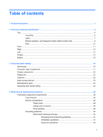
parts ...23 Sequential part number listing ...24 4 Removal and replacement procedures ...28 Preliminary replacement requirements 28 Tools required ...28 Service considerations ...28 Plastic parts ...28 Cables and connectors 29 Drive handling 29 Grounding guidelines ...30 Electrostatic discharge - HP ProBook 4545s | HP ProBook 4545s Notebook PC - Maintenance and Service Guide - Page 6
Component replacement procedures 33 Service tag ...33 Battery ...34 Bottom door ...35 Bottom parts location ...36 WLAN/Bluetooth combo card 36 Optical drive ...39 Hard drive ...42 Keyboard ...44 Memory modules ...47 Metal heat shield ...48 Fan ...50 Heat sink ...51 Processor ...53 Top cover ...55 - HP ProBook 4545s | HP ProBook 4545s Notebook PC - Maintenance and Service Guide - Page 7
86 6 Specifications ...88 Computer specifications ...88 39.6-cm (15.6-in), HD display specifications 89 Hard drive specifications ...90 Blu-ray BD-R/RE DVD±RW SuperMulti DL Drive specifications 91 DVD±RW and CD-RW SuperMulti DL Combo Drive specifications 92 Blu-ray Disc ROM with SuperMulti DVD - HP ProBook 4545s | HP ProBook 4545s Notebook PC - Maintenance and Service Guide - Page 8
viii - HP ProBook 4545s | HP ProBook 4545s Notebook PC - Maintenance and Service Guide - Page 9
Name HP ProBook 4545s Notebook PC AMD A8-4500M, 2.8-GHz Max/1.9-GHz Base, 4-MB L2 cache, quad-core, 35W Graphics: HD 7640G AMD A6-4400M, 3.20-GHz Max/2.7-GHz Base, 1-MB L2 cache, dual-core, 35W Graphics: HD 7520G AMD A4-4300M, 3.0-GHz Max/2.5-GHz Base, 1-MB L2 cache, dual-core, 35W Graphics: HD - HP ProBook 4545s | HP ProBook 4545s Notebook PC - Maintenance and Service Guide - Page 10
8192 MB (4096 × 2) (dual channel) ● 6144 MB (4096 + 2048) (dual channel) ● 4096 MB (2048 × 2) (dual channel) ● 4096 MB (4096 × 1) ● 2048 MB (2048 × 1) Supports 7-mm/9.5-mm/12.7-mm, and 2.5-in SATA hard drives with HP 3D DriveGuard Customer-accessible Supports the following drives: ● 750-GB, 7200-rpm - HP ProBook 4545s | HP ProBook 4545s Notebook PC - Maintenance and Service Guide - Page 11
802.11 b/g/n 1x1 WiFi adapter √ √ Integrated personal area network (WPAN) options by way of Bluetooth® √ √ module: Bluetooth 4.0 only supported by combo card √ √ External media 6-in-1 Digital Media Reader Slot. Supports SD,SDHC, SDXC, MMC, MMC+ and √ √ card Memory Stick Ports Audio - HP ProBook 4545s | HP ProBook 4545s Notebook PC - Maintenance and Service Guide - Page 12
Office 2010 Professional (Japan only) Restore Media: Windows 7 Professional 64 Windows 7 Home Basic 64 Windows 7 Home Premium 64 DRDVD Windows 7 Web-only support: Windows XP Professional Windows 7 Home Basic 32 Windows 7 Home Premium 32 Windows 7 Professional 32 Certified: Microsoft WHQL UMA - HP ProBook 4545s | HP ProBook 4545s Notebook PC - Maintenance and Service Guide - Page 13
Category Serviceability Description End-user replaceable parts: AC adapter Battery (system) Hard drive Optical drive Memory module WLAN module Keyboard UMA Discrete √ √ √ √ √ √ √ √ √ √ √ √ √ √ 5 - HP ProBook 4545s | HP ProBook 4545s Notebook PC - Maintenance and Service Guide - Page 14
(1) (2) TouchPad on/off button TouchPad zone (3) Left TouchPad button (4) Right TouchPad button Description Turns the TouchPad on and off. Moves the pointer and selects or activates items on the screen. Functions like the left button on an external mouse. Functions like the right button on an - HP ProBook 4545s | HP ProBook 4545s Notebook PC - Maintenance and Service Guide - Page 15
on. ● Off: The computer is off, in Suspended state, or in Hibernation. ● White: An integrated wireless device, such as a wireless local area network (WLAN) device and/or a Bluetooth® device, is on. ● Amber: All wireless devices are off. ● Amber: The TouchPad is off. ● Off: The TouchPad is on. Top 7 - HP ProBook 4545s | HP ProBook 4545s Notebook PC - Maintenance and Service Guide - Page 16
5 seconds to turn off the computer. CAUTION: Emergency shutdown procedures result in the loss of unsaved information. To learn more about your power settings: ● Select Start>Control Panel>System and Security>Power Options. ● For more information, see the HP Notebook Reference Guide. Produce sound - HP ProBook 4545s | HP ProBook 4545s Notebook PC - Maintenance and Service Guide - Page 17
Component (4) Wireless button (5) Fingerprint reader (select models only) Description Turns the wireless feature on or off but does not establish a wireless connection. Allows a fingerprint logon to the operating system, instead of a password logon. Top 9 - HP ProBook 4545s | HP ProBook 4545s Notebook PC - Maintenance and Service Guide - Page 18
the num lk key, the esc key, or other keys. Displays the Windows Start menu. Execute frequently used system functions when pressed in combination with the fn function that is active when the computer is turned off is reinstated when the computer is turned back on. Can be used like an external - HP ProBook 4545s | HP ProBook 4545s Notebook PC - Maintenance and Service Guide - Page 19
Description ● Blinking white: The hard drive or optical drive is being accessed. ● Amber: HP 3D DriveGuard has temporarily parked the hard drive. Supports the following digital card formats: ● Memory Stick PRO ● Memory Stick PRO Duo (needs an adapter) ● MultiMediaCard (MMC) ● MultiMediaCardPlus (MMC - HP ProBook 4545s | HP ProBook 4545s Notebook PC - Maintenance and Service Guide - Page 20
2.0 port Connect an optional USB device. For more information about USB devices, see the HP Notebook Reference Guide Optical drive (select models only) Reads an optical disc. NOTE: On select models, the optical drive also writes to an optical disc. Optical drive light (select models only) Lights - HP ProBook 4545s | HP ProBook 4545s Notebook PC - Maintenance and Service Guide - Page 21
VGA monitor or projector. Connects a network cable. Connects an optional video or audio device, such as a high-definition television, or any compatible digital or audio component. Connect an optional USB device. For more information about USB devices, see the HP Notebook Reference Guide. Left 13 - HP ProBook 4545s | HP ProBook 4545s Notebook PC - Maintenance and Service Guide - Page 22
Send and receive wireless signals to communicate with wireless local area networks (WLAN). (2) Internal microphone(s) (1 or 2 depending on To use the webcam, select Start>All Programs>ArcSoft TotalMedia Suite>WebCam Companion. (5) Internal display switch Turns off the display or initiates - HP ProBook 4545s | HP ProBook 4545s Notebook PC - Maintenance and Service Guide - Page 23
has been removed from the battery bay, releases the service door from the computer by sliding the release latches a second time. Holds the battery. Protects the hard drive bay, the wireless LAN (WLAN) module slot, and the memory module slots. CAUTION: To prevent an unresponsive system, replace the - HP ProBook 4545s | HP ProBook 4545s Notebook PC - Maintenance and Service Guide - Page 24
product. ● Part number/Product number (p/n) (3). This number provides specific information about the product's hardware components. The part number helps a service technician to determine what components and parts are needed. ● Warranty period (4). This number describes the duration (in years) of - HP ProBook 4545s | HP ProBook 4545s Notebook PC - Maintenance and Service Guide - Page 25
Computer major components Item (1) Description Display panel 39.6-cm (15.6-inch) HD, Anti-glare, with webcam Spare part number 683597-001 Computer major components 17 - HP ProBook 4545s | HP ProBook 4545s Notebook PC - Maintenance and Service Guide - Page 26
UMA graphics Fingerprint reader module (includes cable) Optical drive extender board Metal heat shield Hard drive extender board Base enclosure Battery, Li-ion 9-cell (93 WHr, 2.8 Ah) 6-cell (47 WHr, 2.2 Ah) WLAN module Atheros 9485GN 802.11b/g/n 1x1 WiFi and 3012 Bluetooth 4.0 Combo Adapter Atheros - HP ProBook 4545s | HP ProBook 4545s Notebook PC - Maintenance and Service Guide - Page 27
thermal material) AMD A6-4400M (3.0-GHz/2.6-GHz, 4-MB L2 cache) 683047-001 AMD A8-4500M (3.0-GHz/2.1-GHz, 2-MB L2 cache) 683048-001 Heat sink (includes replacement thermal material - thermal grease for CPU and thermal pad for VGA) For use in models with discrete graphics 683602-001 For - HP ProBook 4545s | HP ProBook 4545s Notebook PC - Maintenance and Service Guide - Page 28
Display components Item (1) (2) (3) (4) Description Display hinge covers (part of Display hinge kit 683480-001) Display bezel For use with models with a webcam For use with models without a webcam Webcam module Microphone module (not illustrated) Display hinges (includes left and right hinges, - HP ProBook 4545s | HP ProBook 4545s Notebook PC - Maintenance and Service Guide - Page 29
Plastics Kit Item (1) (2) Description Plastics Kit Optical drive protective insert Secure Digital card protective insert Spare part number 683501-001 Plastics Kit 21 - HP ProBook 4545s | HP ProBook 4545s Notebook PC - Maintenance and Service Guide - Page 30
Cable Kit Item Description Cable Kit (1) Battery cable (2) DC-in cable (3) Audio cable (4) USB module with cable 22 Chapter 3 Illustrated parts catalog Spare part number 683477-001 - HP ProBook 4545s | HP ProBook 4545s Notebook PC - Maintenance and Service Guide - Page 31
mm) Hard Drive Hardware Kit (includes hard drive bracket, mylar insulator, and screws) Miscellaneous parts Description AC adapters 65-W AC adapter 90-W AC adapter Power rubbers) Screw Kit (includes 15 ea all screws) HP keyed cable lock Mouse, optical, 2-button HP optical travel mouse Spare part - HP ProBook 4545s | HP ProBook 4545s Notebook PC - Maintenance and Service Guide - Page 32
-D01 A Power cord for use in Argentina 591699-001 A Notebook combination lock 592923-001 A Professional slim, top load case 609939-001 A 65-W AC adapter 609940-001 A 90-W AC adapter 612757-001 A Nylon case 621565-001 A 2-GB memory module (PC3-10600, 1333-MHz, DDR3) 621569-001 A 4-GB - HP ProBook 4545s | HP ProBook 4545s Notebook PC - Maintenance and Service Guide - Page 33
802.11b/g/n 1x1 WIFi and 20702 Bluetooth 4.0 Combo Adapter 669300-001 A 640-GB, 5400 rpm (2.5-in) hard drive 670691-001 A Ralink WLAN Ralink Ripple3 RT5390F 802.11b/g/n 1x1 PCIe HMC 675794-001 A Atheros AR9485 802.11b/g/n WiFi Adapter HMC 683047-001 N AMD processor A6-4400M (3.0-GHz/2.6-GHz - HP ProBook 4545s | HP ProBook 4545s Notebook PC - Maintenance and Service Guide - Page 34
683491-FP1 A Keyboard with TouchPad with TouchPad for use in Africa-French 683498-001 N ODD extender board 683499-001 N Blu-ray BD-R/RE DVD±RW SuperMulti DL Drive 683500-001 N DVD ROM Drive SuperMulti 683501-001 N Plastics Kit, includes bottom door, Secure digital card protective insert - HP ProBook 4545s | HP ProBook 4545s Notebook PC - Maintenance and Service Guide - Page 35
board for use in models with UMA graphics 683601-001 N RTC battery 683602-001 N Heat sink for use in models with discrete graphics 683603-001 N Heat sink for use in models with UMA graphics 689696-001 N Metal heat shield for 39.6-cm (15.6-in) models 690978-001 A Bottom door Sequential - HP ProBook 4545s | HP ProBook 4545s Notebook PC - Maintenance and Service Guide - Page 36
You will need the following tools to complete the removal and replacement procedures: ● Flat-bladed screwdriver ● Phillips P0 and P1 screwdrivers ● Torx T8 screwdriver Service considerations The following sections include some of the considerations that you must keep in mind during disassembly and - HP ProBook 4545s | HP ProBook 4545s Notebook PC - Maintenance and Service Guide - Page 37
care. To prevent damage to the computer, damage to a drive, or loss of information, observe these precautions: Before removing or inserting a hard drive, shut down the computer. If you are unsure whether the computer is off or in Hibernation, turn the computer on, and then shut it down through the - HP ProBook 4545s | HP ProBook 4545s Notebook PC - Maintenance and Service Guide - Page 38
degree of sensitivity. Networks built into many integrated 15,000 V 12,000 V 5,000 V 6,000 V 800 V 2,000 V 700 V 11,500 V 4,000 V 14,500 V 5,000 V 26,500 V 20,000 V 21,000 V 11,000 V 55% 7,500 V 3,000 V 400 V 400 V 2,000 V 3,500 V 7,000 V 5,000 V 30 Chapter 4 Removal and replacement - HP ProBook 4545s | HP ProBook 4545s Notebook PC - Maintenance and Service Guide - Page 39
components, parts, and assemblies by the case or PCM laminate. Handle these items only at static-free workstations. ● Avoid contact with pins, leads, or circuitry. ● Turn off power and input signals before inserting or removing connectors or test equipment. Preliminary replacement requirements 31 - HP ProBook 4545s | HP ProBook 4545s Notebook PC - Maintenance and Service Guide - Page 40
straps (heel, toe, or boot straps) can be used at standing workstations and are compatible with most types of shoes or boots. On conductive floors or dissipative tables or floor mats with hard ties to the ground ● Field service kits ● Static awareness labels ● 4 Removal and replacement procedures - HP ProBook 4545s | HP ProBook 4545s Notebook PC - Maintenance and Service Guide - Page 41
as many as 95 screws and screw locks, in 15 different sizes, that must be removed, replaced, or loosened when servicing the computer. Make special note of each screw and screw lock size and location during removal and replacement. Service tag When ordering parts or requesting information, provide - HP ProBook 4545s | HP ProBook 4545s Notebook PC - Maintenance and Service Guide - Page 42
from the AC outlet, and then unplugging the AC adapter from the computer. Remove the battery: 1. Position the computer upside-down on a flat surface with the battery bay away from you. 2. Slide the battery release latches (1) to release the battery. 3. Pivot the battery (2) upward to remove it from - HP ProBook 4545s | HP ProBook 4545s Notebook PC - Maintenance and Service Guide - Page 43
the computer. 3. Disconnect the power from the computer by first unplugging the power cord from the AC outlet, and then unplugging the AC adapter from the computer. 4. Remove the battery (see Battery on page 34). Remove the bottom door: 1. Position the computer upside-down on a flat surface with the - HP ProBook 4545s | HP ProBook 4545s Notebook PC - Maintenance and Service Guide - Page 44
Bottom parts location Some customer replaceable parts are accessible after removing the bottom door. Item 1 2 3 Description Memory module Hard drive WLAN module WLAN/Bluetooth combo card The computer uses a card that provides both WLAN and Bluetooth functionality. CAUTION: The WLAN module and the - HP ProBook 4545s | HP ProBook 4545s Notebook PC - Maintenance and Service Guide - Page 45
Yemen, Zaire, Zambia, and Zimbabwe Broadcom 4313GN 802.11b/gn 1x1 WiFi and 20702 Bluetooth 4.0 Combo Adapter Rallink WLAN Ralink Ripple3 RT5390F 802.11b/g/n 1x1 PCIe HMC 670691-001 Rallink Zimbabwe Rallink WLAN Ralink Ripple3 RT5390F 802.11b/g/n 1x1 PCIe HMC Component replacement procedures 37 - HP ProBook 4545s | HP ProBook 4545s Notebook PC - Maintenance and Service Guide - Page 46
from the computer by first unplugging the power cord from the AC outlet, and then unplugging the AC adapter from the computer. 4. Remove the battery (see Battery on page 34). 5. Remove the bottom door (see Bottom door on page 35). Remove the WLAN module: 1. Position the computer upside-down with the - HP ProBook 4545s | HP ProBook 4545s Notebook PC - Maintenance and Service Guide - Page 47
5. Remove the WLAN module (3) drive bezel and a bracket with mounting screws. Description Blu-ray BD-R/RE DVD±RW SuperMulti DL Drive (includes bracket and screws) DVD±RW and CD-RW SuperMulti DL Combo Drive (includes bracket and screws) Spare part number 683499-001 683500-001 Component replacement - HP ProBook 4545s | HP ProBook 4545s Notebook PC - Maintenance and Service Guide - Page 48
the computer by first unplugging the power cord from the AC outlet, and then unplugging the AC adapter from the computer. 4. Remove the battery (see Battery on page 34). 5. Remove the bottom door (see Bottom door on page 35). Remove the optical drive: 1. Position the computer upside-down with the - HP ProBook 4545s | HP ProBook 4545s Notebook PC - Maintenance and Service Guide - Page 49
5. If it is necessary to replace the optical drive bracket, position the optical drive with the rear toward you. 6. Remove the two Phillips PM2.0×3.0 screws (1) that secure the optical drive bracket to the optical drive. 7. Remove the optical drive bracket (2). Reverse this procedure to install an - HP ProBook 4545s | HP ProBook 4545s Notebook PC - Maintenance and Service Guide - Page 50
the computer by first unplugging the power cord from the AC outlet, and then unplugging the AC adapter from the computer. 4. Remove the battery (see Battery on page 34). 5. Remove the bottom door (see Bottom door on page 35). Remove the hard drive: 1. Position the computer upside-down with the front - HP ProBook 4545s | HP ProBook 4545s Notebook PC - Maintenance and Service Guide - Page 51
connector and lift it from the hard drive bay. . 5. If it is necessary to replace the hard drive bracket, unwrap the mylar cover (1) that surrounds the drive. 6. Remove the two Phillips PM3.0×3.0 hard drive bracket screws (2) from each side of the hard drive (4 total screws). 7. Lift the mounting - HP ProBook 4545s | HP ProBook 4545s Notebook PC - Maintenance and Service Guide - Page 52
the power cord from the AC outlet, and then unplugging the AC adapter from the computer. 4. Remove the battery (see Battery on page 34). 5. Remove the bottom door (see Bottom door on page 35). 6. Remove the Optical drive (see Optical drive on page 39). Remove the keyboard: 1. Position the computer - HP ProBook 4545s | HP ProBook 4545s Notebook PC - Maintenance and Service Guide - Page 53
2. Remove the three Phillips PM2.5×6.0 screws that secure the keyboard to the computer. 3. Position the computer on its side with the bottom facing you and the computer open. 4. Insert a screwdriver or similar tool in the Optical drive compartment and push to disengage the keyboard. 5. Position the - HP ProBook 4545s | HP ProBook 4545s Notebook PC - Maintenance and Service Guide - Page 54
top (2) and pull it out of the top cover (3). 8. Rotate the keyboard (1) to access the cable connector. 9. Release the cable locking device (2) and remove the cable (3). The keyboard may now be set aside. Reverse this procedure to install the keyboard. 46 Chapter 4 Removal and replacement procedures - HP ProBook 4545s | HP ProBook 4545s Notebook PC - Maintenance and Service Guide - Page 55
adding memory modules Before adding new memory, make sure you update the computer to the latest BIOS. CAUTION: Failure to update the computer to the latest BIOS prior to installing new memory may result in various system problems. To update BIOS: 1. Navigate to www.hp.com. 2. Click Support & Drivers - HP ProBook 4545s | HP ProBook 4545s Notebook PC - Maintenance and Service Guide - Page 56
the computer by first unplugging the power cord from the AC outlet, and then unplugging the AC adapter from the computer. 4. Remove the battery (see Battery on page 34). 5. Remove the bottom door (see Bottom door on page 35). Remove the metal heat shield: 1. Position the computer upside-down with - HP ProBook 4545s | HP ProBook 4545s Notebook PC - Maintenance and Service Guide - Page 57
3. Slide the shield to the left (2), then rotate the shield up (3) and remove it (4) from the base enclosure . Reverse this procedure to install the metal heat shield. Component replacement procedures 49 - HP ProBook 4545s | HP ProBook 4545s Notebook PC - Maintenance and Service Guide - Page 58
the AC outlet, and then unplugging the AC adapter from the computer. 4. Remove the battery (see Battery on page 34). 5. Remove controlled by a temperature sensor and is designed to turn on automatically when high temperature conditions exist. These conditions are 50 Chapter 4 Removal and replacement - HP ProBook 4545s | HP ProBook 4545s Notebook PC - Maintenance and Service Guide - Page 59
3. Disconnect the power from the computer by first unplugging the power cord from the AC outlet, and then unplugging the AC adapter from the computer. 4. Remove the battery (see Battery on page 34). 5. Remove the following components: a. Bottom door (see Bottom door on page 35). b. Metal heat shield - HP ProBook 4545s | HP ProBook 4545s Notebook PC - Maintenance and Service Guide - Page 60
left (3) to remove it from the system board. Remove the UMA heat sink. 1. Position the computer upside down with battery bay away from user. 2. To remove the discrete heat sink sink components(2) and (4) each time you remove the heat sink. All heat sink and processor spare part kits include thermal - HP ProBook 4545s | HP ProBook 4545s Notebook PC - Maintenance and Service Guide - Page 61
NOTE: All processor spare part kits include replacement thermal material. Description AMD A6-4400M APU (3.0-GHz/2.6-GHz, 4-MB L2 cache) AMD A8-4500M APU (3.0-GHz/2.1-GHz, 4-MB L2 cache) Spare part number 683047-001 683048-001 Before removing the processor, follow these steps: 1. Shut down - HP ProBook 4545s | HP ProBook 4545s Notebook PC - Maintenance and Service Guide - Page 62
from the AC outlet, and then unplugging the AC adapter from the computer. 4. Remove the battery (see Battery on page 34). 5. Remove the following to turn the processor locking screw (1) one-half turn counterclockwise until you hear a click. 3. Lift the processor (2) straight up and remove it. - HP ProBook 4545s | HP ProBook 4545s Notebook PC - Maintenance and Service Guide - Page 63
unplugging the AC adapter from the computer. 4. Remove the battery (see Battery on page 34). 5. Remove the following components: a. Bottom door (see Bottom door on page 35). b. Optical drive (see Optical drive on page 39). c. Hard drive (see Hard drive on page 42). d. Keyboard (see Keyboard on page - HP ProBook 4545s | HP ProBook 4545s Notebook PC - Maintenance and Service Guide - Page 64
2. Remove the following covers and screws that secure the top cover to the computer: (1) 4 rubber screw covers (2) 11 Torx T8M2.5×6.0 screws 56 Chapter 4 Removal and replacement procedures - HP ProBook 4545s | HP ProBook 4545s Notebook PC - Maintenance and Service Guide - Page 65
the top cover to the computer: (1) Two Phillips PM2.0×4.0 screws from the optical drive bay (2) Three Phillips PM2×2 broadhead screws from the battery bay 4. Turn the computer upright and open it as far as possible. 5. Remove the 2 Torx T8M2.5×6.0 screws that secure the top cover to the computer - HP ProBook 4545s | HP ProBook 4545s Notebook PC - Maintenance and Service Guide - Page 66
● Lift the connector latch and disconnect the function/power board cable (1) ● Disconnect the speaker cable (2) ● Lift the connector latch and disconnect the fingerprint reader board cable (3) 7. Position the computer on its side with the display open. 58 Chapter 4 Removal and replacement procedures - HP ProBook 4545s | HP ProBook 4545s Notebook PC - Maintenance and Service Guide - Page 67
8. Insert a screwdriver through the holes in the battery bay and press to disengage the top cover from the computer. 9. Position the computer upright with the front toward you. Component replacement procedures 59 - HP ProBook 4545s | HP ProBook 4545s Notebook PC - Maintenance and Service Guide - Page 68
(3), and then lift the bottom of the top cover (4) to remove it enough to access the card reader cable underneath. 11. Lift the front of the top cover connector underneath. 12. Lift the connector latch (1), disconnect the card reader cable (2), and then lift the top cover from the computer (3). - HP ProBook 4545s | HP ProBook 4545s Notebook PC - Maintenance and Service Guide - Page 69
unplugging the AC adapter from the computer. 4. Remove the battery (see Battery on page 34). 5. Remove the following components: a. Bottom door (see Bottom door on page 35). b. Optical drive (see Optical drive on page 39). c. Hard drive (see Hard drive on page 42). d. Keyboard (see Keyboard on page - HP ProBook 4545s | HP ProBook 4545s Notebook PC - Maintenance and Service Guide - Page 70
power cord from the AC outlet, and then unplugging the AC adapter from the computer. 4. Remove the battery (see Battery on page 34). 5. Remove the following components: a. Bottom door (see Bottom door on page 35). b. Optical drive (see Optical drive on page 39). c. Keyboard (see Keyboard on page 44 - HP ProBook 4545s | HP ProBook 4545s Notebook PC - Maintenance and Service Guide - Page 71
power cord from the AC outlet, and then unplugging the AC adapter from the computer. 4. Remove the battery (see Battery on page 34). 5. Remove the following components: a. Bottom door (see Bottom door on page 35). b. Optical drive (see Optical drive on page 39). Component replacement procedures 63 - HP ProBook 4545s | HP ProBook 4545s Notebook PC - Maintenance and Service Guide - Page 72
Before removing the fingerprint board, follow these steps: 1. Shut down the computer. If you are unsure whether the computer is off or in Hibernation, turn the the power cord from the AC outlet, and then unplugging the AC adapter from the computer. 64 Chapter 4 Removal and replacement procedures - HP ProBook 4545s | HP ProBook 4545s Notebook PC - Maintenance and Service Guide - Page 73
door (see Bottom door on page 35). b. Optical drive (see Optical drive on page 39). c. Keyboard (see Keyboard on page 44). d. Metal heat shield (see Metal heat shield on page 48). e. Top cover (see Top cover on page 55). Remove the fingerprint board: 1. Position the top cover upside-down with the - HP ProBook 4545s | HP ProBook 4545s Notebook PC - Maintenance and Service Guide - Page 74
the AC adapter from the computer. 4. Remove the battery (see Battery on page 34). 5. Remove the following components: a. Bottom door (see Bottom door on page 35). b. Optical drive (see Optical drive on page 39). c. Metal heat shield (see Metal heat shield on page 48). d. Keyboard (see Keyboard on - HP ProBook 4545s | HP ProBook 4545s Notebook PC - Maintenance and Service Guide - Page 75
AC adapter from the computer. 4. Remove the battery (see Battery on page 34). 5. Remove the following components: a. Bottom door (see Bottom door on page 35). b. Hard drive (see Hard drive on page 42). c. Optical drive (see Optical drive on page 39). d. WLAN/Bluetooth combo card (see WLAN/Bluetooth - HP ProBook 4545s | HP ProBook 4545s Notebook PC - Maintenance and Service Guide - Page 76
(see Top cover on page 55). When replacing the system board, be sure to remove the following components from the defective system board and install on the replacement system board: ● Memory module (see Memory modules on page 47). ● WLAN card(see WLAN/Bluetooth combo card on page 36). ● Fan (see Fan - HP ProBook 4545s | HP ProBook 4545s Notebook PC - Maintenance and Service Guide - Page 77
screws (2) that secure the battery cable connector to the base enclosure and remove the connector (3). 7. Remove the four screws (1) that secure the system board and the drive extenders to the base enclosure. 8. Lift the system board (2) up on its right end and remove it from the computer . Reverse - HP ProBook 4545s | HP ProBook 4545s Notebook PC - Maintenance and Service Guide - Page 78
cord from the AC outlet, and then unplugging the AC adapter from the computer. 4. Remove the battery (see Battery on page 34). 5. Remove the following components: a. Bottom door (see Bottom door on page 35). b. Hard drive (see Hard drive on page 42). c. Optical drive (see Optical drive on page 39 - HP ProBook 4545s | HP ProBook 4545s Notebook PC - Maintenance and Service Guide - Page 79
cord from the AC outlet, and then unplugging the AC adapter from the computer. 4. Remove the battery (see Battery on page 34). 5. Remove the following components: a. Bottom door (see Bottom door on page 35). b. Hard drive (see Hard drive on page 42). c. Optical drive (see Optical drive on page 39 - HP ProBook 4545s | HP ProBook 4545s Notebook PC - Maintenance and Service Guide - Page 80
Remove the power cable: 1. Position the system upright with the front toward you. 2. Disconnect the cable (1) from the bottom of the system board . 3. Lift the power cable assembly (2) from the computer . Reverse this procedure to install the power cable. 72 Chapter 4 Removal and replacement - HP ProBook 4545s | HP ProBook 4545s Notebook PC - Maintenance and Service Guide - Page 81
cord from the AC outlet, and then unplugging the AC adapter from the computer. 4. Remove the battery (see Battery on page 34). 5. Remove the following components: a. Bottom door (see Bottom door on page 35). b. Optical drive (see Optical drive on page 39). c. Hard drive (see Hard drive on page 42 - HP ProBook 4545s | HP ProBook 4545s Notebook PC - Maintenance and Service Guide - Page 82
straight out of the system board. Reverse this procedure to install the hard drive extender. Remove the optical drive extender: 1. Position the system board with the drive extenders to your right. 2. Pull the optical drive extender straight out of the system board. Reverse this procedure to install - HP ProBook 4545s | HP ProBook 4545s Notebook PC - Maintenance and Service Guide - Page 83
the AC adapter from the computer. 4. Remove the battery (see Battery on page 34). 5. Remove the following components: a. Bottom door (see Bottom door on page 35). b. Optical drive (see Optical drive on page 39). c. WLAN module (see WLAN/Bluetooth combo card on page 36). d. Keyboard (see Keyboard on - HP ProBook 4545s | HP ProBook 4545s Notebook PC - Maintenance and Service Guide - Page 84
3. Remove the WLAN cable from the cable raceway (1) and from the cable clips (2). 4. Remove the display cable (1) from the raceway and release them from the cable clips (2). 5. Remove two Torx T8M2.5×7.0 screws from each of the two hinges (1). 76 Chapter 4 Removal and replacement procedures - HP ProBook 4545s | HP ProBook 4545s Notebook PC - Maintenance and Service Guide - Page 85
6. Lift the display from the computer (2). 7. If you need to remove the hinge covers from the display hinges, pull the hinges straight up and off the display to remove them. Display hinge covers are spared with the Display hinge kit, spare part number 683480-001. Component replacement procedures 77 - HP ProBook 4545s | HP ProBook 4545s Notebook PC - Maintenance and Service Guide - Page 86
8. To replace the display bezel, remove the two rubber screw covers (1) and the two Torx T8M2.5×6.0 sides (4), and then the bottom (5) of the bezel until it disengages from the display enclosure. Remove the display bezel. The bezel is available using the following spare part numbers: 683596-001: - HP ProBook 4545s | HP ProBook 4545s Notebook PC - Maintenance and Service Guide - Page 87
and is available using spare part number 647675-001. 11. If it is necessary to replace the display hinges, remove the Phillips PM2.5×3.0 screws (1) that secure each display hinge to the display panel. 12. Remove the display hinges (2). Display hinges are available using spare part number 646279-001 - HP ProBook 4545s | HP ProBook 4545s Notebook PC - Maintenance and Service Guide - Page 88
Reverse the process to install the display hinges. 80 Chapter 4 Removal and replacement procedures - HP ProBook 4545s | HP ProBook 4545s Notebook PC - Maintenance and Service Guide - Page 89
can prevent the computer from operating properly. Starting Computer Setup NOTE: An external keyboard or mouse connected to a USB port can be used with Computer Setup only if USB legacy support is enabled. To start Computer Setup, follow these steps: 1. Turn on or restart the computer, and then - HP ProBook 4545s | HP ProBook 4545s Notebook PC - Maintenance and Service Guide - Page 90
the on-screen instructions. - or - Use the tab key and the arrow keys to select File > Save Changes and Exit, and then press enter. Your changes go into effect when the computer restarts. Restoring factory settings in Computer Setup NOTE: Restoring defaults will not change the hard drive mode. To - HP ProBook 4545s | HP ProBook 4545s Notebook PC - Maintenance and Service Guide - Page 91
then follow the on-screen instructions to update the BIOS. NOTE: Some download packages contain a file named Readme.txt, which contains information regarding installing and troubleshooting the file. BIOS management using system diagnostics 1. Download the SoftPaq from the HP website. NOTE: Verify - HP ProBook 4545s | HP ProBook 4545s Notebook PC - Maintenance and Service Guide - Page 92
on-screen instructions to download your selection to the hard drive. Make a note of the path to the location on your hard drive where the BIOS update is downloaded. You will need to access this path when you are ready to install the update. NOTE: If you connect your computer to a network, consult - HP ProBook 4545s | HP ProBook 4545s Notebook PC - Maintenance and Service Guide - Page 93
BIOS installation procedures vary. Follow any instructions that are displayed on the screen after the download is complete. If no instructions are displayed, follow these steps: 1. Open Windows Explorer by selecting Start > Computer. 2. Double-click your hard drive designation. The hard drive - HP ProBook 4545s | HP ProBook 4545s Notebook PC - Maintenance and Service Guide - Page 94
, and system BIOS. Security menu Select Administrator password Power-on password To do this Control access to Setup Utility. Control access to your computer. Diagnostics menu Select Primary Hard Disk Self Test Memory Test To do this Run a quick or comprehensive self-test on the hard drive. Run - HP ProBook 4545s | HP ProBook 4545s Notebook PC - Maintenance and Service Guide - Page 95
of the battery and calibrates the battery if necessary. If the battery fails the test, contact support to report the issue and purchase a replacement battery. You can view system information and error logs in the Advanced System Diagnostics window. To start Advanced System Diagnostics: 1. Turn on or - HP ProBook 4545s | HP ProBook 4545s Notebook PC - Maintenance and Service Guide - Page 96
3.6 cm 1.1 to 1.4 in Weight (equipped with optical drive, 1 DIMM, hard drive, optical drive, WLAN module, 6 cell battery) 2.5 kg 5.5 lbs Input power Operating voltage 19.0 Maximum altitude (unpressurized) Operating -15 m to 3,048 m -50 ft to 10,000 ft Nonoperating -15 m to 12,192 m - - HP ProBook 4545s | HP ProBook 4545s Notebook PC - Maintenance and Service Guide - Page 97
39.6-cm (15.6-in), HD display specifications Active diagonal size Resolution Active area ) - Anti-glare 500:1 - BrightView 8 ms 200 nits (typical) SVA LED 1.4 (typ), 1.6 (max) 12,000 hours (0.313, 0.329) +/- 0.02 +/- 0.03 60% (typical) U.S. 15.6-in 39.6-cm (15.6-in), HD display specifications 89 - HP ProBook 4545s | HP ProBook 4545s Notebook PC - Maintenance and Service Guide - Page 98
to 55°C (41°F to 131°F) *1 GB = 1 billion bytes when referring to hard drive storage capacity. Actual accessible capacity is less. Actual drive specifications may differ slightly. NOTE: Certain restrictions and exclusions apply. Contact technical support for details. 90 Chapter 6 Specifications - HP ProBook 4545s | HP ProBook 4545s Notebook PC - Maintenance and Service Guide - Page 99
DL Drive specifications Applicable disc Access time Random Maximum Media Capacity (read) Maximum Media Capacity (write) Data transfer rate 24X CD-ROM 8X DVD 2X BD-ROM 16X CD-R 16X CD-RW 8X DVD+R 6X DVD+RW 8X DVD-R 6X DVD-RW 4X DVD+R Dual Layer 4X DVD-R Dual Layer 5X DVD-RAM 2X - HP ProBook 4545s | HP ProBook 4545s Notebook PC - Maintenance and Service Guide - Page 100
±RW and CD-RW SuperMulti DL Combo Drive specifications Applicable disc Center hole diameter Disc DVD-10, DVD-18), DVDR, DVD-RW, DVD+R, DVD+RW, DVD-RAM CD-R and CD-RW DVD+R, DVD+RW, DVD-R, DVDRW, DVD-RAM 1.5 cm (0.59 in) 12 cm (4.72 in) 8 cm (3.15 in) 1.2 mm (0.047 in) 0.74 µm CD < 175 ms < 285 - HP ProBook 4545s | HP ProBook 4545s Notebook PC - Maintenance and Service Guide - Page 101
Drive Applicable disc Access time Random Cache buffer Data transfer rate 24X CD-ROM 8X DVD 24X CD-R 16X CD-RW 8X DVD+R 4X DVD+RW 8X DVD-R 4X DVD-RW 2.4X DVD+R(9) 5X DVD-RAM -RW, DVD+R, DVD+RW, DVD-RAM, HDROM (Single Layer), HD-ROM (Dual Layer), HD DVD-R, HD DVD-R for Dual Layer, HD DVD-RW CD-R and - HP ProBook 4545s | HP ProBook 4545s Notebook PC - Maintenance and Service Guide - Page 102
DVD-ROM Drive specifications Applicable disc Center hole diameter Disc diameter 1 and Form 2), CD-R, CD-RW, Photo CD (single and multisession), CD-Bridge 1.5 cm (0.59 in) 12 cm (4.72 in) 8 cm (3.15 in) 1.2 mm (0.047 in) 0.74 µm CD < 100 ms < 175 ms Line-out, 0.7 Vrms 512 KB DVD < 125 ms < 225 - HP ProBook 4545s | HP ProBook 4545s Notebook PC - Maintenance and Service Guide - Page 103
7 includes the User Account Control feature to improve the security of your computer. You may be prompted for your permission or password for tasks such as installing software, running utilities, or changing Windows settings. Refer to Windows Help and Support for more information. After you open - HP ProBook 4545s | HP ProBook 4545s Notebook PC - Maintenance and Service Guide - Page 104
recovery tools NOTE: For detailed instructions, perform a search for these topics in Help and Support. In case of system instability, HP recommends that you print the recovery procedures and save them for later use. NOTE: Windows includes the User Account Control feature to improve the security of - HP ProBook 4545s | HP ProBook 4545s Notebook PC - Maintenance and Service Guide - Page 105
used to start up (boot) the computer and repair the operating system in case of system instability or failure. Your initial and subsequent backups allow you to restore your data and settings if a failure occurs. You can back up your information to an optional external hard drive, a network drive, or - HP ProBook 4545s | HP ProBook 4545s Notebook PC - Maintenance and Service Guide - Page 106
fix problems that might prevent Windows from starting correctly. ● f11 recovery tools: You can use the f11 recovery tools to recover your original hard drive image. The image includes the Windows operating system and software programs installed at the factory. NOTE: If you are unable to boot (start - HP ProBook 4545s | HP ProBook 4545s Notebook PC - Maintenance and Service Guide - Page 107
on-screen instructions. You can also order the DVD by calling technical support. For contact information, refer to the Worldwide Telephone Numbers booklet included with the computer. CAUTION: Using a Windows 7 operating system DVD completely erases hard drive contents and reformats the hard drive - HP ProBook 4545s | HP ProBook 4545s Notebook PC - Maintenance and Service Guide - Page 108
After the repair is completed: 1. Eject the Windows 7 operating system DVD, and then insert the Driver Recovery disc. 2. Install the Hardware Enabling Drivers first, and then install Recommended Applications. 100 Chapter 7 Backup and recovery - HP ProBook 4545s | HP ProBook 4545s Notebook PC - Maintenance and Service Guide - Page 109
agency responsible for evaluation in the country or region where the power cord set will be used. ● The power cord sets must have a minimum current capacity of 10 A and a nominal voltage rating of 125 or 250 V ac, as required by the power system of each country or region. ● The appliance coupler - HP ProBook 4545s | HP ProBook 4545s Notebook PC - Maintenance and Service Guide - Page 110
mark of the agency responsible for evaluation in the country or region where it will be used. 2. The flexible cord must be Type SVT/SJT-3 or must be a two-pole grounding type with a NEMA 5-15P (15 A, 125 V ac) or NEMA 6-15P (15 A, 250 V ac) configuration. CSA or C-UL mark. UL file number must be on - HP ProBook 4545s | HP ProBook 4545s Notebook PC - Maintenance and Service Guide - Page 111
the backlight. When you remove these components, handle them carefully. NOTE: Materials Disposal. This HP product contains mercury in the panel (2). NOTE: The procedures provided in this chapter are general disassembly instructions. Specific details, such as screw sizes, quantities, and locations, - HP ProBook 4545s | HP ProBook 4545s Notebook PC - Maintenance and Service Guide - Page 112
Perform the following steps to disassemble the display assembly: 1. Remove all screw covers (1) and screws (2) that secure the display bezel to the display assembly (2) of the display bezel until the bezel disengages from the display assembly. 3. Remove the display bezel (3). 104 Chapter 9 Recycling - HP ProBook 4545s | HP ProBook 4545s Notebook PC - Maintenance and Service Guide - Page 113
the display panel assembly (2) from the display enclosure. 7. Position the display panel assembly upside-down. 8. Remove all screws that secure the display panel frame to the display panel. 9. Use a sharp-edged tool to cut the tape (1) that secures the sides of - HP ProBook 4545s | HP ProBook 4545s Notebook PC - Maintenance and Service Guide - Page 114
secure the backlight cover to the display panel. 12. Lift the top edge of the backlight cover (2) and swing it outward. 13. Remove the backlight cover. 14. Position the display panel right-side up. 15. Remove the backlight cables (1) from the clip (2) in the display panel. 106 Chapter 9 Recycling - HP ProBook 4545s | HP ProBook 4545s Notebook PC - Maintenance and Service Guide - Page 115
damaging this component and causing exposure to the mercury. 17. Remove the backlight frame from the display panel. 18. Remove the backlight from the backlight frame. 19. Disconnect the display panel cable (1) from the LCD panel. 20. Remove the screws (2) that secure the LCD panel to the display - HP ProBook 4545s | HP ProBook 4545s Notebook PC - Maintenance and Service Guide - Page 116
22. Release the tape (4) that secures the LCD panel to the display rear panel. 23. Remove the LCD panel. 24. Recycle the LCD panel and backlight. 108 Chapter 9 Recycling - HP ProBook 4545s | HP ProBook 4545s Notebook PC - Maintenance and Service Guide - Page 117
cable connector removal 68 battery cover 15 BIOS determining version 84 downloading an update 84 updating 83 Blu-ray BD-R/RE DVD±RW SuperMulti DL Drive 91 spare part number 19, 39 Blu-ray Disc ROM with SuperMulti DVD±R/RW DL Drive spare part number 23 specifications 93 Bluetooth card spare part - HP ProBook 4545s | HP ProBook 4545s Notebook PC - Maintenance and Service Guide - Page 118
num lk 10 Windows Applications 10 Windows logo 10 L latches, battery and service door release 15 legacy support, USB 81 lights caps lock 7 hard drive 11 optical drive 12 power 7 webcam 14 wireless 7 M mass storage devices, spare part numbers 23 memory module product description 1 removal 47 spare - HP ProBook 4545s | HP ProBook 4545s Notebook PC - Maintenance and Service Guide - Page 119
99 removal/replacement preliminaries 28 procedures 33 restoring the hard drive 99 RTC battery removal 70 spare part number 18, 70 S Screw Kit, spare part number 23 Secure Digital card insert, illustrated 21 security cable slot, identifying 13 security, product description 3 service considerations
-
 1
1 -
 2
2 -
 3
3 -
 4
4 -
 5
5 -
 6
6 -
 7
7 -
8
-
9
-
10
-
11
-
12
-
13
-
14
-
15
-
16
-
17
-
18
-
19
-
20
-
21
-
22
-
23
-
24
-
25
-
26
-
27
-
28
-
29
-
30
-
31
-
32
-
33
-
34
-
35
-
36
-
37
-
38
-
39
-
40
-
41
-
42
-
43
-
44
-
45
-
46
-
47
-
48
-
49
-
50
-
51
-
52
-
53
-
54
-
55
-
56
-
57
-
58
-
59
-
60
-
61
-
62
-
63
-
64
-
65
-
66
-
67
-
68
-
69
-
70
-
71
-
72
-
73
-
74
-
75
-
76
-
77
-
78
-
79
-
80
-
81
-
82
-
83
-
84
-
85
-
86
-
87
-
88
-
89
-
90
-
91
-
92
-
93
-
94
-
95
-
96
-
97
-
98
-
99
-
100
-
101
-
102
-
103
-
104
-
105
-
106
-
107
-
108
-
109
-
110
-
111
-
112
-
113
-
114
-
115
-
116
-
117
-
118
-
119
 |
 |

HP ProBook 4545s Notebook PC
Maintenance and Service Guide