HP ProLiant 2500 Compaq ProLiant 2500 Family of Servers Maintenance and Servic - Page 38
System I/O and Processor Backplane Board, MSG034.EPS
 |
View all HP ProLiant 2500 manuals
Add to My Manuals
Save this manual to your list of manuals |
Page 38 highlights
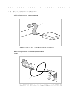
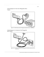
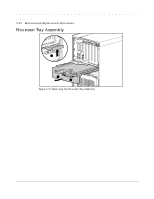
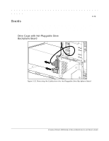
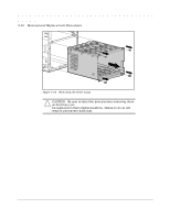
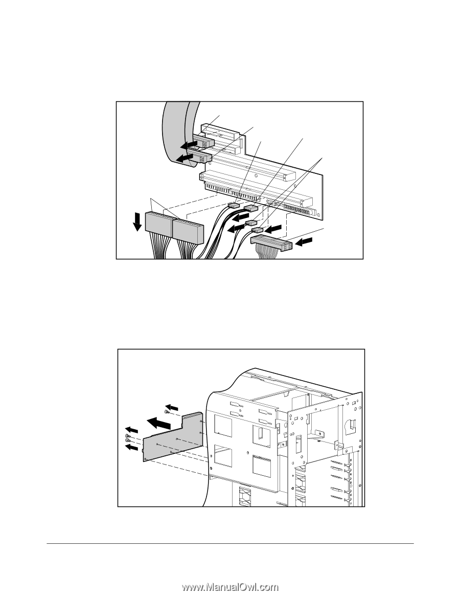
2-25 System I/O and Processor Backplane Board CD ROM Connector Floppy Connector SCSI LED Connector Power Supply Connector Fan Connectors Power Supply Connectors SCSI Connector MSG038.EPS Figure 2-24. Removing the System I/O and Processor Backplane Board 1. Remove the large access panel. 2. Remove the processor tray assembly. 3. Remove the system I/O board tray assembly (refer to "System I/O Board Tray Assembly" later in this document). 4. Disconnect the signal and power cables for the processor backplane board. MSG034.EPS Figure 2-25. Removing the System I/O and Processor Backplane Board Compaq ProLiant 2500 Family of Servers Maintenance and Service Guide
-
 1
1 -
2
-
3
-
4
-
5
-
6
-
7
-
8
-
9
-
10
-
11
-
12
-
13
-
14
-
15
-
16
-
17
-
18
-
19
-
20
-
21
-
22
-
23
-
24
-
25
-
26
-
27
-
28
-
29
-
30
-
31
-
32
-
 33
33 -
 34
34 -
 35
35 -
 36
36 -
 37
37 -
 38
38 -
 39
39 -
 40
40 -
 41
41 -
 42
42 -
 43
43 -
44
-
45
-
46
-
47
-
48
-
49
-
50
-
51
-
52
-
53
-
54
-
55
-
56
-
57
-
58
-
59
-
60
-
61
-
62
-
63
-
64
-
65
-
66
-
67
-
68
-
69
-
70
-
71
-
72
-
73
-
74
-
75
-
76
-
77
-
78
-
79
-
80
-
81
-
82
-
83
-
84
-
85
-
86
-
87
-
88
-
89
-
90
-
91
-
92
-
93
-
94
-
95
-
96
-
97
-
98
-
99
-
100
-
101
-
102
-
103
-
104
-
105
-
106
-
107
-
108
-
109
-
110
-
111
-
112
-
113
-
114
-
115
-
116
-
117
-
118
-
119
-
120
-
121
-
122
-
123
-
124
-
125
-
126
-
127
-
128
-
129
-
130
-
131
-
132
-
133
-
134
-
135
-
136
-
137
-
138
-
139
-
140
 |
 |
.
.
.
.
.
.
.
.
.
.
.
.
.
.
.
.
.
.
.
.
.
.
.
.
.
.
.
.
.
.
.
.
.
.
.
.
.
.
.
2-25
Compaq ProLiant 2500 Family of Servers Maintenance and Service Guide
System I/O and Processor Backplane Board
MSG038.EPS
CD ROM Connector
Floppy Connector
Power Supply
Connectors
SCSI LED
Connector
Fan
Connectors
SCSI
Connector
Power Supply
Connector
Figure 2-24.
Removing the System I/O and Processor Backplane Board
1.
Remove the large access panel.
2.
Remove the processor tray assembly.
3.
Remove the system I/O board tray assembly (refer to “System I/O Board Tray
Assembly” later in this document).
4.
Disconnect the signal and power cables for the processor backplane board.
MSG034.EPS
Figure 2-25.
Removing the System I/O and Processor Backplane Board