HP ProLiant 2500 Compaq ProLiant 2500 Family of Servers Maintenance and Servic - Page 41
System I/O Board Tray Assembly, MSG009.EPS
 |
View all HP ProLiant 2500 manuals
Add to My Manuals
Save this manual to your list of manuals |
Page 41 highlights
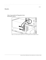
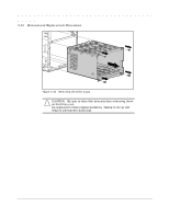
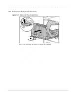
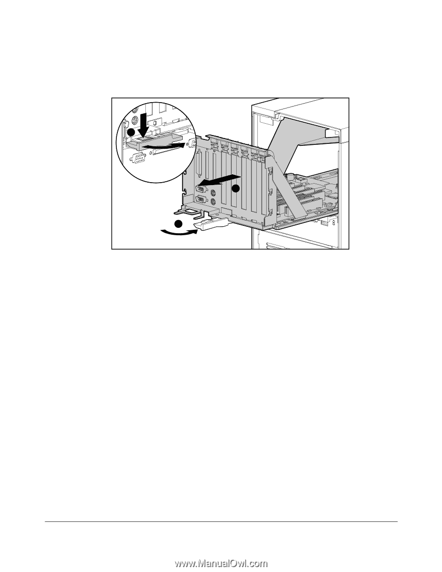
2-28 Removal and Replacement Procedures System I/O Board Tray Assembly A C B MSG009.EPS Figure 2-27. Removing the System I/O Board Tray Assembly 1. Remove the small access panel. 2. If installed, remove the security screw. 3. Disconnect all cables from expansion boards. 4. Press down the catch on the release lever [A] and swing the lever out [B] to unlock the system I/O board tray assembly. 5. Pull out the tray [C]. 6. Remove all expansion boards from the assembly. Reverse steps 1 to 6 to replace the system I/O board tray assembly.
-
 1
1 -
2
-
3
-
4
-
5
-
6
-
7
-
8
-
9
-
10
-
11
-
12
-
13
-
14
-
15
-
16
-
17
-
18
-
19
-
20
-
21
-
22
-
23
-
24
-
25
-
26
-
27
-
28
-
29
-
30
-
31
-
32
-
33
-
34
-
35
-
 36
36 -
 37
37 -
 38
38 -
 39
39 -
 40
40 -
 41
41 -
 42
42 -
 43
43 -
 44
44 -
 45
45 -
 46
46 -
47
-
48
-
49
-
50
-
51
-
52
-
53
-
54
-
55
-
56
-
57
-
58
-
59
-
60
-
61
-
62
-
63
-
64
-
65
-
66
-
67
-
68
-
69
-
70
-
71
-
72
-
73
-
74
-
75
-
76
-
77
-
78
-
79
-
80
-
81
-
82
-
83
-
84
-
85
-
86
-
87
-
88
-
89
-
90
-
91
-
92
-
93
-
94
-
95
-
96
-
97
-
98
-
99
-
100
-
101
-
102
-
103
-
104
-
105
-
106
-
107
-
108
-
109
-
110
-
111
-
112
-
113
-
114
-
115
-
116
-
117
-
118
-
119
-
120
-
121
-
122
-
123
-
124
-
125
-
126
-
127
-
128
-
129
-
130
-
131
-
132
-
133
-
134
-
135
-
136
-
137
-
138
-
139
-
140
 |
 |
.
.
.
.
.
.
.
.
.
.
.
.
.
.
.
.
.
.
.
.
.
.
.
.
.
.
.
.
.
.
.
.
.
.
.
.
.
.
.
2-28
Removal and Replacement Procedures
System I/O Board Tray Assembly
MSG009.EPS
C
A
B
Figure 2-27.
Removing the System I/O Board Tray Assembly
1.
Remove the small access panel.
2.
If installed, remove the security screw.
3.
Disconnect all cables from expansion boards.
4.
Press down the catch on the release lever [A] and swing the lever out [B] to unlock
the system I/O board tray assembly.
5.
Pull out the tray [C].
6.
Remove all expansion boards from the assembly.
Reverse steps 1 to 6 to replace the system I/O board tray assembly.