HP ProOne 600 Hardware Reference Guide
HP ProOne 600 Manual
 |
View all HP ProOne 600 manuals
Add to My Manuals
Save this manual to your list of manuals |
HP ProOne 600 manual content summary:
- HP ProOne 600 | Hardware Reference Guide - Page 1
Hardware Reference Guide HP ProOne 600 G1 All-in-One - HP ProOne 600 | Hardware Reference Guide - Page 2
-Packard Company under license. The only warranties for HP products and services are set forth in the express warranty statements accompanying such products and services. Nothing herein should be construed as constituting an additional warranty. HP shall not be liable for technical or editorial - HP ProOne 600 | Hardware Reference Guide - Page 3
About This Book This guide provides basic information for upgrading this computer model. WARNING! Text set off in this manner indicates that failure to follow directions could result in bodily - HP ProOne 600 | Hardware Reference Guide - Page 4
iv About This Book - HP ProOne 600 | Hardware Reference Guide - Page 5
15 Removing batteries from the optional wireless keyboard or mouse 16 Attaching the computer to a mounting fixture 17 Installing and removing a stand 18 Installing and removing a height-adjustable/recline stand (optional 18 Installing a height-adjustable/recline stand 18 Removing a height - HP ProOne 600 | Hardware Reference Guide - Page 6
Connecting a second display 24 Locating internal components 27 Removing and installing memory 28 SODIMMs ...28 DDR3-SDRAM SODIMMs 28 Populating SODIMM sockets 29 Installing SODIMMs 29 Replacing the battery ...32 Replacing drives ...35 Replacing a hard disc drive 35 Removing a hard disc drive - HP ProOne 600 | Hardware Reference Guide - Page 7
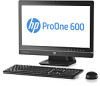
Figure 1-1 HP ProOne 600 G1 All-in-One The HP ProOne 600 G1 All-in-One offers the following features: ● Integrated All-in-One form factor ● Full HD IPS, LCD display (1920 x 1080) with LED backlighting ◦ 54.6-cm (21.5-inch) diagonal ● Swivel pad under base of stand ● Adjustable tilt ● Optional - HP ProOne 600 | Hardware Reference Guide - Page 8
HP SuperMulti DVD+/-RW SATA Optical Disc Drive, DVD-ROM Disc Drive, or Slim BDXL Blu-ray Writer ● Intel Q85 Express chipset ● Two SODIMM slots with up to 16 GB of DDR3 SDRAM memory and dual channel memory support support ● Integrated Gigabit Ethernet (Intel i217LM GbE LOM) ● Wireless connectivity - HP ProOne 600 | Hardware Reference Guide - Page 9
Increase volume 10 Mute microphone 11 Decrease brightness 12 Increase brightness Touch the icon area (7-12 above) to cause the icons to illuminate, then touch an icon to activate it. To change the volume or brightness, touch and hold the appropriate icon or touch it and repeat until the volume - HP ProOne 600 | Hardware Reference Guide - Page 10
Side components Figure 1-3 Side components Table 1-2 Side components Component 1 Hard disc drive activity LED 2 HP 6-in-1 media card reader (optional) 3 USB 3.0 port, fast-charging 4 USB 3.0 port 5 Microphone/line in jack Component 6 Headset/line out jack 7 Tray-load optical disc - HP ProOne 600 | Hardware Reference Guide - Page 11
Rear components Figure 1-4 Rear components Table 1-3 Rear components Component 1 Access panel 2 Access panel latches 3 Security lock slot 4 Power connector 5 (2) PS/2 mouse and keyboard connectors 6 (2) USB 2.0 ports Component 7 RJ-45 Gigabit Ethernet port 8 (2) USB 3.0 ports 9 - HP ProOne 600 | Hardware Reference Guide - Page 12
Keyboard features Figure 1-5 Keyboard features Table 1-4 Keyboard features Component 1 Sleep 2 Fast Reverse 3 Play/Pause 4 Stop 5 Fast Forward Component 6 Mute Volume 7 Decrease Volume 8 Increase Volume 9 Function 6 Chapter 1 Product features - HP ProOne 600 | Hardware Reference Guide - Page 13
positions CAUTION: Positioning the computer with the HP logo on the top or on the left is not supported. Adjusting the height-adjustable/recline stand (optional) This stand allows you to: ● adjust the computer height 110 mm (4.3 inches) ● rotate the computer position from landscape to portrait - HP ProOne 600 | Hardware Reference Guide - Page 14
WARNING! If the height-adjustable/recline stand is installed, before laying the computer down for service, first grasp the sides or backward up to +30 degrees to set it to a comfortable eye level. Figure 1-9 Adjusting tilt The tilt/swivel stand has a swivel pad on the underside that allows you to - HP ProOne 600 | Hardware Reference Guide - Page 15
Figure 1-10 Adjusting swivel Positioning the computer 9 - HP ProOne 600 | Hardware Reference Guide - Page 16
of the applicable instructions, cautions, and warnings in this guide. WARNING! To cords or cables. Arrange them so that no one may accidentally step on or trip over them. Do users, and provides important electrical and mechanical safety information. This guide is located on the Web at http://www.hp - HP ProOne 600 | Hardware Reference Guide - Page 17
procedures, be sure that you are discharged of static electricity by briefly touching a grounded metal object. See Electrostatic discharge on page 49 for more , and troubleshooting, refer to the Maintenance and Service Guide (available in English only) for your computer model at http://www.hp.com. - HP ProOne 600 | Hardware Reference Guide - Page 18
, from the computer. 2. Turn off the computer properly through the operating system, then turn off any external devices. 3. Remove the cable lock, if one is installed on the rear of the computer. 4. If the rear port cover is installed, remove the cover. 5. Disconnect the power cord connector from - HP ProOne 600 | Hardware Reference Guide - Page 19
Installing and removing the rear port cover Installing the rear port cover 1. Be sure that all cables are connected. 2. Place the cover against the computer, lining up the cable lock slot in the cover about 12 mm (0.5 inch) below the cable lock slot in the computer. Slide the cover up and into - HP ProOne 600 | Hardware Reference Guide - Page 20
a security lock The optional security lock enables you to secure your computer. A cable lock is a key lock device that has a wire cable attached. You attach one end of the cable to your desk (or other stationary object) and the other end of the cable to the cable lock slot on the - HP ProOne 600 | Hardware Reference Guide - Page 21
be broken. Turn the mouse off, then on again to restore the synchronization. NOTE: If the procedure does not work, remove and then reinsert the wireless keyboard and mouse receiver from the back of the computer and then synchronize the keyboard and mouse again. If synchronization still does not work - HP ProOne 600 | Hardware Reference Guide - Page 22
on the underside of the keyboard (1) and lift the batteries out of the battery compartment (2). Figure 2-8 Removing batteries from the wireless keyboard To remove batteries from the wireless mouse, remove the battery door on the underside of the mouse (1) and lift the batteries out of the battery - HP ProOne 600 | Hardware Reference Guide - Page 23
Attaching the computer to a mounting fixture You can remove the computer from the stand and install it on a wall, monitor arm, or other mounting fixture. There is a VESA mount under the computer stand that is used for mounting the computer. Table 2-1 Computer dimensions (without stand) Computer - HP ProOne 600 | Hardware Reference Guide - Page 24
/recline stand (optional) Installing a height-adjustable/recline stand To install the stand: 1. Place the computer face down on a soft flat surface. HP recommends that you set down a blanket, towel, or other soft cloth to protect the bezel and screen surface from scratches or other damage. 2. Engage - HP ProOne 600 | Hardware Reference Guide - Page 25
3. Tighten the four captive screws to secure the stand to the chassis. Figure 2-12 Securing the stand Removing a height-adjustable/recline stand To remove the stand: 1. Remove all removable media, such as compact discs or USB flash drives, from the computer. 2. Turn off the computer - HP ProOne 600 | Hardware Reference Guide - Page 26
Place the computer face down on a soft flat surface. HP recommends that you set down a blanket, towel, or other soft cloth to protect the bezel and screen surface from scratches or other damage. WARNING! Before laying the computer down for service, first grasp the sides of the display and raise the - HP ProOne 600 | Hardware Reference Guide - Page 27
tilt/swivel stand To install the stand: 1. Place the computer face down on a soft flat surface. HP recommends that you set down a blanket, towel, or other soft cloth to protect the bezel and screen surface from scratches or other damage. 2. Push the release button on the bottom of the stand and pull - HP ProOne 600 | Hardware Reference Guide - Page 28
4. Tighten the captive screws to secure the stand to the chassis. Figure 2-17 Securing the stand 5. Align the top of the back of the stand with the stand, and press it into place, working along the sides until it is in place. Figure 2-18 Installing the back of the stand Removing a tilt/swivel stand - HP ProOne 600 | Hardware Reference Guide - Page 29
devices that prohibit opening the computer. 5. Place the computer face down on a soft flat surface. HP recommends that you set down a blanket, towel, or other soft cloth to protect the bezel and screen surface from scratches or other damage. 6. Push the release button (1) on the bottom of the stand - HP ProOne 600 | Hardware Reference Guide - Page 30
display that does not have a DisplayPort connector, you can purchase a DisplayPort video adaptor from HP for your configuration. DisplayPort adapters and video cables are purchased separately. HP offers the following adapters: ● DisplayPort to VGA adapter ● DisplayPort to DVI adapter ● DisplayPort - HP ProOne 600 | Hardware Reference Guide - Page 31
3. If your second display has a DisplayPort connector, connect a DisplayPort cable directly between the DisplayPort connector on the rear of the computer and the DisplayPort connector on the second display. Figure 2-22 Connecting a DisplayPort cable Figure 2-23 Connecting a second display - HP ProOne 600 | Hardware Reference Guide - Page 32
4. If your second display does not have a DisplayPort connector, connect a DisplayPort video adapter to the DisplayPort connector of the computer. Then connect a cable (VGA, DVI. or HDMI, depending on your application) between the adapter and a second display. NOTE: When a DisplayPort adaptor is - HP ProOne 600 | Hardware Reference Guide - Page 33
Locating internal components The following sections contain procedures for removing and replacing these internal components: ● Memory ● Battery ● Hard disc drive, solid state drive, or self-encrypting drive ● Optical disc drive Figure 2-25 Locating internal components Component 1 Optical disc - HP ProOne 600 | Hardware Reference Guide - Page 34
. These memory sockets are populated with at least one preinstalled SODIMM. To achieve the maximum memory support, you can populate the system board with up SDRAMs are not supported NOTE: The system will not operate properly if you install unsupported SODIMM memory. HP offers upgrade memory for - HP ProOne 600 | Hardware Reference Guide - Page 35
assigned to dual channel and the remainder is assigned to single channel. If one channel will have more memory than the other, the larger amount should be soft flat surface. HP recommends that you set down a blanket, towel, or other soft cloth to protect the bezel and screen surface from scratches or - HP ProOne 600 | Hardware Reference Guide - Page 36
6. Slide the access panel latches toward the edges of the unit, then slide the access panel toward the top of the computer until it slides off the unit. Figure 2-26 Removing the access panel 7. To remove a memory module, press outward on the two latches on each side of the SODIMM (1), then pull the - HP ProOne 600 | Hardware Reference Guide - Page 37
press the SODIMM down (2) so that the latches lock it in place. Figure 2-28 Installing a memory module NOTE: A memory module can be installed in only one way. Match the notch on the module with the tab on the memory socket. 9. To replace the access panel, set the panel on the back - HP ProOne 600 | Hardware Reference Guide - Page 38
, be sure that you are discharged of static electricity by briefly touching a grounded metal object. NOTE: The lifetime of the lithium battery a soft flat surface. HP recommends that you set down a blanket, towel, or other soft cloth to protect the bezel and screen surface from scratches or other - HP ProOne 600 | Hardware Reference Guide - Page 39
lower right side of the fan. Figure 2-31 Locating the battery 7. To release the battery from its holder, squeeze the metal clamp that extends above one edge of the battery. When the battery pops up, lift it out (1). Replacing the battery 33 - HP ProOne 600 | Hardware Reference Guide - Page 40
8. To insert the new battery, slide one edge of the replacement battery under the holder's lip with the positive side up. Push the other edge down until the clamp snaps over the - HP ProOne 600 | Hardware Reference Guide - Page 41
. 4. Remove/disengage any security devices that prohibit opening the computer. 5. Place the computer face down on a soft flat surface. HP recommends that you set down a blanket, towel, or other soft cloth to protect the bezel and screen surface from scratches or other damage. Replacing drives 35 - HP ProOne 600 | Hardware Reference Guide - Page 42
6. Slide the access panel latches toward the edges of the chassis, then slide the access panel toward the top of the computer until it slides off the chassis. Figure 2-34 Removing the access panel 7. Pull the latch next to the lower side of the drive cage away from the cage to release it, then slide - HP ProOne 600 | Hardware Reference Guide - Page 43
8. Lift the latch on one side of the drive cage and pull the hard disc drive out of blue rubber grommets to use to install a replacement disc drive. Figure 2-37 Removing the mounting screws For instructions on installing a hard disc drive, see Installing a hard disc drive on page 40. Removing a 2.5- - HP ProOne 600 | Hardware Reference Guide - Page 44
5. Place the computer face down on a soft flat surface. HP recommends that you set down a blanket, towel, or other soft cloth to protect the bezel and screen surface from scratches or other damage. 6. Slide the access panel latches toward the edges of the chassis, then slide the access panel toward - HP ProOne 600 | Hardware Reference Guide - Page 45
. NOTE: The primary drive is the lower position in the drive cage. If only one drive is to be installed, it must occupy this position. Figure 2-41 Removing the disc drive(s) from the 2.5-inch drive adapter. For instructions on installing a hard disc drive, see Installing a hard disc drive on page - HP ProOne 600 | Hardware Reference Guide - Page 46
Installing a hard disc drive ● Installing a 3.5-inch hard disc drive ● Installing 2.5-inch hard disc drives Installing a 3.5-inch hard disc drive 1. Screw the four mounting screws into the 3.5-inch hard disc drive. Be sure to keep the blue rubber grommets behind each screw. Figure 2-42 Inserting the - HP ProOne 600 | Hardware Reference Guide - Page 47
3. With the 3.5-inch hard disc drive connector facing toward the center of the chassis, place the hard disc drive cage into the chassis and slide it toward the center until it snaps into place. Figure 2-44 Installing the 3.5-inch hard disc drive cage 4. To replace the access panel, set the panel on - HP ProOne 600 | Hardware Reference Guide - Page 48
sure that the connectors are at the opening of the adapter. NOTE: The primary drive is the lower position in the drive adapter. If only one drive is to be installed, it must occupy this position. 2. Fasten the four mounting screws with grommets into the sides of the 2.5-inch drive adapter - HP ProOne 600 | Hardware Reference Guide - Page 49
3. Slide the drive adapter holding the 2.5-inch drive or drives into the drive cage. Figure 2-47 inserting the 2.5-inch drive adapter into the drive cage Replacing drives 43 - HP ProOne 600 | Hardware Reference Guide - Page 50
4. Position the drive cage above its final site with the hard disc drive connectors facing toward the center of the chassis. If the drive cage contains a secondary (upper) drive, connect the SATA cable to the right of the drive cage to the secondary drive. Figure 2-48 Connecting the secondary 2.5- - HP ProOne 600 | Hardware Reference Guide - Page 51
. 4. Remove/disengage any security devices that prohibit opening the computer. 5. Place the computer face down on a soft flat surface. HP recommends that you set down a blanket, towel, or other soft cloth to protect the bezel and screen surface from scratches or other damage. Replacing drives 45 - HP ProOne 600 | Hardware Reference Guide - Page 52
6. Slide the access panel latches toward the edges of the chassis, then slide the access panel toward the top of the computer until it slides off the chassis. Figure 2-51 Removing the access panel 7. Lift the tab at the back of the optical disc drive enclosure to release the drive. Figure 2-52 - HP ProOne 600 | Hardware Reference Guide - Page 53
8. Remove the two screws securing the optical disc drive bracket to the drive. Figure 2-53 Removing the optical disc drive bracket 9. Secure the optical disc drive bracket to the new drive with the two screws. Figure 2-54 Attaching the optical disc drive bracket Replacing drives 47 - HP ProOne 600 | Hardware Reference Guide - Page 54
the side of the computer. Push the drive in firmly until it snaps into place. NOTE: The optical disc drive can be installed in only one way. Figure 2-55 Installing the optical disc drive 11. To replace the access panel, set the panel on the back of the computer, slightly above - HP ProOne 600 | Hardware Reference Guide - Page 55
grounded when touching a static-sensitive component or assembly. Grounding methods There are several methods for grounding. Use one or more HP authorized dealer, reseller, or service provider. NOTE: For more information on static electricity, contact an HP authorized dealer, reseller, or service - HP ProOne 600 | Hardware Reference Guide - Page 56
or damage the finish. ◦ Do not use cleaners that contain any petroleum based materials such as benzene, thinner, or any volatile substance to clean the screen or cabinet. These chemicals may damage the computer. 50 Appendix B Computer operating guidelines, routine care, and shipping preparation - HP ProOne 600 | Hardware Reference Guide - Page 57
cloth to gently wipe the screen surface. Never spray the cleaner directly on the screen surface. It may run changes while the drive is on, wait at least one hour before you turn off the power. If and have it checked by an authorized HP service provider. Shipping preparation Follow these suggestions - HP ProOne 600 | Hardware Reference Guide - Page 58
components 27 K keyboard features 6 removing batteries 16 synchronizing wireless 15 M memory installing 29 removing 29 SODIMMs specifications 28 inch hard disc drive 35 height-adjustable/recline stand 19 tilt/swivel stand 22 removing battery 32 rotation 7 S second display connection 24 52 Index - HP ProOne 600 | Hardware Reference Guide - Page 59
/recline, removing 19 tilt/swivel stand, installing 21 tilt/swivel stand, removing 22 swivel adjustment 8 synchronizing wireless keyboard and mouse 15 T tilt adjustment 8 tilt/swivel stand installing 21 removing 22 V ventilation guidelines 50 VESA mounting holes 17 W warnings and cautions 10
-
 1
1 -
 2
2 -
 3
3 -
 4
4 -
 5
5 -
 6
6 -
 7
7 -
8
-
9
-
10
-
11
-
12
-
13
-
14
-
15
-
16
-
17
-
18
-
19
-
20
-
21
-
22
-
23
-
24
-
25
-
26
-
27
-
28
-
29
-
30
-
31
-
32
-
33
-
34
-
35
-
36
-
37
-
38
-
39
-
40
-
41
-
42
-
43
-
44
-
45
-
46
-
47
-
48
-
49
-
50
-
51
-
52
-
53
-
54
-
55
-
56
-
57
-
58
-
59
 |
 |

Hardware Reference Guide
HP ProOne 600 G1 All-in-One