HP S10614 10000 Series Rack Reference Guide
HP S10614 Manual
 |
View all HP S10614 manuals
Add to My Manuals
Save this manual to your list of manuals |
HP S10614 manual content summary:
- HP S10614 | 10000 Series Rack Reference Guide - Page 1
HP10000 Series Rack Reference Guide December 2002 (Second Edition) Part Number 258200-002 - HP S10614 | 10000 Series Rack Reference Guide - Page 2
in this document is provided "as is" without warranty of any kind and is subject to change without notice. The warranties for HP products are set forth in the express limited warranty statements accompanying such products. Nothing herein should be construed as constituting an additional warranty - HP S10614 | 10000 Series Rack Reference Guide - Page 3
Support ...x HP Website...x Authorized Reseller...xi Reader's Comments...xi Chapter 1 Overview 10000 Series Racks...1-2 Rack Options ...1-3 Delivery Considerations 1-5 Installation Overview...1-5 Installation Service...1-6 Chapter 2 Configuration Factors Rack Configuration Software 2-1 Rack - HP S10614 | 10000 Series Rack Reference Guide - Page 4
the Rack Doors 3-3 Removing the Side Panels 3-7 Stabilizing the Rack ...3-8 Standalone Racks...3-8 Multiple Racks...3-10 Server/Storage Component into the Rack 4-18 Attaching the Cable Management Arm 4-20 Routing the Cables 4-23 Rack Option Kits...4-26 iv HP 10000 Series Rack Reference Guide - HP S10614 | 10000 Series Rack Reference Guide - Page 5
B Transportation Instructions Transportation Methods B-1 Air Transport...B-1 Land Transport ...B-2 Sea Transport ...B-2 Delivery Services...B-2 Inside Rack Delivery Service B-2 Expedited Rack Delivery Service B-3 Shipping/Delivery Considerations B-4 Index HP 10000 Series Rack Reference Guide v - HP S10614 | 10000 Series Rack Reference Guide - Page 6
About This Guide This guide provides step-by-step instructions for installation, and reference information for operation for the HP 10000 Series Rack. Important Safety Information Before installing this product, read the Important Safety Information document included with the server. Symbols on - HP S10614 | 10000 Series Rack Reference Guide - Page 7
: To reduce the risk of personal injury or damage to the Weight in lb equipment, observe local occupational health and safety requirements and guidelines for manual material handling. viii HP 10000 Series Rack Reference Guide - HP S10614 | 10000 Series Rack Reference Guide - Page 8
explain a concept or complete a task. NOTE: Text set off in this manner presents additional information to emphasize or supplement important points of the main text. HP 10000 Series Rack Reference Guide ix - HP S10614 | 10000 Series Rack Reference Guide - Page 9
Getting Help If you have a problem and have exhausted the information in this guide, you can get further information and other help in the following locations. Technical Support In North America, call the HP Technical Support Phone Center at 1-800-652-6672. This service is available 24 hours a day - HP S10614 | 10000 Series Rack Reference Guide - Page 10
800-345-1518. • In Canada, call 1-800-263-5868. • Elsewhere, see the HP website for locations and telephone numbers. Reader's Comments HP welcomes your comments on this guide. Please send your comments and suggestions by e-mail to [email protected]. HP 10000 Series Rack Reference Guide xi - HP S10614 | 10000 Series Rack Reference Guide - Page 11
allows you to decrease the footprint required to house your existing hardware while providing expansion capability. Racks and rack-mountable components are typically described using U measurements. For example, one U is 44.45 millimeters (1.75 inches) high. HP 10000 Series Rack Reference Guide 1-1 - HP S10614 | 10000 Series Rack Reference Guide - Page 12
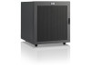
10000 Series Racks The 10000 Series racks offer the following features: • Interchangeable perforated front and split rear doors • Cable access panel on rear door • Perforated rack top with egress slot • Graphite metallic color Figure 1-1: 10000 Series racks 1-2 HP 10000 Series Rack Reference Guide - HP S10614 | 10000 Series Rack Reference Guide - Page 13
components operating within the rack Holds a monitor or other rack component Programmable switch panel with connection hardware used to switch a keyboard, monitor, and mouse among multiple servers Routes and organizes cables within the rack continued HP 10000 Series Rack Reference Guide 1-3 - HP S10614 | 10000 Series Rack Reference Guide - Page 14
information about these products, see the HP website at www.hp.com. Contact the nearest HP authorized reseller or service provider for information about ordering rack option kits. For the name of the nearest HP authorized reseller, see "About This Guide." 1-4 HP 10000 Series Rack Reference Guide - HP S10614 | 10000 Series Rack Reference Guide - Page 15
Stabilize the rack. 6. Bay multiple racks together. 7. Install products such as Power Distribution Units (PDUs) or switch boxes in sidewall locations. 8. Install products such as Uninterruptible Power System (UPS) units starting from the bottom of the rack. HP 10000 Series Rack Reference Guide 1-5 - HP S10614 | 10000 Series Rack Reference Guide - Page 16
guaranteed service providers. This installation service covers the entire hardware installation sequence, from unpacking the components to routing cabling and running a test of the system. For more information on HP support, see "About This Guide." 1-6 HP 10000 Series Rack Reference Guide - HP S10614 | 10000 Series Rack Reference Guide - Page 17
placement in the rack. Rack Configuration Software To help you plan your rack configuration more efficiently, HP provides Rack Builder Online, the browser-based rack configuration tool. The latest version of the software is available at www.hp.com. HP 10000 Series Rack Reference Guide 2-1 - HP S10614 | 10000 Series Rack Reference Guide - Page 18
and use it as your shopping list. After your rack configuration is in place, use Rack Builder Online to assist you in maintenance and upgrades. See the documentation accompanying the software utilities for installation and use of the software programs. 2-2 HP 10000 Series Rack Reference Guide - HP S10614 | 10000 Series Rack Reference Guide - Page 19
height of the rack. • Keyboard-The rack keyboard requires installation of a 1U Keyboard Drawer Rack Option Kit. • Monitor-The monitor requires installation of a Monitor/Utility Shelf Rack Option Kit unless you are using a rack-mountable flat panel monitor. HP 10000 Series Rack Reference Guide 2-3 - HP S10614 | 10000 Series Rack Reference Guide - Page 20
switch box is configured, use the CPU-to-Switch cable included with the server. The standard distance between the switch box and the keyboard, monitor, required for each row of bayed racks. • Stabilizing Feet-A stand-alone rack requires stabilizing feet. 2-4 HP 10000 Series Rack Reference Guide - HP S10614 | 10000 Series Rack Reference Guide - Page 21
for your rack environment. Space Requirements When deciding where to place your rack: • At rack to provide access to components. • At least 38 centimeters (15 inches) of clearance is needed around a power supply to facilitate servicing distribution requirements for your rack configuration: • The power - HP S10614 | 10000 Series Rack Reference Guide - Page 22
supplied with that option. Grounding Requirements For proper operation and safety, all powered rack-mountable components are required to be properly grounded in accordance with (NFPA-70, the equipment. The grounding plug is an important safety feature. 2-6 HP 10000 Series Rack Reference Guide - HP S10614 | 10000 Series Rack Reference Guide - Page 23
should not exceed the values in the following table. Table 2-1: Rack Internal Temperature Maximums Equipment Included HP rack-mountable servers HP rack-mountable options HP PDUs Other manufacturers' options Maximum Internal Rack Temperature 95°F/35°C 104°F/40°C 122°F/50°C See other manufacturers - HP S10614 | 10000 Series Rack Reference Guide - Page 24
top. Blanking Panels If the front of the rack is not completely filled with components, the remaining gaps between the components can cause changes in the airflow, which can adversely affect cooling within the rack. Cover these gaps with blanking panels. 2-8 HP 10000 Series Rack Reference Guide - HP S10614 | 10000 Series Rack Reference Guide - Page 25
Installation This chapter discusses the following topics: • Required tools • Checking the hardware • Removing the rack doors • Removing the side panels • Stabilizing the rack - Standalone racks - Multiple racks • Server/Storage vs. switching configurations HP 10000 Series Rack Reference Guide 3-1 - HP S10614 | 10000 Series Rack Reference Guide - Page 26
List that was shipped with your rack. Verify that you received all listed components. You will typically have extra fasteners after completing your rack configuration and component installation. IMPORTANT: Retain the extra fasteners for future use. 3-2 HP 10000 Series Rack Reference Guide - HP S10614 | 10000 Series Rack Reference Guide - Page 27
has side panels, also remove them before installing mounting brackets and other hardware. To remove the rack front door: 1. Unlock the door (1) and press the handle release button (2). The handle pops out. 2. Lift the handle up and out to open the door (3). 3 1 2 - HP S10614 | 10000 Series Rack Reference Guide - Page 28
top hinge pin (1). 4. Tilt the door out and lift to remove it from the bottom hinge bracket (2). 5. Lift the door out and away from the rack (3). Store the door in an upright position, taking care to protect it from damage. 2 3 1 Figure 3-2: Removing the front door - HP S10614 | 10000 Series Rack Reference Guide - Page 29
Preparing the Rack for Component Installation To remove the rack rear doors: 1. Rotate the handle to the right (1). 2. Pull the handle to open the doors (2). 1 2 Figure 3-3: Opening the rear doors HP 10000 Series Rack Reference Guide 3-5 - HP S10614 | 10000 Series Rack Reference Guide - Page 30
top hinge and down on the bottom hinge for each door (1). 4. Lift the rear doors off of the hinge brackets and remove them from the rack (2). Store the doors in an upright position, taking care to protect them from damage. 2 1 1 Figure 3-4: Removing the rear doors - HP S10614 | 10000 Series Rack Reference Guide - Page 31
the rack (3). Store the panels in an upright position, taking care to protect them from damage. 2 1 3 Figure 3-5: Removing the rack side panels Instructions for replacing the side panels are given in the Side Panel Rack Option Kit Installation Instructions card. HP 10000 Series Rack Reference Guide - HP S10614 | 10000 Series Rack Reference Guide - Page 32
weight of the rack rests on the leveling feet, and not on the casters. The casters are designed only as an aid in moving the rack into position. They are not designed to support the weight of the rack and may become damaged if relied on to support the rack. 3-8 HP 10000 Series Rack Reference Guide - HP S10614 | 10000 Series Rack Reference Guide - Page 33
for bayed racks. Attach one modified foot to the front of the rack when you place it between third-party racks. NOTE: The Stabilizer Rack Option Kit components come standard with each 10622 rack. Figure 3-6: Full-size stabilizing feet attached (top view) HP 10000 Series Rack Reference Guide 3-9 - HP S10614 | 10000 Series Rack Reference Guide - Page 34
rack to be used in server/storage or switching applications. The 10842 rack arrives in a server/storage configuration with internal mounting rails that are front-justified, providing the customer greater room in the rear of the rack for cable management. 3-10 HP 10000 Series Rack Reference Guide - HP S10614 | 10000 Series Rack Reference Guide - Page 35
• Using the template • Inserting the cage nuts • Preparing and installing the rails • Preparing the component • Installing the component - Inserting the component into the rack - Attaching the cable management arm - Attaching the cables - Routing the cables HP 10000 Series Rack Reference Guide 4-1 - HP S10614 | 10000 Series Rack Reference Guide - Page 36
, always be sure that the rack is adequately stabilized before extending a component outside the rack. A rack may become unstable if more than installed does not impede airflow to the rack-mountable ProLiant servers or increase the internal rack temperature beyond the specified maximum rating. - HP S10614 | 10000 Series Rack Reference Guide - Page 37
instructions servers, do not put all of the UPS units into one rack. Instead distribute them evenly in the bottom positions of each rack. • Allow a minimum clearance of 76 centimeters (30 inches) between the wall and the rear of the rack to provide adequate access for installation and service. HP - HP S10614 | 10000 Series Rack Reference Guide - Page 38
arm to the rack and then to the component. 7. Attach any cables and power cords, being sure that you adhere to all cautions and warnings contained in the individual component installation instructions. 8. Remove the cable access panel and route the cables. 4-4 HP 10000 Series Rack Reference Guide - HP S10614 | 10000 Series Rack Reference Guide - Page 39
the attachment points for rack-mounting brackets, rails, components, or cage nuts on the front of the rack. 4. Use the back of the template to mark the attachment points for rack-mounting brackets, rails, components, or cage nuts on the back of the rack. HP 10000 Series Rack Reference Guide 4-5 - HP S10614 | 10000 Series Rack Reference Guide - Page 40
cage nut. 3. Use the insertion tool to pull the cage nut through the hole until the top lip snaps into position. Figure 4-2: Inserting cage nuts 4-6 HP 10000 Series Rack Reference Guide - HP S10614 | 10000 Series Rack Reference Guide - Page 41
instructions below are for standard installations. For specific installation instructions, please refer to the documentation included with your component. There are two types of rack nuts slightly to stabilize the rail-mounting brackets during installation. HP 10000 Series Rack Reference Guide 4-7 - HP S10614 | 10000 Series Rack Reference Guide - Page 42
, securing the adjustable fixed rail to the front of the rack. NOTE: After installing your components, insert at least one more screw into each adjustable rail for additional support. Figure 4-4: Securing the adjustable fixed rail to the front of the rack 4-8 HP 10000 Series Rack Reference Guide - HP S10614 | 10000 Series Rack Reference Guide - Page 43
: After installing your components, insert at least one more screw into each adjustable rail for additional support. Figure 4-5: Securing the adjustable fixed rail to the rear of the rack 3. Retighten the wing nuts on the adjustable rails. The adjustable fixed rails are now ready for installation - HP S10614 | 10000 Series Rack Reference Guide - Page 44
the component rail from the sliding rail assembly. NOTE: You will attach the component rail to the component before you insert the unit into the rack. 2 1 Figure 4-6: Removing the component rail from the sliding rail assembly 4-10 HP 10000 Series Rack Reference Guide - HP S10614 | 10000 Series Rack Reference Guide - Page 45
standard rack-mounting brackets. All of the screw holes may not be used, depending on the component you are installing. Check the documentation shipped with your component to see which screws need to be installed. 1 2 Figure 4-7: Rack-mounting brackets HP 10000 Series Rack Reference Guide 4-11 - HP S10614 | 10000 Series Rack Reference Guide - Page 46
move forward on ball bearings. b. The back of the sliding rail assembly (2) has a stop for the inner slide. NOTE: While matching fronts, lay one rack-mounting bracket and one sliding rail assembly together so that the screw holes are aligned. 2 1 Figure 4-8: Orienting the sliding rail assembly 4-12 - HP S10614 | 10000 Series Rack Reference Guide - Page 47
8-32 × 3/8 screw. 7. Adjust the inner slide again and insert the last 8-32 × 3/8 screw (3) into the exposed hole. 1 2 3 Figure 4-9: Attaching the sliding rail assembly to the rack-mounting brackets The sliding rails are now ready for installation. HP 10000 Series Rack Reference Guide 4-13 - HP S10614 | 10000 Series Rack Reference Guide - Page 48
Installing Components Installing the Sliding Rails 1. Align and secure the front of the sliding rail to the front of the rack with two M6 × 16 screws. NOTE: The tabs on the front of the sliding rails help you align them correctly with the mounting rails. Figure 4- - HP S10614 | 10000 Series Rack Reference Guide - Page 49
component for complete installation instructions. Adjustable Fixed Rails If the component mounts with fixed rails, typically there is nothing additional to install on the component. The component slides into place along the rails you installed in the rack. HP 10000 Series Rack Reference Guide 4-15 - HP S10614 | 10000 Series Rack Reference Guide - Page 50
you need to install the component rails on the component before you can insert it into the rack. 1. Locate the component rails that you set aside when they were removed from the sliding rails . Figure 4-12: Attaching the component rails to the component 4-16 HP 10000 Series Rack Reference Guide - HP S10614 | 10000 Series Rack Reference Guide - Page 51
× 1/4 screws to attach the bracket that supports the cable management arm to the component. NOTE: The cable management arm is installed after the component is installed into the rack. Figure 4-13: Attaching the cable management arm bracket to the component HP 10000 Series Rack Reference Guide 4-17 - HP S10614 | 10000 Series Rack Reference Guide - Page 52
rack manual rack, the product is unstable when not fastened to the rails. Inserting the Component into the Rack IMPORTANT: Read and adhere to the cautions and warnings in this section. To install a component into the rack rack. 2. Fully extend the sliding rails. 3. With the unit well supported - HP S10614 | 10000 Series Rack Reference Guide - Page 53
that, the ball bearings should slide easily. 5. Using the cage nuts, tighten the thumbscrews on the front of the unit to secure it to the rack. I 0 Figure 4-14: Inserting the component into the rack HP 10000 Series Rack Reference Guide 4-19 - HP S10614 | 10000 Series Rack Reference Guide - Page 54
attach the cable management arm to the bracket you installed on the component earlier. Figure 4-15: Attaching the cable management arm to the bracket 4-20 HP 10000 Series Rack Reference Guide - HP S10614 | 10000 Series Rack Reference Guide - Page 55
cable management arm to the rail with two 10-32 × 5/8 screws. NOTE: As you slide the unit in and out of the front of the rack, the cable management arm collapses and extends so that the cables remain connected to the unit and stay untangled. Figure 4-16: Attaching the cable management - HP S10614 | 10000 Series Rack Reference Guide - Page 56
selection switch to the appropriate position. c. Attach the AC power cord to the unit. Figure 4-17: Attaching the AC power cord to the component 4-22 HP 10000 Series Rack Reference Guide - HP S10614 | 10000 Series Rack Reference Guide - Page 57
. 3. Route the bundled cables over the top of the cable management arm and down the cable conduit, if present. Figure 4-18: Routing the cables for server/storage applications 4. Remove the cable access panel, if present. HP 10000 Series Rack Reference Guide 4-23 - HP S10614 | 10000 Series Rack Reference Guide - Page 58
the hinge bracket (4). Store the panel in an upright position, taking care to protect it from damage. 3 3 4 1 2 Figure 4-19: Removing the cable access panel 4-24 HP 10000 Series Rack Reference Guide - HP S10614 | 10000 Series Rack Reference Guide - Page 59
unit. NOTE: If you are not using a power distribution unit, route the power cords directly to a properly rated and grounded AC wall or floor outlet. HP 10000 Series Rack Reference Guide 4-25 - HP S10614 | 10000 Series Rack Reference Guide - Page 60
-inch Rail Adapter Option Kit • Cable Management D-Ring Rack Option Kit • Fan (110V/220V) Rack Option Kit • Ground Bonding Rack Option Kit • Side Panel Rack Option Kit • Stabilizer Rack Option Kit For complete information see the HP website at www.hp.com. 4-26 HP 10000 Series Rack Reference Guide - HP S10614 | 10000 Series Rack Reference Guide - Page 61
inches) 610 mm (24 inches) 1346 mm (53 inches) 1219 mm (48 inches) 813 mm (32 inches) 80 kg (176 lbs) 102 kg (225 lbs) HP 10000 Series Rack Reference Guide 5-1 - HP S10614 | 10000 Series Rack Reference Guide - Page 62
) Weight Operating Shipping Height Depth Width Height Depth Width Table 5-3: Model 10642 Dimensions Cabinet size Shipping size (with packing materials) Weight Operating Shipping Height Depth Width ) 813 mm (32 inches) 115 kg (253 lbs) 148 kg (325 lbs) 5-2 HP 10000 Series Rack Reference Guide - HP S10614 | 10000 Series Rack Reference Guide - Page 63
inches) 610 mm (24 inches) 2438 mm (96 inches) 1219 mm (48 inches) 813 mm (32 inches) 111 kg (245 lbs) 129 kg (284 lbs) HP 10000 Series Rack Reference Guide 5-3 - HP S10614 | 10000 Series Rack Reference Guide - Page 64
a grounded surface before removing them from their containers. • Avoid touching pins, leads, or circuitry. • Always be properly grounded when touching a static-sensitive component or assembly. HP 10000 Series Rack Reference Guide A-1 - HP S10614 | 10000 Series Rack Reference Guide - Page 65
• Use conductive field service tools. • Use a portable field service kit with a folding HP authorized reseller install the part NOTE: For more information on static electricity, or assistance with product installation, contact your HP authorized reseller. A-2 HP 10000 Series Rack Reference Guide - HP S10614 | 10000 Series Rack Reference Guide - Page 66
, and double-stacking is not allowed. CAUTION: If your rack is an integrated model, it MUST be transported upright. If this is not possible, remove all components from the rack and prepare them for delivery, or choose an alternative transportation method. HP 10000 Series Rack Reference Guide B-1 - HP S10614 | 10000 Series Rack Reference Guide - Page 67
Transportation Instructions Because of the dimensions and the weight of the racks, check with carriers for their limitations before dispatching. Land Transport All racks can be shipped by common carriers. Carriers providing air ride capabilities are preferred. Ship racks upright on their pallets. Do - HP S10614 | 10000 Series Rack Reference Guide - Page 68
is provided as required. • Shipment is made by an air carrier selected by HP. • Delivery service is for a single rack. Limitations • This service is available only in the continental United States, Alaska, and Hawaii. • Inside rack delivery is not included. HP 10000 Series Rack Reference Guide B-3 - HP S10614 | 10000 Series Rack Reference Guide - Page 69
possible while still on the pallet. Then remove the rack from the pallet and roll the rack on its casters, being careful to keep the rack from tipping. Ideally, the palletized rack should be moved to its final destination and then removed from the pallet. B-4 HP 10000 Series Rack Reference Guide - HP S10614 | 10000 Series Rack Reference Guide - Page 70
cords 4-22 authorized, service provider 1-4 B balance, rack 2-3 ballast rack option kit 1-3 baying offset rack option kit 1-3 baying rack option kit 1-3 Best around power supply 2-5 between wall and rack 4-3 rack back 2-5 rack front 2-5 to unpack 2-5 HP 10000 Series Rack Reference Guide Index-1 - HP S10614 | 10000 Series Rack Reference Guide - Page 71
of damage from A-1 expedited delivery service B-3 F fan rack option kit 1-3 features cable access panel 1-2 color 1-2 HP 10000 Series racks 1-2 interchangeable doors 1-2 perforated front door 1-2 perforated rack top 1-2 perforated split rear doors 1-2 Rack Builder Online 2-2 fixed rails installation - HP S10614 | 10000 Series Rack Reference Guide - Page 72
component installation 4-3 H hardware shipped with rack 3-2 heel straps, using A-2 height, rack configuration considerations 2-3 HP 10000 Series racks features 1-2 illustration 1-2 option kits 1-3 overview 1-1 HP authorized service provider 1-4 HP Rack Kit Components List 3-2 I important cautions - HP S10614 | 10000 Series Rack Reference Guide - Page 73
Build It Mode 2-2 Let Me Build It Mode 2-2 modes of operation 2-2 rack configuration software 2-1 drag and drop 2-2 features 2-2 graphics 2-2 labeling 2-2 multiple-rack configuration 2-2 reports 2-2 third-party reports 2-2 rack configuration utility 1-5 Index-4 HP 10000 Series Rack Reference Guide - HP S10614 | 10000 Series Rack Reference Guide - Page 74
3-2 routing cables 4-23 S safety information, grounding requirements 2-6 sea transport of rack B-2 server console switch 1-3 placement 2-3 required parts 2-4 server/storage configurations 3-10 service, installation 1-6 setup, rack, completing 3-1 shipping by air B-1 by land B-2 by sea B-2 receiving - HP S10614 | 10000 Series Rack Reference Guide - Page 75
2-7 violation problems 2-7 template, using 4-5 TFT5600 rackmount keyboard and monitor rack option kit 1-4 third-party options 4-2 third-party support, Rack Builder Online 2-2 tips, multiple-rack configurations 3-10 tools needed 3-2 tools, conductive field service type A-2 transporting rack by air
-
 1
1 -
 2
2 -
 3
3 -
 4
4 -
 5
5 -
 6
6 -
 7
7 -
8
-
9
-
10
-
11
-
12
-
13
-
14
-
15
-
16
-
17
-
18
-
19
-
20
-
21
-
22
-
23
-
24
-
25
-
26
-
27
-
28
-
29
-
30
-
31
-
32
-
33
-
34
-
35
-
36
-
37
-
38
-
39
-
40
-
41
-
42
-
43
-
44
-
45
-
46
-
47
-
48
-
49
-
50
-
51
-
52
-
53
-
54
-
55
-
56
-
57
-
58
-
59
-
60
-
61
-
62
-
63
-
64
-
65
-
66
-
67
-
68
-
69
-
70
-
71
-
72
-
73
-
74
-
75
 |
 |

HP10000 Series Rack
Reference Guide
December 2002 (Second Edition)
Part Number 258200-002