HP SR5550F Upgrading and Servicing Guide
HP SR5550F - Compaq Presario - 3 GB RAM Manual
 |
UPC - 883585960545
View all HP SR5550F manuals
Add to My Manuals
Save this manual to your list of manuals |
HP SR5550F manual content summary:
- HP SR5550F | Upgrading and Servicing Guide - Page 1
Upgrading and Servicing Guide - HP SR5550F | Upgrading and Servicing Guide - Page 2
services. Nothing herein should be construed as constituting an additional warranty. HP shall not be liable for technical or editorial errors or omissions contained herein. HP in the United States and/or other countries/regions. HP supports lawful use of technology and does not endorse or encourage - HP SR5550F | Upgrading and Servicing Guide - Page 3
Inside the Computer 7 Removing and Replacing Drives 8 Removing an Optical Drive 8 Adding or Replacing an Optical Drive 9 Removing the HP Pocket Media or Diskette or Hard Disk Drive 11 Adding or Replacing the HP Pocket Media or Diskette or Hard Disk Drive 13 Removing the Memory Card Reader 15 - HP SR5550F | Upgrading and Servicing Guide - Page 4
iv Table of Contents - HP SR5550F | Upgrading and Servicing Guide - Page 5
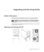
Information" in the Warranty and Support Guide before installing and connecting your system to the electrical power system. The Upgrading and Servicing Guide provides instructions on how to remove and replace hardware components of your PC. Opening and Closing the PC Upgrading and Servicing Guide 1 - HP SR5550F | Upgrading and Servicing Guide - Page 6
to upgrade or service the PC: 1 These procedures assume familiarity with the general terminology associated with personal computers and with the safety practices and regulatory compliance required for using and modifying electronic equipment. 2 Write down and save the system model and serial numbers - HP SR5550F | Upgrading and Servicing Guide - Page 7
as the monitor. 5 If you installed an add-in card, install any software drivers supplied by the card manufacturer. Removing the Side Panel 1 See "Before Opening the PC" on page 2. 2 Loosen the thumbscrew (A) that secures the side panel to the PC chassis. You may need to use a screwdriver the first - HP SR5550F | Upgrading and Servicing Guide - Page 8
attached properly. 2 Ensure that the hole for the thumbscrew aligns with the hole in the chassis, and then replace the thumbscrew (A). 3 See "After Closing the PC" on page 3. 4 Upgrading and Servicing Guide - HP SR5550F | Upgrading and Servicing Guide - Page 9
or replacing an optical drive, memory card reader, an HP Pocket Media Drive, diskette drive, or the hard disk drive. 1 Pull the three tabs (B) away from the outside edge of the chassis. B 2 Swing the front panel away from the chassis toward the left to remove it. Upgrading and Servicing Guide 5 - HP SR5550F | Upgrading and Servicing Guide - Page 10
on the right side of the front panel into the three holes on the right side of the chassis until the panel snaps into place. 6 Upgrading and Servicing Guide - HP SR5550F | Upgrading and Servicing Guide - Page 11
combination drive, or HP Personal Media Drive bay C HP Pocket Media Drive bay, a hard disk drive, or a diskette (floppy) drive (select models) D Memory card reader (select models) E Front connector panel (no replacement instructions) F Hard disk drive and space for a second hard disk drive (located - HP SR5550F | Upgrading and Servicing Guide - Page 12
Removing and Replacing Drives Your PC has several drives that you can replace or upgrade. See the preceding topic, "Locating Components Inside the Computer" on page 7 for drive type and location. The hard disk drive is either a Serial ATA (advanced technology attachment) drive, which uses a narrow - HP SR5550F | Upgrading and Servicing Guide - Page 13
power, data, and the sound cable, if available, from the back of the optical drive you want to remove. For most drive cables, use a gentle rocking motion to free the plug. For Serial ATA hard disk drive cables, press the latch (select models the knockout plate. A B Upgrading and Servicing Guide 9 - HP SR5550F | Upgrading and Servicing Guide - Page 14
, make sure to connect the data cable labeled Master to the primary hard disk drive, and the data cable labeled Slave to the secondary hard disk drive. If the data cable is not connected correctly, the PC is unable to locate the hard disk drive and data may be lost. 10 Upgrading and Servicing Guide - HP SR5550F | Upgrading and Servicing Guide - Page 15
and to remove the front panel. See "Opening and Closing the PC" on page 1. 2 Release the HP Pocket Media or diskette (floppy), or hard disk drive, by removing the two screws on the side of the drive, and then slide the drive part way out of the front of the chassis. Upgrading and Servicing Guide 11 - HP SR5550F | Upgrading and Servicing Guide - Page 16
3 Disconnect the power and data cables from the back of the drive by squeezing the two latches and pulling the cable. MASTER SLAVE To CPU 4 Pull the drive out through the front of the chassis. 12 Upgrading and Servicing Guide - HP SR5550F | Upgrading and Servicing Guide - Page 17
two screw holes on the side of the drive, and then attach the two screws. For the HP Pocket Media and diskette (floppy) drive, make sure to insert the screw into the holes labeled (1). For a hard disk drive, make sure to insert the screw into the holes labeled HDD. Upgrading and Servicing Guide 13 - HP SR5550F | Upgrading and Servicing Guide - Page 18
4 Connect the power and data cables to the back of the HP Pocket Media, diskette (floppy), or hard disk drive. A B MASTER C SLAVE To CPU A - Connect to a primary hard disk drive. B - Connect to a secondary hard disk drive (select models only). C - Connect to the PC motherboard. 5 Complete the - HP SR5550F | Upgrading and Servicing Guide - Page 19
card reader, sliding the reader to the left to loosen it, and then pulling the memory card reader part way out of the front of the chassis. 3 Disconnect the cable from the back of the memory card reader. 4 Pull the memory card reader out of the front of the chassis. Upgrading and Servicing Guide - HP SR5550F | Upgrading and Servicing Guide - Page 20
hole on the right side of the memory card reader, and then insert the screw to secure the memory card reader to the chassis. 5 Complete the procedures to replace the front panel, replace the side panel, and close the PC. See "Opening and Closing the PC" on page 1. 16 Upgrading and Servicing Guide - HP SR5550F | Upgrading and Servicing Guide - Page 21
the computer gently on its side. 3 Remove the two screws that secure the hard disk drive cage to the chassis. 4 Push down the latch on the side of the hard disk drive cage, and then slide the hard disk drive cage away from the bottom of the chassis as shown below. Upgrading and Servicing Guide 17 - HP SR5550F | Upgrading and Servicing Guide - Page 22
drive cables, press the latch (5) (select models only) in the center of each plug (6), and pull the plug from the drive connector. 6 5 2 1 Disconnecting the Serial ATA hard disk drive cables MASTER SLAVE To CPU Disconnecting the Parallel ATA hard disk drive cables 18 Upgrading and Servicing Guide - HP SR5550F | Upgrading and Servicing Guide - Page 23
cage. NOTE: If you are replacing an old drive with a new drive, remove the four guide screws from the old drive, and use the screws to install the new drive. If you are installing a second hard disk drive, use four standard 6-32 screws that you purchase separately. Upgrading and Servicing Guide 19 - HP SR5550F | Upgrading and Servicing Guide - Page 24
drive cage (A) should be aligned with the screw holes on the chassis (B). A B 4 Align the four guides on the bottom of the hard disk drive cage with the holes on the back of the chassis, and then slide it down toward the bottom of the chassis until it locks into place. 20 Upgrading and Servicing - HP SR5550F | Upgrading and Servicing Guide - Page 25
models only). C - Connect to the PC motherboard. 6 Attach the two screws that secure the hard disk drive cage to the chassis. 7 Complete the procedures to replace the front panel, replace the side panel, and close the PC. See "Opening and Closing the PC" on page 1. Upgrading and Servicing Guide - HP SR5550F | Upgrading and Servicing Guide - Page 26
ones. The motherboard contains sockets for DDR DIMMs (double data rate dual in-line memory modules). The exact number of sockets and type of DDR memory module depends on which model PC you have. DDR DIM To determine which type and speed of memory module your PC uses, and for specific memory module - HP SR5550F | Upgrading and Servicing Guide - Page 27
, put the new memory module in the same memory slot from which the old memory was removed. Or If you are adding a memory module, install the new module into the socket nearest the preinstalled module, and install additional modules in the next available sockets. Upgrading and Servicing Guide 23 - HP SR5550F | Upgrading and Servicing Guide - Page 28
. A flat-head and a Phillips screwdriver are needed to remove, replace, or add an add-in card. NOTE: A power supply upgrade may be required for certain graphics card upgrades. Check with the graphics card supplier for more information about power supply requirements. 24 Upgrading and Servicing Guide - HP SR5550F | Upgrading and Servicing Guide - Page 29
the card against the other components. Store the old card in the anti-static packaging that contained your new card. A 6 If you are not replacing the old add-in card with a new add-in card, close the open slot by inserting the metal slot cover into the opened slot. Upgrading and Servicing Guide 25 - HP SR5550F | Upgrading and Servicing Guide - Page 30
and close the PC. See "Opening and Closing the PC" on page 1. NOTE: If the new card or device isn't working, read through the card manufacturer's installation instructions and recheck all connections, including those to the card, power supply, keyboard, and monitor. 26 Upgrading and Servicing Guide - HP SR5550F | Upgrading and Servicing Guide - Page 31
battery on the motherboard provides backup power for the PC's timekeeping ability. The memory modules or cables you removed. 8 Set the chassis upright. 9 Complete the procedure to replace the side panel, and to close the PC. See "Opening and Closing the PC" on page 1. Upgrading and Servicing Guide - HP SR5550F | Upgrading and Servicing Guide - Page 32
Part number: 5991-6985
-
 1
1 -
 2
2 -
 3
3 -
 4
4 -
 5
5 -
 6
6 -
 7
7 -
8
-
9
-
10
-
11
-
12
-
13
-
14
-
15
-
16
-
17
-
18
-
19
-
20
-
21
-
22
-
23
-
24
-
25
-
26
-
27
-
28
-
29
-
30
-
31
-
32
 |
 |

Upgrading and Servicing Guide