HP Scitex FB7500 User Instructions Replacing a Print Head
HP Scitex FB7500 Manual
 |
View all HP Scitex FB7500 manuals
Add to My Manuals
Save this manual to your list of manuals |
HP Scitex FB7500 manual content summary:
- HP Scitex FB7500 | User Instructions Replacing a Print Head - Page 1
Replacing a Print Head - HP Scitex FB7500 | User Instructions Replacing a Print Head - Page 2
sure that the UV system is powered off. 2 Close all the taps on the secondary tanks on both sides of the bridge (total of 12). 3 Manually open the upper hoods of the printing bridge, as shown in Figure 8-1. HP Scitex FB7500 Operator Manual - HP Scitex FB7500 | User Instructions Replacing a Print Head - Page 3
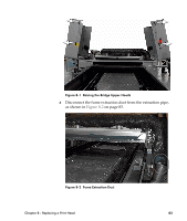
Figure 8-1 Raising the Bridge Upper Hoods 4 Disconnect the fume extraction duct from the extraction pipe, as shown in Figure 8-2 on page 83. Figure 8-2 Fume Extraction Duct Chapter 8 - Replacing a Print Head 83 - HP Scitex FB7500 | User Instructions Replacing a Print Head - Page 4
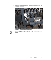
5 Manually raise the bridge by turning the lifting switch, as shown in Figure 8-3. Note Figure 8-3 Printing Bridge Lifting Switch Use a small 2-step ladder to climb the bridge and access the print heads. HP Scitex FB7500 Operator Manual - HP Scitex FB7500 | User Instructions Replacing a Print Head - Page 5
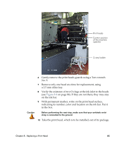
Print heads Correct position of the machine operator 2-step ladder 6 Gently remove the print heads guards using a Torx wrench No. 9. 7 Remove only one head at a time for replacement, using a 2.5 mm Allen key. 8 Verify the existence of two O-rings at the ink inlet to the heads (see Figure 8-4 on - HP Scitex FB7500 | User Instructions Replacing a Print Head - Page 6
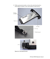
11 With a permanent marker, write on the print head surface, indicating its number, color and location on the ink bar. Catalog number Notch Ink inlet O-ring Positioning pin A1 Figure 8-4 Print Head Structure HP Scitex FB7500 Operator Manual - HP Scitex FB7500 | User Instructions Replacing a Print Head - Page 7
12 Verify that the two O-rings are on the ink inputs. 13 Visually check that the registration pins are clean. 14 Verify that the slot in the ink bar is clean. Slot for print head Ink feeding holes Print head inserted into slot Figure 8-5 Ink Bar 15 Screw out the two screws of the print head until - HP Scitex FB7500 | User Instructions Replacing a Print Head - Page 8
screws look identical, but the left one is marked as "A1" (see Figure 8-4 on page 86) and serves for precise positioning of the print head. HP Scitex FB7500 Operator Manual - HP Scitex FB7500 | User Instructions Replacing a Print Head - Page 9
18 Hold the print head parallel to the ink bar and carefully insert it into its slot (with the protective strip). When the head is almost inside, hold the first screw with one hand and with your other hand pull the strip out. Then hold the second screw with this hand and continue to insert the head - HP Scitex FB7500 | User Instructions Replacing a Print Head - Page 10
PIC board and damage to the pins of the connectors. • Repeat this until all the screws are tightened. 31 Perform the Trimming procedure. For detailed instructions refer to ACT User Guide supplied on the ACT DVD in the HP Scitex FB7500 Documentation Kit. HP Scitex FB7500 Operator Manual
-
 1
1 -
 2
2 -
 3
3 -
 4
4 -
 5
5 -
 6
6 -
 7
7 -
8
-
9
-
10
 |
 |

Replacing a Print Head