HP StorageWorks 6400/8400 HP StorageWorks power UID replacement instructions (
HP StorageWorks 6400/8400 - Enterprise Virtual Array Manual
 |
View all HP StorageWorks 6400/8400 manuals
Add to My Manuals
Save this manual to your list of manuals |
HP StorageWorks 6400/8400 manual content summary:
- HP StorageWorks 6400/8400 | HP StorageWorks power UID replacement instructions ( - Page 1
StorageWorks power UID replacement instructions About this document For the latest documentation, go to http://www.hp.com/support/ manuals, and select your product. The information contained herein is subject to change without notice. The only warranties for HP products and services are set forth - HP StorageWorks 6400/8400 | HP StorageWorks power UID replacement instructions ( - Page 2
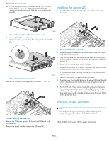
EVA: Power down the array (controller enclosure and disk enclosures) with HP Command View EVA or, on the EVA4400 only, the Web-based operator control panel (WOCP). Powering down the controller enclosure also removes power from the disk enclosures. 2. Remove all cabling from the external enclosure - HP StorageWorks 6400/8400 | HP StorageWorks power UID replacement instructions ( - Page 3
UID board (1, Figure 5). 2 3 1 15807 Figure 6 Installing the power UID 2. Align the board on the enclosure and secure the board and bezel ring with a T-15 screw (2). 3. Plug the UID cable from the midplane board (on disk enclosures) or riser card (on controller enclosure) into the connector on the
-
 1
1 -
 2
2 -
 3
3
 |
 |
HP StorageWorks
power UID replacement
instructions
These instructions apply to the MSA6X/7X, Proliant
DL320S, EVA4400, EVA6400, and EVA8400 product
families.
© Copyright 2009 Hewlett-Packard Development Company, L.P.
Second edition: February 2009
The information in this document is subject to change without notice.
Printed in Puerto Rico
www.hp.com
*533484-001*
About this document
For the latest documentation, go to
h
t
tp://w
w
w
.hp
.co
m/su
ppo
r
t/
man
uals
, and select your product.
The information contained herein is subject to change without notice.
The only warranties for HP products and services are set forth in the
express warranty statements accompanying such products and services.
Nothing herein should be construed as constituting an additional
warranty. HP shall not be liable for technical or editorial errors or
omissions contained herein.
WARRANTY STATEMENT: To obtain a copy of the warranty for this
product, see the warranty information website:
h
t
tp://w
w
w
.hp
.co
m/
go/s
t
o
r
age
w
ar
r
an
t
y
Before you begin
CAUTION:
Parts can be damaged by electrostatic discharge. Use proper
anti-static protection. Refer to the documentation that shipped
with your system for additional information.
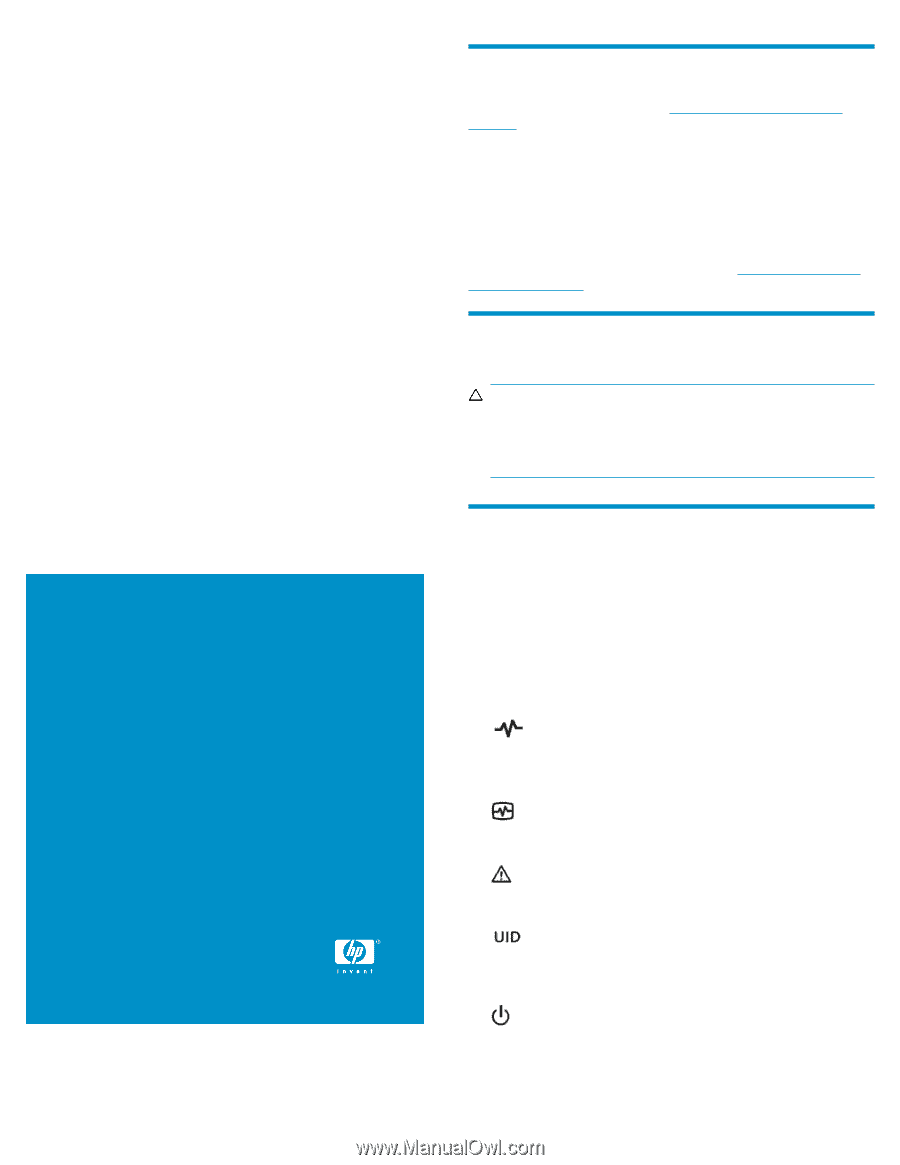
Verifying component failure
Improper or failed operation of the LEDs on the power UID may indicate
a replacement is necessary.
Proper LED operation for the MSA6X/7X is displayed as:
•
Blue = Identified
•
Blue flashing = Active remote management
•
Off = No active remote management
Proper LED operation for the EVA is displayed as:
•
= Enclosure external health (controller enclosure only). Solid
green indicates the enclosure is powered on. Blinking green indicates
a power off has been initiated by holding down the power button
for 4 to 5 seconds.
•
= Enclosure external health (disk enclosure only). Solid green
indicates the enclosure is operating normally. Blinking green indicates
power up.
•
= Enclosure fault warning. Flashing amber indicates a fault of
lesser importance, while solid amber indicates a fault of greater im-
portance.
•
= Unit identification. Push switch to illuminate solid blue; push
again to turn off. The UID mimics the status of the UID at the front of
the enclosure. A remote session from the management card or HP
Command View EVA can also illuminate the LED.
•
= Bi-color On/Standby button switch. Green indicates power
is applied and amber indicates standby power.
Page 1