HP Superdome SX2000 Installation Guide, Sixth Edition - HP Integrity Superdome - Page 42
Checking Voltage, Wall Receptacle Pinouts, WARNING
 |
View all HP Superdome SX2000 manuals
Add to My Manuals
Save this manual to your list of manuals |
Page 42 highlights
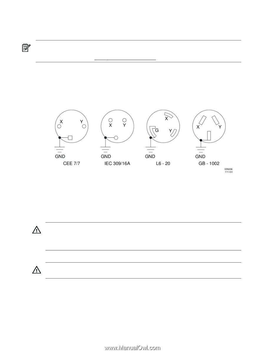
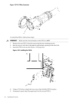
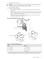
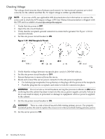
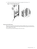
Checking Voltage The voltage check ensures that all phases (and neutral, for international systems) are wired correctly for the cabinet and that the AC input voltage is within specified limits. NOTE: If you use a UPS, see applicable UPS documentation for information to connect the server and to check the UPS output voltage. UPS User Manual documentation is shipped with the UPS and is available at www.hp.com/go/bizsupport. 1. Verify that site power is OFF. 2. Open the site circuit breakers. 3. Verify that the receptacle ground connector is connected to ground. See Figure 1-30 for connector details. 4. Set the site power circuit breaker to ON. Figure 1-30 Wall Receptacle Pinouts 5. Verify that the voltage between receptacle pins x and y is 200-240 volts ac. 6. Set the site power circuit breaker to OFF. 7. Ensure that power is removed from the server. 8. Route and connect the server power connector to the site power receptacle. • For locking type receptacles, line up the key on the plug with the groove in the receptacle. • Push the plug into the receptacle and rotate to lock the connector in place. WARNING! Do not set site ac circuit breakers serving the processor cabinets to ON before verifying that the cabinet has been wired into the site ac power supply correctly. Failure to do so can result in injury to personnel or damage to equipment when ac power is applied to the cabinet. 9. Set the site power circuit breaker to ON. WARNING! There is a risk of shock hazard while testing primary power. Use properly insulated probes. Be sure to replace the access cover when you finish testing primary power. 10. Set the server power to ON. 42 Installing the System
-
 1
1 -
2
-
3
-
4
-
5
-
6
-
7
-
8
-
9
-
10
-
11
-
12
-
13
-
14
-
15
-
16
-
17
-
18
-
19
-
20
-
21
-
22
-
23
-
24
-
25
-
26
-
27
-
28
-
29
-
30
-
31
-
32
-
33
-
34
-
35
-
36
-
 37
37 -
 38
38 -
 39
39 -
 40
40 -
 41
41 -
 42
42 -
 43
43 -
 44
44 -
 45
45 -
 46
46 -
 47
47 -
48
-
49
-
50
-
51
-
52
-
53
-
54
-
55
-
56
-
57
-
58
-
59
-
60
-
61
-
62
-
63
-
64
-
65
-
66
-
67
-
68
 |
 |