HP Superdome SX2000 Installation Guide, Sixth Edition - HP Integrity Superdome - Page 45
Connecting the Cables, Routing the I/O Cables,
 |
View all HP Superdome SX2000 manuals
Add to My Manuals
Save this manual to your list of manuals |
Page 45 highlights
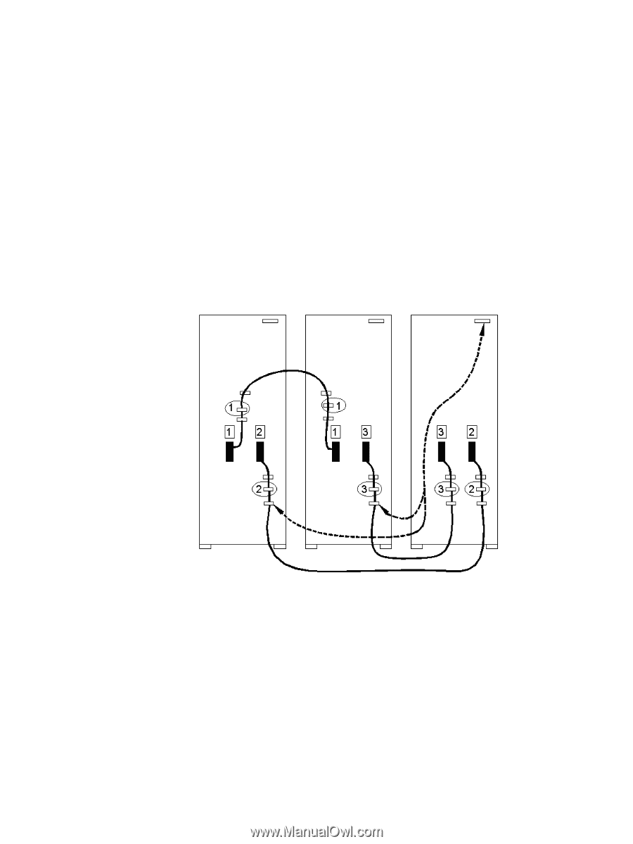
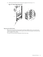
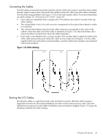
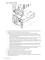
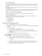
Connecting the Cables The I/O cables are attached and tied inside the cabinet. When the system is installed, these cables must be untied, routed, and connected to the cabinets where the other end of the cables terminate. Use the following guidelines and Figure 1-34 to route and connect cables. For more information on cable routing, see "Routing the I/O Cables" (page 45). • Each cabinet is identified with a unique color. The cabinet color label is located at the top of the cabinet. • The colored label closest to the cable connector corresponds to the color of the cabinet to which it is attached. • The colored label farther away from the cable connector corresponds to the color of the cabinet where the other end of the cable is attached. In Figure 1-34, the dotted lines show where the label is located and where the cable terminates. • Each cable is also labeled with a unique number. This number label is applied on both ends of the cable and near the port where the cable is to be connected. In Figure 1-34, the cable number labels are indicated by circled numbers, and the cabinet port numbers are indicated with boxed numbers. Figure 1-34 Cable Labeling Routing the I/O Cables Routing the cables is a significant task in the installation process. Efficient cable routing is important not only for the initial installation, but also to aid in future service calls. The most efficient use of space is to route cables so that they are not crossed or tangled. Figure 1-35 (page 46) illustrates efficient I/O cable routing. Setting Up the System 45
-
 1
1 -
2
-
3
-
4
-
5
-
6
-
7
-
8
-
9
-
10
-
11
-
12
-
13
-
14
-
15
-
16
-
17
-
18
-
19
-
20
-
21
-
22
-
23
-
24
-
25
-
26
-
27
-
28
-
29
-
30
-
31
-
32
-
33
-
34
-
35
-
36
-
37
-
38
-
39
-
 40
40 -
 41
41 -
 42
42 -
 43
43 -
 44
44 -
 45
45 -
 46
46 -
 47
47 -
 48
48 -
 49
49 -
 50
50 -
51
-
52
-
53
-
54
-
55
-
56
-
57
-
58
-
59
-
60
-
61
-
62
-
63
-
64
-
65
-
66
-
67
-
68
 |
 |