HP Superdome SX2000 Installation Guide, Sixth Edition - HP Integrity Superdome - Page 46
Routing I/O Cables, cage and work toward the left.
 |
View all HP Superdome SX2000 manuals
Add to My Manuals
Save this manual to your list of manuals |
Page 46 highlights
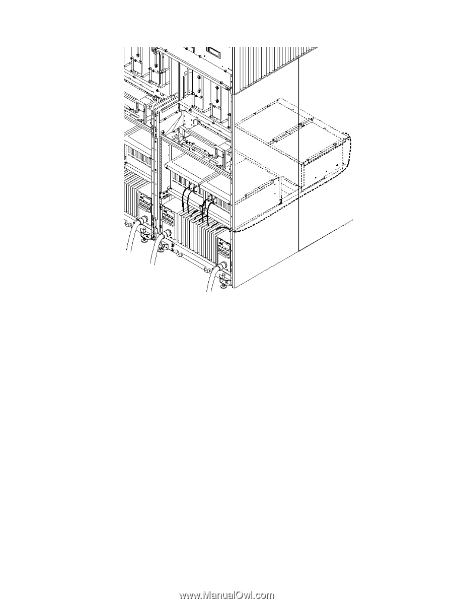
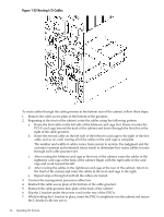
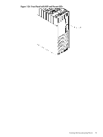
Figure 1-35 Routing I/O Cables To route cables through the cable groomer at the bottom rear of the cabinet, follow these steps: 1. Remove the cable access plate at the bottom of the groomer. 2. Beginning at the front of the cabinet, route the cables using the following pattern: a. Route the first cable on the left side of the leftmost card cage first. Route it under the PCI-X card cage toward the back of the cabinet and down through the first slot at the right of the cable groomer. b. Route the second cable on the left side of the leftmost card cage to the right of the first cable, and so on, until routing all of the cables in the card cage is complete. The number and width of cables varies from system to system. Use judgment and the customer's present and estimated future needs to determine how many cables to route through each cable groomer slot. c. After routing the leftmost card cage at the front of the cabinet, route the cables in the rightmost card cage at the back of the cabinet. Begin with the right cable in the card cage and work toward the left. d. After routing the cables in the rightmost card cage at the rear of the cabinet, return to the front of the system and route the cables in the next card cage to the right. e. Repeat steps a through d until all the cables are routed. 3. Connect the management processor cables last. 4. Reattach the cable access plate at the bottom of the cable groomer. 5. Reattach the cable groomer kick plate at the back of the cabinet. 6. Slip the L bracket under the power cord on the rear of the PDCA. 7. While holding the L bracket in place, insert the PDCA completely into the cabinet and secure the L bracket with one screw. 46 Installing the System
-
 1
1 -
2
-
3
-
4
-
5
-
6
-
7
-
8
-
9
-
10
-
11
-
12
-
13
-
14
-
15
-
16
-
17
-
18
-
19
-
20
-
21
-
22
-
23
-
24
-
25
-
26
-
27
-
28
-
29
-
30
-
31
-
32
-
33
-
34
-
35
-
36
-
37
-
38
-
39
-
40
-
 41
41 -
 42
42 -
 43
43 -
 44
44 -
 45
45 -
 46
46 -
 47
47 -
 48
48 -
 49
49 -
 50
50 -
 51
51 -
52
-
53
-
54
-
55
-
56
-
57
-
58
-
59
-
60
-
61
-
62
-
63
-
64
-
65
-
66
-
67
-
68
 |
 |